![]() Elixo 500 3S RTS 24V Comfort Pack
Elixo 500 3S RTS 24V Comfort Pack
Instruction Manual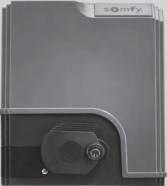 ELIXO 500 3S io
GENERAL INFORMATION
This product, installed in accordance with this guide, complies with standards EN 12453 and EN 13241-1.
The instructions referred to in the product’s installation guide and instructions for use are designed to prevent damage to property and personal injury along with compliance with the above standards.
Somfy declares that this product complies with the essential requirements and other relevant provisions of Directive 1999/5/EC. A Declaration of Conformity is available at www.somfy.com/ce (ELIXO 500 3S io).
Product can be used in the European Union, Switzerland and Norway.
SAFETY INSTRUCTION
Caution
Always read this installation guide and the attached safety instructions before installing this Somfy product.
This guide describes how to install, commission and operate this product. Follow all the instructions as incorrect installation can lead to serious injury.
Any use outside the sphere of application specified by Somfy is forbidden. This invalidates the warranty and discharges Somfy of all liability, as does any failure to comply with the instructions given herein.
This Somfy product must be installed by a professional motorisation and home automation installer, for whom this guide is intended.
Moreover, the installer must comply with current standards and legislation in the country in which the product is being installed, and inform his customers of the conditions for use and maintenance for the product. It is the installer’s responsibility to ensure that the automatic installation and its operation are compliant with the standards in force.
This device is not designed to be used by persons (including children) whose physical, sensory or mental capacity is impaired, or persons with little experience or knowledge, unless they are under supervision or have received instructions on using the device by a person responsible for their safety.
Safety instructions relating to installation ![]() Somfy refuses to accept any responsibility as regards the safety and correct operation of the motorisation if non-Somfy components are used.
Somfy refuses to accept any responsibility as regards the safety and correct operation of the motorisation if non-Somfy components are used.
No modifications may be made to the components of the motorisation system unless expressly authorised by Somfy.
Inform the user about the operation of the control systems and the manual opening procedure in the event of an emergency.
Installations which do not comply with the specifications in this manual or improper use of the product may cause injury or damage the equipment.
Installation area
- Before installation, ensure that the installation location complies with the provisions of the current standards. In particular, the position in which the motorisation mechanism will be fitted must allow for safe and easy manual release of the gate.
- Ensure that there are no danger zones (risk of crushing, cutting, trapping) between the gate and the surrounding fixed elements caused by the opening movement of the gate.
- Do not install the product in an explosive environment.
- Maintain a clear area of 500 mm behind the gate when it is completely open.
Installation
- Before installation, ensure that the gate frame conforms to current standards, particularly:
- The gate sliding rail must be straight and horizontal and the wheels must be able to support the weight of the gate.
- The gate should be able to be moved easily, manually, over its entire travel and there should be no sign of excessive side sway.
- The upper guide should allow the gate exact clearance to ensure regular, silent movement.
- End stops must be installed on the ground at both the opening and closing ends.
- On a barred gate, if the bars are more than 40 mm apart, install an appropriate safety device to prevent cutting.
- Watch the gate while it is moving.
- Manual unlocking may result in uncontrolled movement of the gate leaf.
- Place the fixed control devices and remote controls out of the reach of children.
- Any switch without a locking device must be installed in direct view of the gate and away from any mobile parts. The minimum height at which it must be installed is 1.5 m. It must not be accessible to the public.
During installation of the motorisation
- Remove any jewellery (bracelets, chains, etc.).
- For drilling and welding operations, wear special glasses and sufficient protection.
- Use the appropriate tools.
- Do not connect to the mains or to a backup battery before installation is complete.
- Be careful when handling the motorisation system to prevent any risk of injury.
Power supply
- In order to operate, the motor must be supplied with 230 V 50 Hz. The electric line should:
- solely be used for the motor,
- have a minimum cross section of 1.5 mm²,
- be fitted with an approved all-pole switch with contact openings of at least 3.5 mm, fitted with a protection device (fuse or circuit breaker with a 16 A rating) and a differential device (30 mA),
- be installed in accordance with the current electrical safety standards,
- be fitted with a lightning conductor (in compliance with standard NF C 61740, maximum residual voltage 2 kV),
- Check whether the earthing system is performed correctly: connect all the metal parts of the assembly and all the components of the installation equipped with earth terminals.
- After installation, ensure that the mechanism is correctly adjusted and that the protection system and any manual release mechanism operate correctly.
Safety devices
- The selected safety accessories for the installation must comply with the current standards and regulations in force in the country in which the product is being installed. The use of any safety components not approved by Somfy remains the sole responsibility of the installer.
- Install all the safety devices (photoelectric cells, safety edges, etc.) required to protect the zone from the danger of crushing, movement force and cutting according to the applicable directives and technical standards.
- In accordance with standard EN 12453 governing the safe use of motorised gates and doors, the use of the TAHOMA control box to automatically control a garage door or gate not visible to the user requires the installation of a photoelectric cell type safety device with autotest on the automatic control system.
Maintenance
- Regularly check the condition of the gate. Gates in poor condition must be repaired, reinforced or even replaced. Check that the various motorisation component’s screws and fittings are correctly tightened.
- Before carrying out work on the installation, switch off the power supply.
- Use only original parts for any maintenance or repair work.
Motorising an existing gate
Carry out a stress test with a measuring device which conforms to the requirements set out on in clause 5.1.1 of standard EN 12445.
PRODUCT DESCRIPTION
Area of application
Sliding gates up to 500 kg and carrying out 30 manoeuvres per day.
To ensure the safety of all equipment and persons, respect the information given in the table:
| For a gate weighing … | use … | Ref. |
| 0 to 300 kg | a passive rubber block on the end of the gate | 9014597 |
| 300 to 500 kg | a passive rubber block on the end of the gate | 9014598 |
If using a different rubber block to those listed above, ensure that the installation conforms with current regulations.
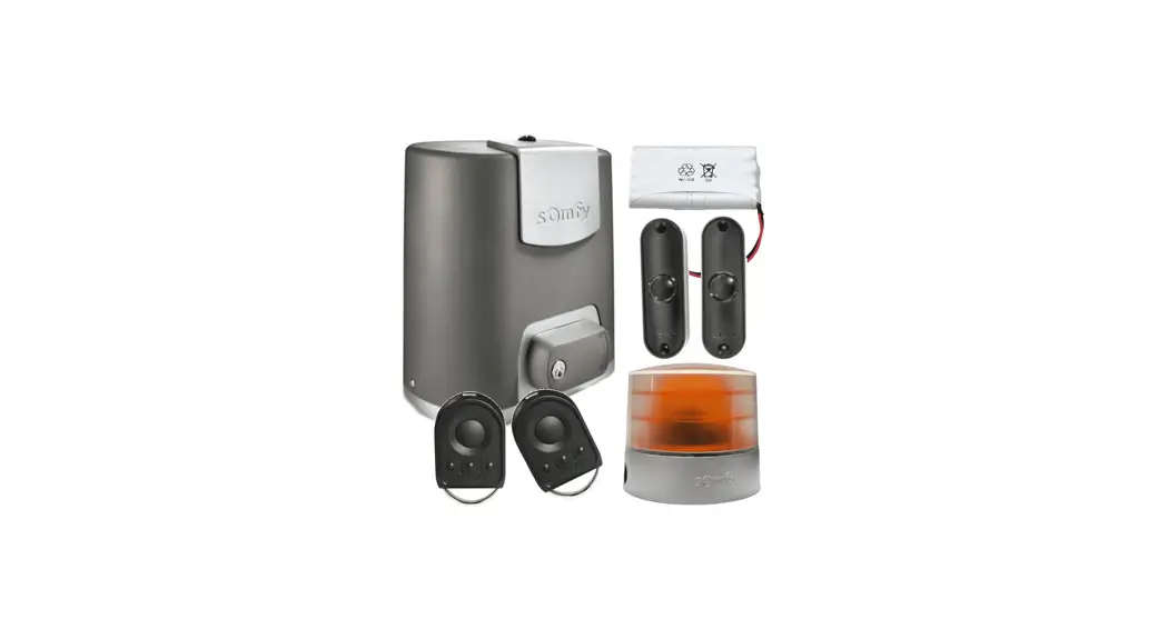
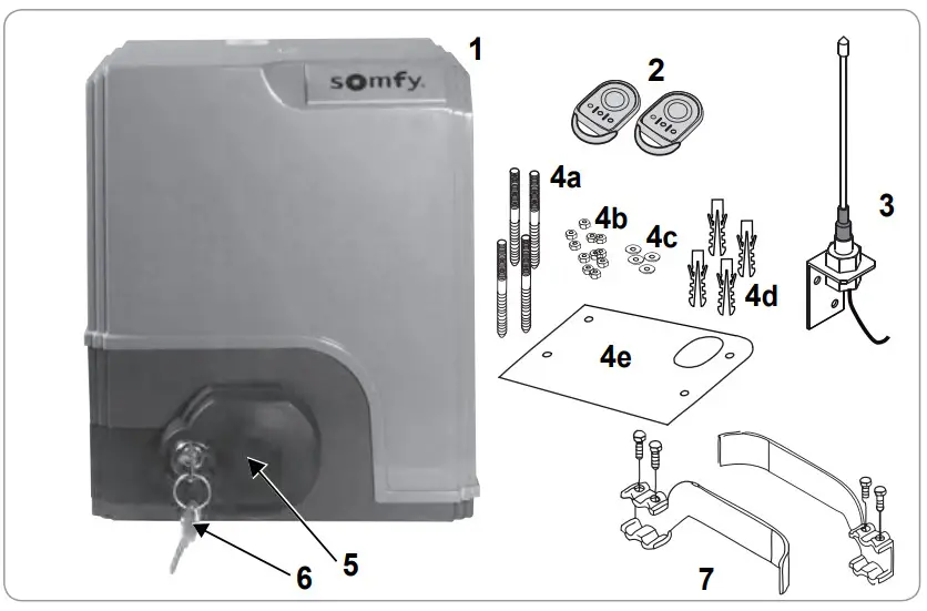
Contents of the standard kit
| 1 | Elixo 24 V Motor | x 1 |
| 2 | KEYGO io remote control | x 2 |
| 3 | Offset io aerial | x 1 |
| Ground mounting kit: | ||
| 4a | Lag screws | x 4 |
| 4b | Nut | x 8 |
| 4c | Washer | x 4 |
| 4d | Plug | x 4 |
| 4e | Base plate | x 1 |
| 5 | Manual release handle assembly | x 1 |
| 6 | Handle locking key | x 2 |
| 7 | End limit brackets | x 2 |
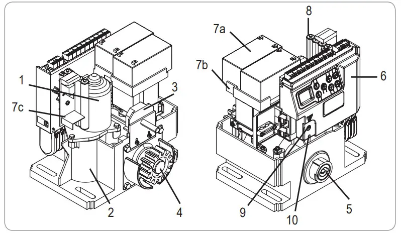
Description of the motorisation
| 1 | Motor |
| 2 | Reduction unit with worm screws – helicoid drive wheel |
| 3 | Electromechanical end limit unit |
| 4 | Pinion |
| 5 | Manual release mechanism |
| 6 | Control unit |
| Battery pack (optional, ref. 9014612): | |
| 7a 7b | 2 backup batteries |
| 7c 8 | Battery holder tray |
| 9 | Battery power supply management card |
| 10 | Battery pack (option, ref. 9001001) |
| Fuse (250 V/5 A) for 230 V lighting output | |
| Spare fuse (250 V/5 A) | |
Description of the interface
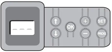
3-digit lCd screen
Display of parameters, codes (operation, programming, faults and breakdowns) and memorised data.
Para meter value display:
- fixed = value selected/auto-adjusted
- flashing = value selectable for parameter
| Button | Function |
| – navigate the parameters and codes list: • short press = scroll through individual parameters • press and hold = scroll rapidly through parameters | |
| – start auto-programming cycle – confirm parameter selection – confirm parameter value | |
| – modify a parameter value • short press = scroll through individual parameters • press and hold = scroll rapidly through parameters – use of forced operating mode by pressing and holding | |
| – Press 0.5 s: access and exit the parameter setting menu – Press 2 s: trigger auto-programming – Press 7 s: clear auto-programming and parameters – interrupt auto-programming | |
| – Press 2 s: memorise the remote controls – Press 7 s: Clearing the remote controls |
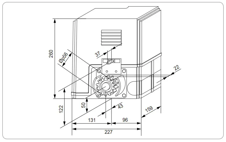
General motor size
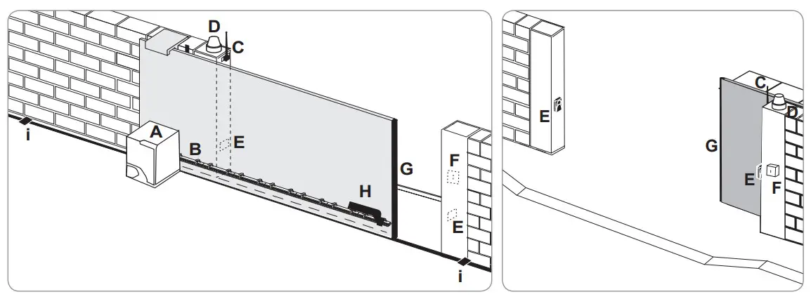
General view of a standard installation
| A | Motor |
| B | Rack |
| C | Aerial |
| D | Orange light |
| E | Set of photoelectric cells |
| F | Key lock |
| G | Passive rubber block |
| H | End limit brackets |
| I | End stops in the ground |
INSTALLATION
![]() The motorisation must be disengaged during installation.
The motorisation must be disengaged during installation.
assembling the manual release handle
[1]. Insert the release handle into the specific housing on the motor.
[2]. Tighten the release handle.
[3]. Fit the screw cover.
Unlocking the motor
[1]. Turn the key a quarter of a turn to the left.
[2]. Turn the release handle to the right.
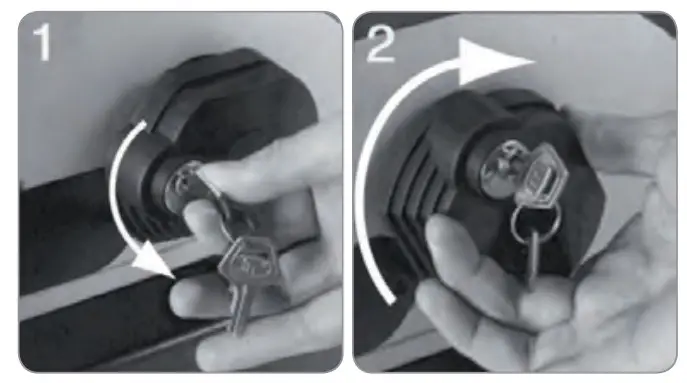
![]() Do not forcibly push the gate. Hold the gate over its entire travel during manual manoeuvres.
Do not forcibly push the gate. Hold the gate over its entire travel during manual manoeuvres.
installing the motorisation
Fitting the mounting system
The motor mounting kit provided is to be used on a concrete base. For all other types of mounting, use the appropriate fittings.
[1]. Position the base plate:
- parallel to the gate,
- with the symbol on the pinion pointing towards the gate,
- by moving it by 25 mm in relation to the front line of the rack (if the rack is fitted with a cover, measure from the line on the rack, not on the cover),
- so that it does not obstruct movement and to ensure the gate is able to open and close completely.
[2]. Mark the location for the ground mountings.
[3]. Drill to a depth of 85 mm.
[4]. Insert the plugs.
[5]. Tighten the lag screws on: - the threaded section for a rack height of between 110 and 130 mm,
- the threaded section + the unthreaded section for a rack height of between 100 and 110 mm.
To facilitate tightening of the lag screws, use 2 nuts to form a “double nut”.
[6]. Screw a nut onto each lag screw.
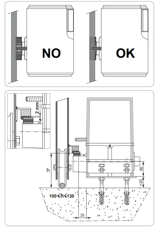
[7]. Place the base plate onto the lag screws with the symbol on the pinion pointing towards the gate. It must be a minimum of 23 mm from the ground. 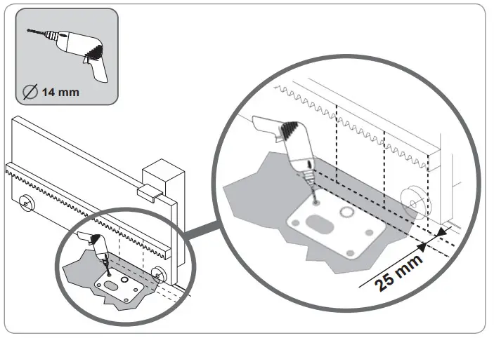
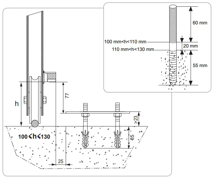
Mounting the motor
- Position the motor on the lag screws, insert it and push it towards the gate.
- Ensure the pinion is correctly positioned under the rack.
- Set the height of the motor and/or the rack to ensure a clearance of approximately 2 mm between the rack and the pinion. This setting is important to prevent premature wear of the pinion and rack; the pinion must not be supporting the weight of the gate.
- Check:
• that the setting nuts all come into contact with the base of the motor,
• the motor is level,
• the gate runs correctly,
• the clearance between the rack and pinion does not vary significantly over the gate’s travel. - Fit a washer and nut onto each lag screw in order to fit the motor.

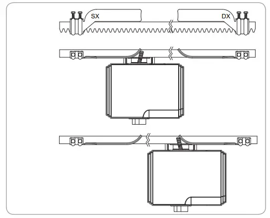
Fitting the end limit brackets
- Manually move the gate to the open position.
- Position a bracket onto the rack so that it activates the motor end limit contact.
- Screw the bracket onto the rack.
- Manually move the gate to the closed position then repeat steps 2 and 3 to fit the second bracket to the rack.
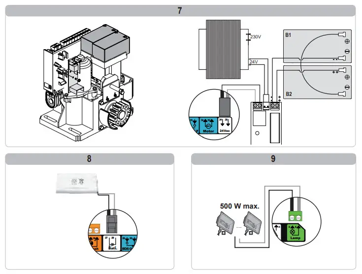
Connection to the power supply
Connect the live (L) to terminal 1 on the motor.
Connect the neutral (N) to terminal 2 of the motor.
Connect the earth wire to the earth terminal on the base of the motor.
switch on the power to the installation before commissioning.
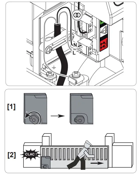
![]() The transformer is prewired (terminals 3 and 4). Do not alter the connections.
The transformer is prewired (terminals 3 and 4). Do not alter the connections.
Before quick commissioning
- Ensure the rail is clean.
- Manually move the gate to the intermediate position.
Re-engage the motorisation
- Turn the release handle to the left.
- Move the gate manually until the drive mechanism re-locks.
- Turn the key a quarter of a turn to the right.
QUICk COMMISSIONING
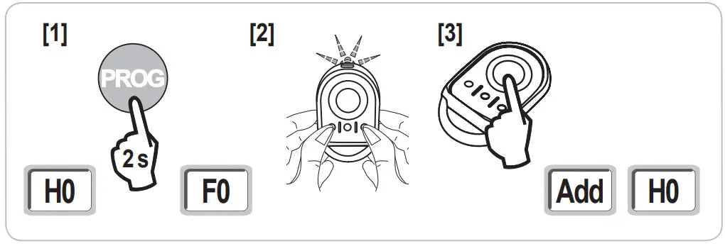
Memorising the keygo io remote controls for operation in complete opening mode
If this procedure is carried out using a channel which has already been memorised, this channel will be cleared.
- Press and hold the “ProG” button (2 s) on the programming interface. The screen displays “F0”.
- Press the outer left and right buttons on the remote control together. The remote control indicator light flashes.
- Press the button of the remote control that will open the gate fully. The screen displays “Add”.

Auto-programming
Auto-programming allows the gate’s speed, maximum torque and slowdown zones to be adjusted.
![]()
- Auto programming the gate’s travel is essential when commissioning the motor.
- The gate must be in the intermediate position before auto-programming starts.
- During auto-programming, the obstacle detection function is not active. Remove any objects or obstacles and do not allow any persons near or inside the operating range of the motorisation.
Start auto-programming
- Press and hold the “sEt” button (2 s). Release the button when the screen displays “h1”.
- Press “ok” to start auto-programming.
Auto-programming must start with the gate being opened.
The gate performs two complete Opening and Closing cycles.
To carry out an emergency stop during self-learning, use a stored remote control.
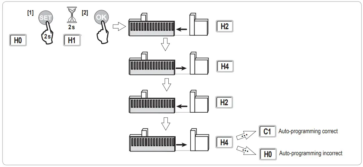
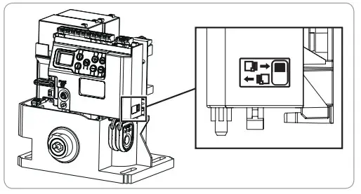
- If auto-programming starts with the gate being closed, stop auto-programming, push the slide as shown opposite then restart auto-programming.
- If auto-programming is correct, the display indicates “C1”.

- If auto-programming has not completed correctly, the display indicates “h0”.
Auto-programming can be interrupted by:
- activating a safety input (photoelectric cells, etc.)
- the appearance of a technical fault (thermal protection, etc.)
- pressing a control button (motor electronics, memorised remote control, wired control point, etc.).
In case of interruption, the display indicates “h0” and the motor returns to “awaiting setting” mode.
During auto-programming, if the gate is stationary, pressing “sEt” will exit auto-programming mode.
Note: It is possible to access auto-programming mode at any time including when the auto-programming cycle has already been completed and the display indicates “C1”.
OPERATING TEST
Complete opening operation
Obstacle detection operation
Obstacle detection when opening = stop + partial reversal.
Obstacle detection when closing = stop + complete reopening.
operation of the photoelectric cells
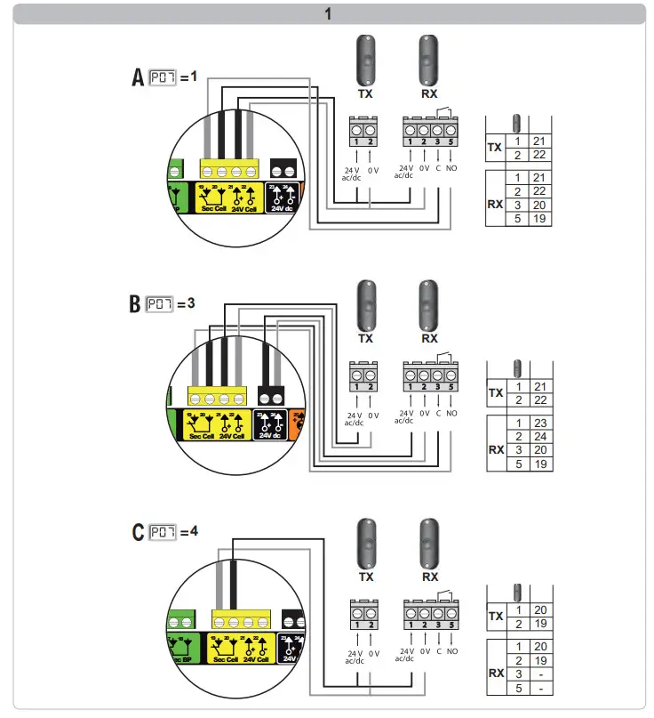
with the photoelectric cells connected to the dry/Cell contact (terminals 19-20) and Cell safety input parameter P07 = 1.
Cells obscured with gate closed/open = the gate cannot be moved until the operating mode changes to deadman operation (after 3 minutes).
Cells obscured when opening = the state of the cells is not taken into account and the gate continues to move.
Cells obscured when closing = stop + complete reopening.
safety edge operation (closing only)
Activation of the safety edge when closing = stop + complete reopening.
Specific operation
See the user booklet.
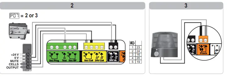
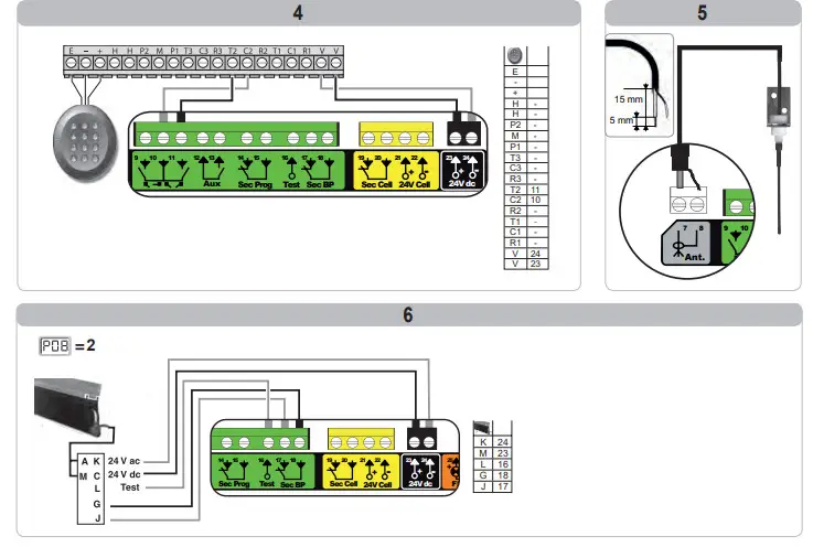
GENEral WIRING DIAGRAM
| terminals | terminal indications | Connection | Conirnank |
| 1 | L | 230 V power supply Note: Earth connection available on the motor body | |
| 2 | N | ||
| 3 | L | Transformer primary supply output | |
| 4 | N | ||
| 5 | N | 230 V lighting output | Max. power 500 W |
| 6 | L | Protected by 5A time-delay fuse | |
| 7 | Conductor | Aerial | |
| 8 | Braid | ||
| 9 | Contact | PEDESTFUANICLOSING control input | PEDESTRIAN/OPENING cyde programmable |
| 10 | Shared | ||
| 11 | Contact | COMPLETE/CLOSING control input | COMPLETE/CLOSING cyde programmable |
| 12 | Shared | Auxiliary contact output | 24 V, 12 A outage |
| 13 | Contact | Safety Extra Low Voltage (SELV) | |
| 14 | Contact | Safety input 3 – programmable | |
| 15 | Shared | ||
| 16 | Contact Safety test output | ||
| 17 | Contact Safety input 2 – safety edge | Only compatible with a dry contact safety edge | |
| 18 | Shared | ||
| 19 | Contact | Safety input 1 – Cells | BUS compatible (see parameter table) |
| 20 | Shared | Used to connect RX cell | |
| 21 | 24 V Safety device power supply | ||
| 22 | 0V | Permanent if autotest not selected, controlled If autotest selected | |
| 23 | 24 V | 24 V accessories power supply | 12 A max for all accessories on all outputs |
| 24 | 0V | ||
| 25 | 24V- 15W | 24 V -15 W orange light output | |
| 26 | 0V | ||
| 27 | 9 V – 24 V | 9 V or 24 V low voltage supply input | Compatible batteries 9.6V and 24V |
| 28 | 0 V | At 9 V, degraded operation | |
| At 24 V, normal operation | |||
| 29 | EOS 0 Motor end limit | ||
| 30 | Shared | ||
| 31 | EOS F | ||
| 32 | 1 Motor | ||
| 33 | 2 | ||
| 34 35 | 24VAC | Transformer | |
CONNECTING ADDITIONAL DEVICE
Description of the various additional devices
Photoelectric cells (fig. 1)
Three types of connection are possible:
a: without autotest: programme parameter “P07” = 1.
b: with autotest: programme parameter “P07” = 3.
Allows an automatic test to be carried out to check the operation of the photoelectric cells each time the gate moves.
If the operating test result is negative, the gate cannot be moved until the operating mode changes to deadman operation (after 3 minutes).
C: bus: programme parameter “P07” = 4. Auto-programming must be repeated after the cell BUS has been connected.
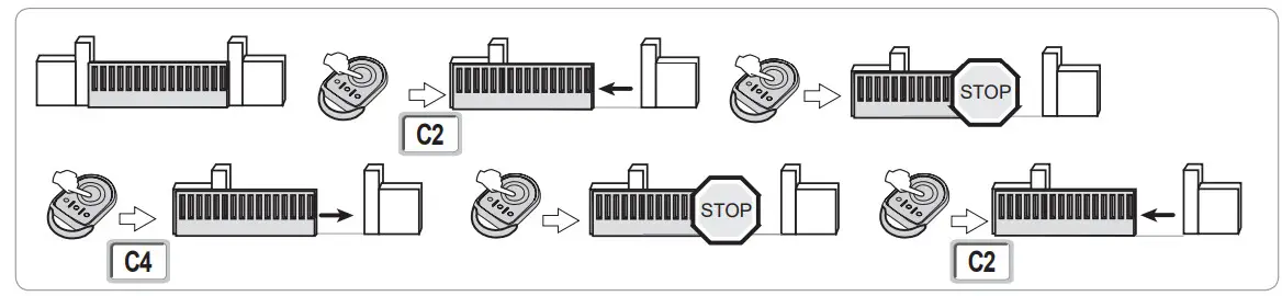
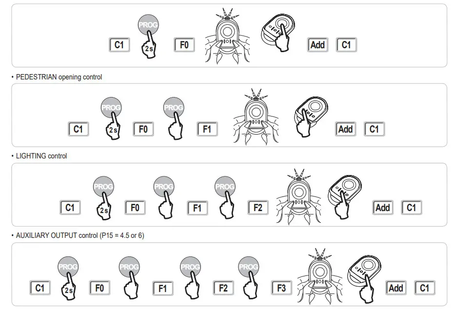
MEMORISING THE REMOTE CONTROL
General information
Remote control types
There are two types of remote control:
- monodirectional: Keygo io, Situo io, Smoove io
- bidirectional with information feedback function (remote controls indicate the movement in progress and issue confirmation of correct operation): Keytis io,Telis 1 io, Telis Composio io, Impresario Chronis io
Memorising the remote controls
There are two ways to memorise a remote control:
- memorising via the programming interface.
- memorising by copying a previously memorised remote control.
Each control button is memorised individually.
Memorising a button which has already been memorised will clear this button’s function.
Meaning of displayed codes
Memorising the keygo io remote controls memorising via the programming interface
- COMPLETE opening control
Memorising by copying a previously memorised keygo io remote control
This operation is used to copy the programming from a previously memorised remote control button.
- Press the outer left and right buttons on the previously memorised remote control together until the green indicator light flashes.
- Press and hold the button to be copied on the previously memorised remote control for 2 seconds.
- Briefly press the outer left and right buttons on the new remote control together.
- Briefly press the selected button to actuate the motorisation on the new remote control.
Argentina : Somfy Argentina
+55 11 (0) 4737-37000
United Kingdom : Somfy LTD
+44 (0) 113 391 3030
United States : Somfy Systems Inc
+1 (0) 609 395 1300