![]() INSTALLATION INSTRUCTIONS
INSTALLATION INSTRUCTIONS
Opti Guard™
Monitored Thru-Beam Photo Optic System![]() MODEL: OG-T-K10
MODEL: OG-T-K10
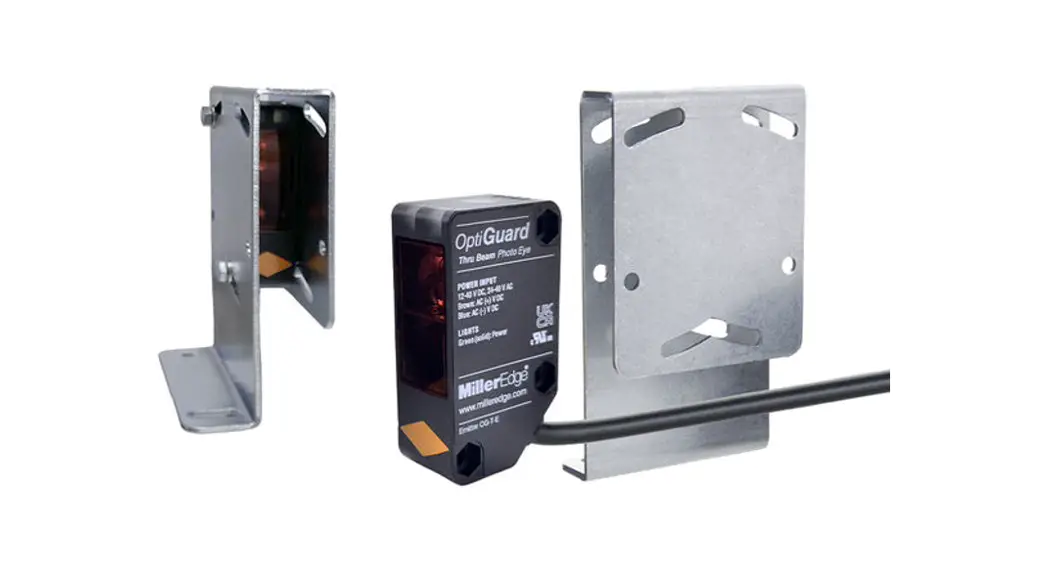
OG-T-K10 Opti Guard Monitored Thru-Beam Photo Optic System
WARNING
Read and understand all instructions before beginning installation. Disconnect power to motor and test upon completion.
Photo optics should be installed by qualified personnel to ensure the requirements herein have been met. Keep these instructions with the installation. Always abide by local and national electrical code specifications when wiring accessories to motor controls.
The Miller Edge Opti Guard monitored and fail-safe thru beam photo optic system is a UL Recognized Component that meets the UL 325 requirement. The Opti Guard consists of an emitter and a receiver with two mounting brackets. The emitter and receiver are intended to be positioned in such a way that an obstruction in a hazardous area will interrupt the beam of light. An interruption of the beam will signal the operator to stop and/or reverse motion.
CONTENTS
- (1) Emitter: OG-T-E
- (1) Receiver: OG-T-R
- (2) Bracket/hoods
- (4) Through-unit screws
- (4) Through-unit nuts
- (4) Through-unit washers
REQUIRED
- Mounting hardware as required by mounting surface
- Hand tools for hardware installation
RECOMMENDED
- Operator manual
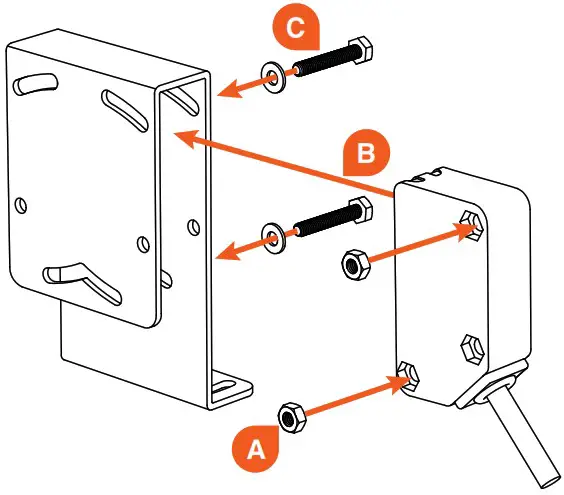 Image 1: Assembling the emitter or receiver into the bracket using the provided through-unit hardware
INSTALLATION
Select a stable mounting location with a clear line of site, across the protected area, to detect obstructions. The light beam should not be obstructed by plants, leaves, etc.
- Mount the emitter and receiver vertically or horizontally in their desired locations.
a) Install the emitter and receiver into their brackets. (Image 1)
i. Place provided nuts into the top and bottom recessed corners of the photo eyes. (A)
ii. Slide the photo eyes into their brackets. (B)
iii. Place washers onto screws and insert through bracket and emitter and receiver from the side opposite the nuts. Finger tighten to secure in place. (C)
b) Using the appropriate hardware required by the mounting surface, attach the mounting bracket. The emitter lens will point across the protected area toward the receiver mounting location. (Image 2) - Power the emitter and receiver. To avoid risk of electrocution, turn off and disconnect power to the operator before wiring.
a) Connect the emitter and receiver to the operator per the wiring diagram. (Figure 1)
b) Apply power to the operator.
c) Confirm the green LED lights on the emitter and receiver has turned on. (Figure 2) - Align the receiver with the emitter. (Image 2)
a) Aim the emitter toward the receiver. You can stand or kneel beside the unit, sighting along it and viewing the yellow receiver LED, to help with alignment. (Image 4)
b) With the hardware loosened, turn the emitter and receiver left and right and/or up and down until the yellow receiver LED turns on solid. (Image 3)
c) Tighten the mounting screws. Do not overtighten the through-unit screws.
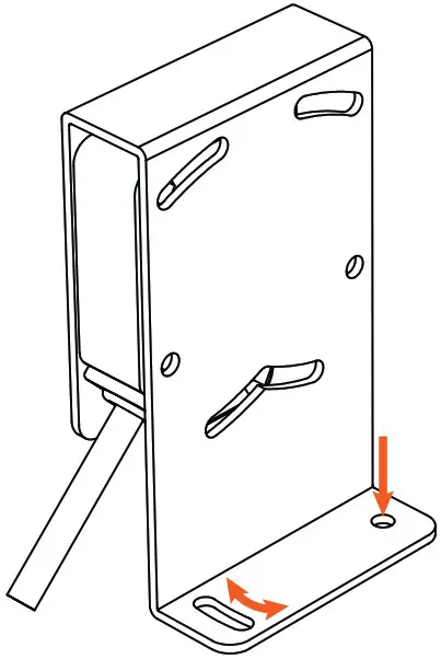 | 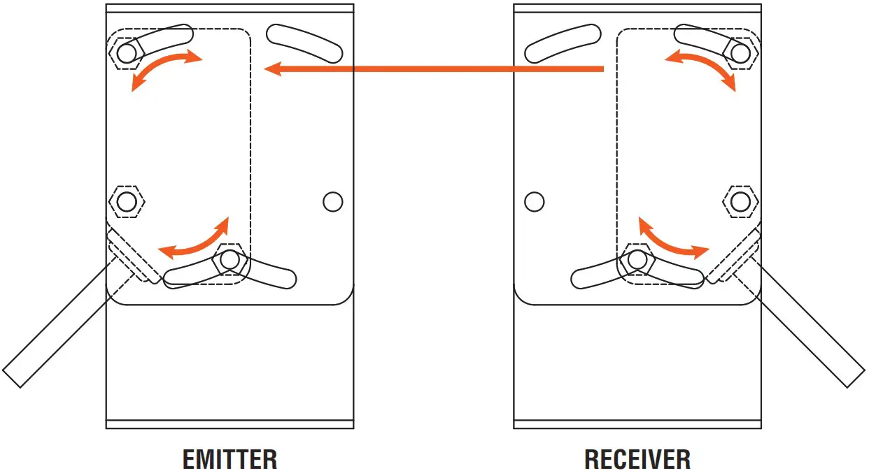 |
Image 2: Installing the emitter and receiver onto the mounting surface | Image 3: Aligning the emitter and receiver |
| NORMALLY CLOSED | 10K MONITORED | |
| WHITE | COM | COM |
| BLACK | Normally closed monitored input* | |
| GRAY | 10K monitored input | |
| BROWN | AC or (+)DC** | AC or (+)DC** |
| BLUE | AC or (-)DC** | . AC or (-)DC** |
| Outputs listed are with unit powered and aligned | ||
| * For N.C. monitoring, power may be a switched source ** Power source: 12-40 V DC, 24-48 V AC | ||
Figure 1: Wiring connection diagram
| GREEN | Solid: Power |
| YELLOW (receiver only) | Solid: Aligned Flashing: Signal is marginal |
Figure 2: LED indicators
TROUBLESHOOTING
| PROBLEM | REASON | SOLUTION |
| Green LED off | • No power | • Verify your power source • Refer to operator manual for switched power |
| Yellow LED off | • No signal • Emitter not seen | • Align emitter and receiver • Remove blockage |
| Yellow LED flashing | • Poor signal • Distance is too far | • Align emitter and receiver • Relocate components |
TECH SUPPORT
For additional assistance, contact Miller Edge Tech Support: 800-220-3343
GENERAL SPECIFICATIONS
PERFORMANCE
| Operating Range | 6-100 ft. (2-30 m) |
| Number of Elements | 1 element |
| Maximum Ambient Light | >100,000 lux |
| Aperture Angle | ±3° |
| Operating Temperature | -13°F to +131°F (-25°C to +55°C) |
| Agency Approvals | UL 325 Recognized Component |
ELECTRICAL
| Power Source | 12-40 volts DC, 24-48 volts AC |
| Current Consumption | <40 mA |
| Relay Rating | Maximum 40 volts AC/DC, 2 amp. |
| Output | N.C., 10K |
PHYSICAL
| Dimensions | Photo eye: 3/4 W x 2-1/2 H x 1-3/8 D in. (18 W x 62 H x 35 D mm) Bracket: 1-5/8 W x 4 H x 2-3/8 D in. (42 W x 113 H x 60 D mm) |
| Weight | Photo eye with cable: 5.5 oz. Bracket: 6.5 oz. |
| Housing Material | Photo eye: Polycarbonate housing, PMMA lens Bracket: Steel |
| LED Indicators | 2: Power, alignment |
| Cable Length | 6 ft., 20 AWG cable |
| Mounting Orientation | Vertical, horizontal |
| Degree of Protection | IP67 |
MAINTENANCE
It is strongly recommended that users check photo optics at least once per month for operation, and damage to housings and mountings. Also check for signs of damage to cables or connection points. Refer to your operator manual for detailed instructions about motor connections.
REPLACEMENT
To replace your Opti Guard, contact your sales representative. Attempting to repair your Miller Edge photo optic is nor commended and will void the manufacturer warranty.
WARRANTY
Opti Guard carries a 2-year warranty from date of shipment from Miller Edge for credit or replacement. This warranty applies to normal use, which is found to have defective materials or workmanship, as determined solely by an authorized factory representative. This warranty is void where evidence of misuse or abuse is present. This warranty covers repair or replacement of the purchased product only; product installation/labor charges are not covered. Miller Edge manufactures its products to meet stringent specifications and cannot assume responsibility for those consequences arising from improper installation or misuse. Installation instructions and testing procedures provided by Miller Edge must be followed for proper operation and maintenance.
ACCESSORIES
Contact your Miller Edge sales representative for photo optics accessories:
|
|
|
|
|
|
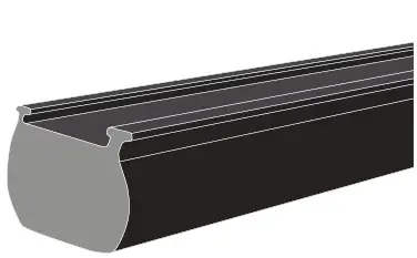 SENSING EDGES
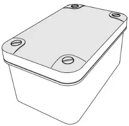 JUNCTION BOXES
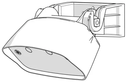 MOTION SENSORS
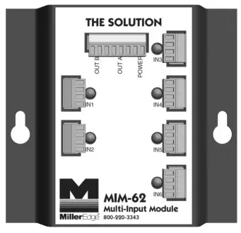 OPERATOR MODULES
 BUMPERS & SEALS
 WARNING LABELS
 www.milleredge.com
[email protected]
800-220-3343
OG-T_INST_20220225


