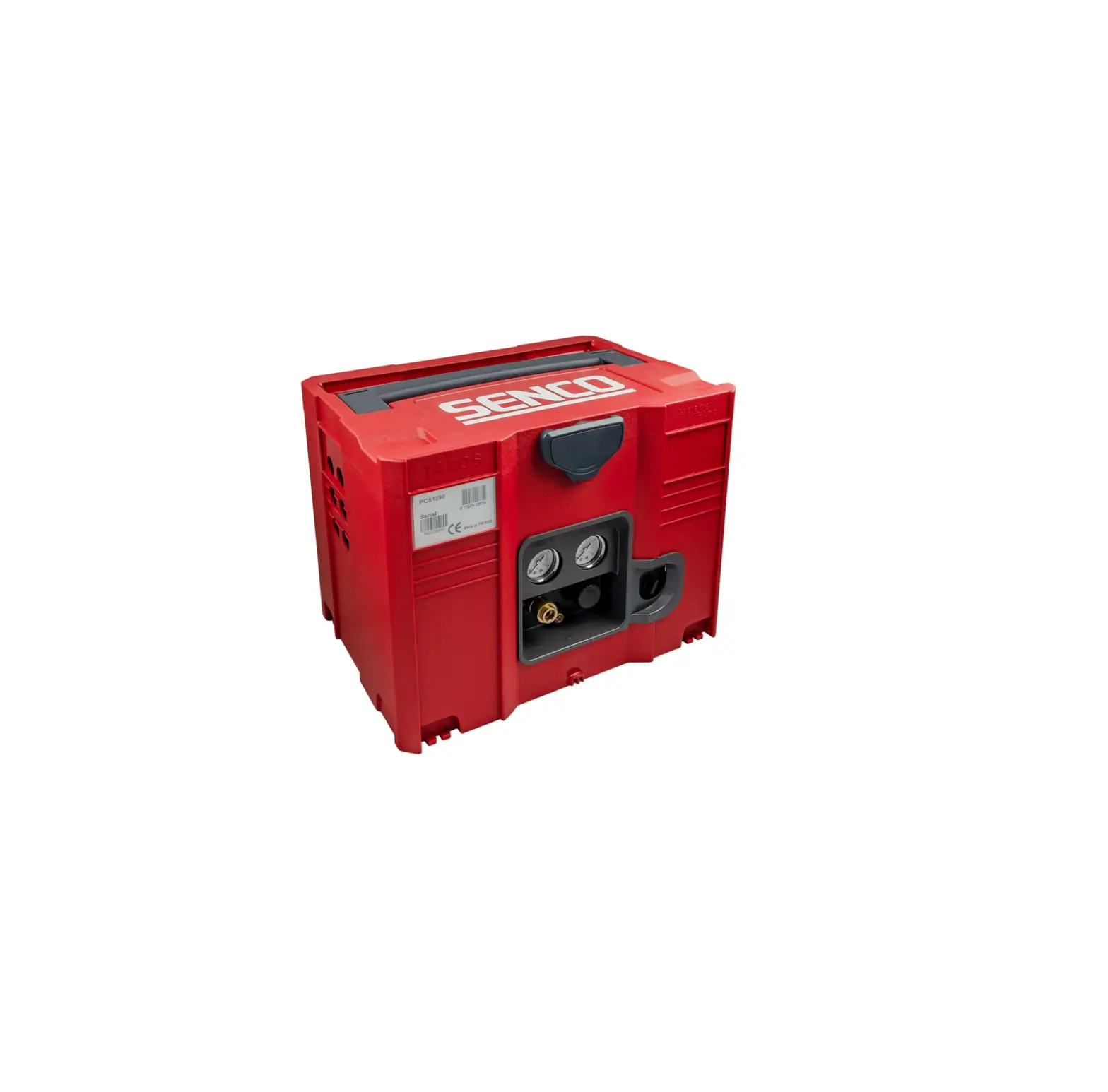
SENCO PCS1290 Electric Air Compressor
 Warnings for the safe use of this compressor are included in this manual.
 Read and understand this manual.
Introduction
Congratulations on the purchase of your new SENCO® Air Compressor! You can be assured your SENCO Air Compressor was constructed with the highest level of precision and accuracy. Each component has been rigorously tested by technicians to ensure the quality, endurance and performance of this air compressor.
This operator’s manual was compiled for your benefit. By reading and following the simple safety, installation and operation, and maintenance steps described in this manual, you will receive years of trouble free operation from your new SENCO Air Compressor. The contents of this manual are based on the latest product information available at the time of publication. The manufacturer reserves the right to make changes in price, color, materials equipment, specifications or models at any time without notice.
 Safety Alert!
A “DANGER, WARNING or CAUTION” safety warning will be surrounded by a “SAFETY ALERT BOX.” This box is used to designate and emphasize Safety Warnings that must be followed when operating this air compressor. Accompanying the safety warnings are “Signal Words” which designate the degree or level of hazard seriousness. The “Signal Words” used in this manual are as follows:
DANGER: Indicates an imminently hazardous situation which, if not avoided, WILL result in death or serious injury.
WARNING: Indicates an imminently hazardous situation which, if not avoided, COULD result in death or serious injury.
CAUTION: Indicates an imminently hazardous situation which, if not avoided MAY result in minor or moderate injury or damage to the air compressor.
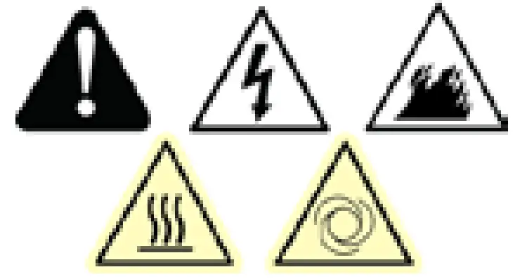 The symbols set to the left of this paragraph are “Safety Alert Symbols.” These symbols are used to call attention to items or procedures that could be dangerous to you or other persons using this equipment.
ALWAYS PROVIDE A COPY OF THIS MANUAL TO ANYONE USING THIS EQUIPMENT. READ ALL INSTRUCTIONS IN THIS MANUAL AND ANY INSTRUCTIONS SUPPLIED BY MANUFACTURERS OF SUPPORTING EQUIPMENT BEFORE OPERATING THIS AIR COMPRESSOR AND ESPECIALLY POINT OUT THE “SAFETY WARNINGS” TO PREVENT THE POSSIBILITY OF PERSONAL INJURY TO THE OPERATOR.
Inspection
Unbox the air compressor and write in the serial number in the space provided below. Inspect for signs of obvious or concealed freight damage. Be sure that all damaged parts are replaced and any mechanical problems are corrected prior to the operation of the air compressor.
If you have Questions or Comments call SENCO’s toll-free Action-line: 1-800-543-4596 or, e-mail: [email protected]
Please have the following information available for all service calls:
1. Model Number
2. Serial Number
3. Date and Place of Purchase
Senco, 4270 Ivy Pointe Blvd., Cincinnati, OH 45245
Safety Warnings
Read All Safety Warnings Before Using Air Compressor
Hazard | Potential Consequence | Prevention |
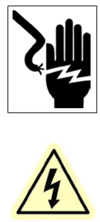
Risk of Electric Shock or Electrocution |
|
|
|
| |
|
| |
|
| |
Risk of Explosion or Fire |
|
|
|
| |
Risk of Bursting | · Serious injury or death may occur from an air tank explosion if air tanks are not properly maintained. | · Drain air tank daily or after each use to prevent moisture buildup in the air tank. · If air tank develops a leak, replace the air tank immediately. Never repair, weld or make modifications to the air tank or its attachments. · Never make adjustments to the factory set pressures. |
|
| |
Risk to Breathing |
|
|
|
| |
Risk of Burns |
|
|
Risk of Flying Objects |
|
|
Eye Protection Must Be Worn |
|
|
Risk from Moving Parts Warning: Unit May Start Without Warning |
|
|
|
| |
Risk from Negligence |
| |
Risk of Air Compressor Damage |
|
|


! SAVE THESE INSTRUCTIONS !
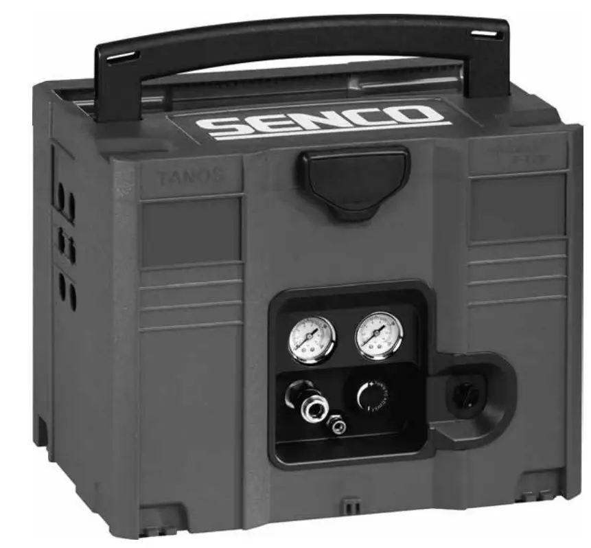
Compressor Features
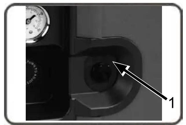
| 1 | Motor/Pressure Switch |
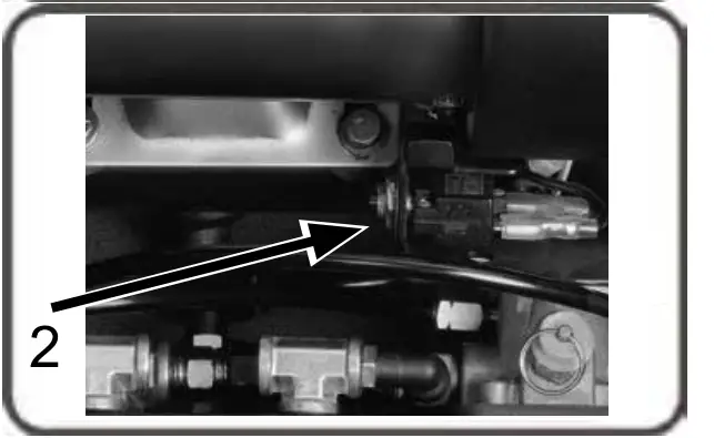
| 2 | Thermal Overload / Reset |
| 3 | Air Compressor Pump |
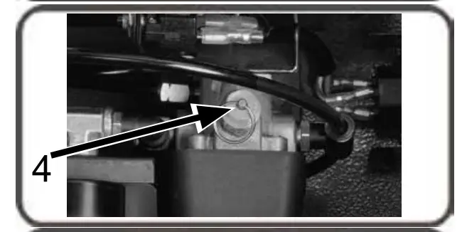
| 4 | Safety Relief Valve |
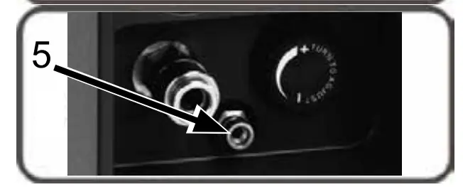
| 5 | Air Tank Drain Valve |
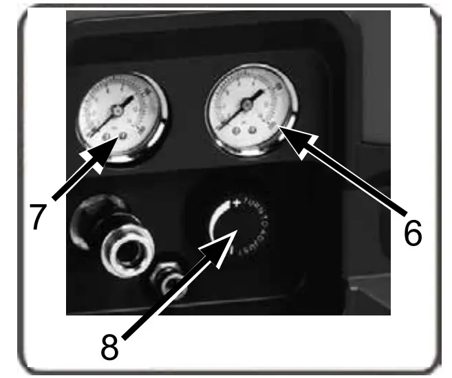
| 6 | Tank Pressure Gauge |
| 7 | Outlet Pressure Gauge |
| 8 | Pressure Regulator |
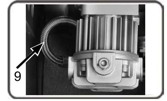
| 9 | Discharge Line |
| 10 | Quick Disconnect |
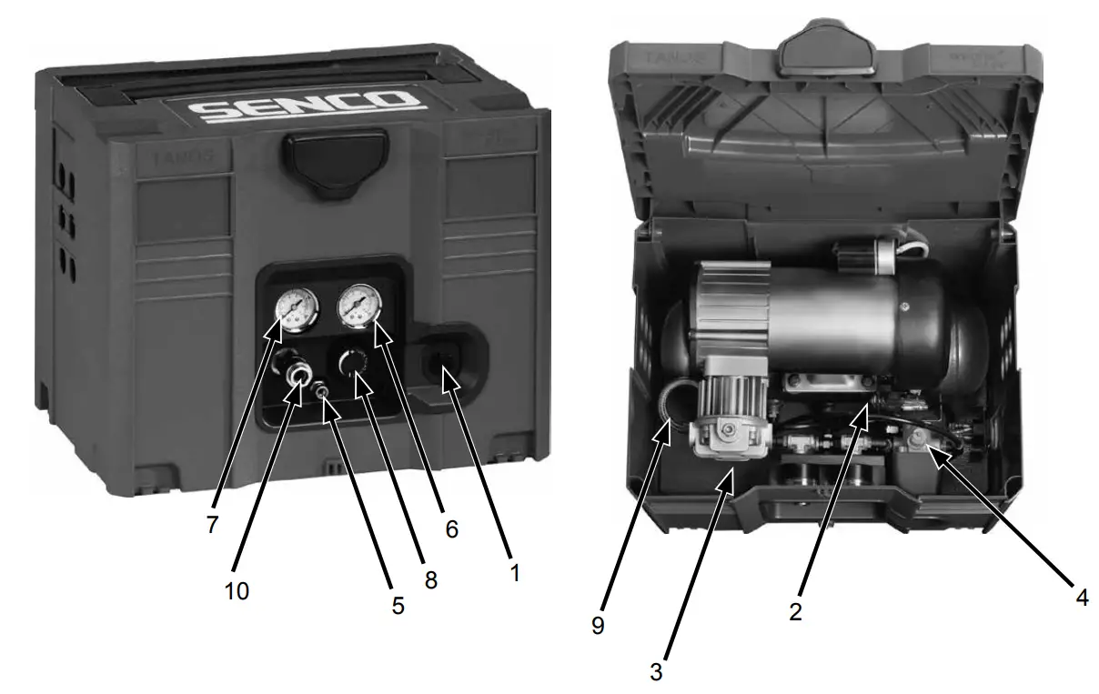
Compressor Features
- Motor/Pressure Switch: This switch is used to start or stop the air compressor. Moving the switch to the ON ( 1) position will provide automatic power to the pressure switch which will allow the motor to start when the air tank pressure is bellow the factory set cut-in pressure.
When in the ON ( 1) position, the pressure switch stops the motor when the air tank pressure reaches the factory set cut-out pressure. For safety purposes, this switch also has a pressure release valve located on the side of the switch designed to automatically release compressed air from the air compressor pump head and its discharge line when the air compressor reaches cut-out pressure or is shut off. This allows the motor to restart freely. Moving the switch to the OFF (0) position will remove power from the pressure switch and stop the air compressor.
- Motor Thermal Overload: Motor has a protective breaker located on the pump. Excessive amperage draw will result in the breaker tripping to protect the motor and operator. Reset the breaker by pushing the black plastic stem back into the housing. Reset switch if it is tripped.

- Air Compressor Pump: To compress air, the piston moves up and down in the cylinder. On the downstroke, air is drawn in through the air intake valve while the exhaust valve remains closed. On the upstroke, air is compressed, the intake valve closes and compressed air is forced out through the exhaust valve, into the discharge line, through the check valve and into the air tank.
- Safety Relief Valve: This valve is designed to prevent system failures by relieving pressure from the system when the compressed air reaches a predetermined level. The valve is preset by the manufacturer and must not be modified in any way. To verify the valve is working properly, pull on the ring. Air pressure should escape. When the ring is released, it will reseat.

- Air Tank Drain Valve: The drain valve is used to remove moisture from the air tank(s) after the air compressor is shut off. NEVER attempt to open the drain valve when more than 0.7 bar of air pressure is in the air tank! To open the drain valve, turn the knob counter-clockwise. Tilt tank to ensure that all condensation drains through valve.

- Air Tank Pressure Gauge: The air tank pressure gauge indicates the reserve air pressure in the air tank (s).
- Outlet Pressure Gauge: The outlet pressure gauge indicates the air pressure available at the outlet side of the regulator. This pressure is controlled by the regulator and is always less or equal to the air tank pressure.
- Pressure Regulator: The air pressure coming from the air tank is controlled by the regulator knob. Turn the pressure regulation knob clockwise to increase discharge pressure, and counter-clockwise to decrease discharge pressure. Follow tool operating instructions for recommended pressure range.

- Discharge Line: Please note that the discharge line is very hot. HOT SURFACES: Do not remove protective shroud. High temperature after sustained use.

Preparation
Initial Set-Up
Read safety warnings before setting-up air compressor
Location
Caution In order to avoid damaging the air compressor, do not incline the air compressor transversely or longitudinally more than 10º.
Place air compressor at least 30 cm away from obstacles that may prevent proper ventilation.
Do not place air compressor in an area:
- Where there is evidence of oil or gas leaks.
- Where flammable gas vapors or materials may be present.
 Warning
Serious injury or death may occur if electrical sparks from motor and pressure switch come in contact with flammable vapors, combustible dust, gases or other combustible materials. When using the air compressor for spray painting, place the air compressor as far away f rom the work area as possible, using extra air hoses instead of extension cords. - Where air temperatures fall below 0°C or exceed 40°C.
- Where extremely dirty air or water could be drawn into the air compressor.
 Warning
Electrical
 Danger
Improper connection of the equipment-grounding conductor can result in a risk of shock or electrocution. Check with a qualified electrician or service personnel if you are in doubt as to whether the outlet is properly grounded.
Do not use any type of adapter with this product. If repair or replacement of the cord or plug is necessary, do not connect the grounding wire to either flat blade terminal. The wire with insulation having an outer surface that is green with or without yellow stripes is the grounding wire.
Warning
This product must be grounded. If there should be a malfunction or breakdown, grounding provides a path of least resistance for electric current to reduce the risk of electric shock. This product is equipped with a cord having an equipment grounding conductor and a grounding type plug. The plug must be plugged into an appropriate outlet that is properly installed and grounded in accordance with all local codes and ordinances.
SENCO® DOES NOT RECOMMEND THE USE OF EXTENSION CORDS as this can create power loss and overheating of the motor. Use of an additional air hose is recommended rather than an extension cord. If use of an extension cord is unavoidable, it should be plugged into a GFCI found in circuit boxes or protected receptacles.
When using an extension cord, observe the following:
| Cable Length | Wire Gauge |
| Up to 8 meters | 12 AWG |
| Up to 30 meters | 10 AWG |
| Up to 50 meters | 8 AWG |
| Up to 75 meters | 6 AWG |
Use only extension cords having an electrical rating not less than the rating of the product. Do not use damaged extension cords. Examine extension cord before using and replace if damaged. Do not abuse extension cord and do not yank on any cord to disconnect. Keep cord away from heat and sharp edges. Always shut off the air compressor switch before removing the plug from the receptacle.
Operation
Pre-Start Checklist
- Remove any moisture in the air compressor tank. Remove excessive pressure by pulling on the safety relief valve ring or with an air tool, then open the air tank drain valve in the bottom of the air tank. Close tightly when drained.
 Warning: Risk of bodily injury. NEVER attempt to open the drain valve when more than 0.7 bar of air pressure is in the air tank!
 - Make sure the air compressor Motor Switch is in the OFF (0) position.
- Make sure all safety valves are working correctly.
- Make sure all guards and covers are in place and securely mounted.
Start-Up
- Ensure the lever on the pressure switch box is in the OFF (0) position.
- Plug the power cord into the grounded outlet.
- Move the motor switch to the ON (1) position.
- This will allow the air compressor to Start building up pressure in the air tanks and Stop when correct pressure is achieved. When pressure drops with usage, the air compressor will Start building up pressure again.
- Set pressure by adjusting the pressure regulator knob counter-clockwise for less pressure and clockwise for more pressure.
- If you notice any unusual noise or vibration, stop the air compressor and refer to “Troubleshooting.”
Shutdown
- To stop the air compressor, move the lever on the motor switch to the OFF (0) position. NEVER stop the air compressor by unplugging it from the power source. This could result in risk of electrocution.
- Drain air from the air tank by releasing air with an attached air tool or by pulling on the safety relief valve ring.
- Once pressure in the air tanks register under 0.7 bar, open the drain valve under each air tank to drain any moisture.
- Allow the air compressor to cool down.
- Wipe air compressor clean and store in a safe, non-freezing area.
Maintenance
Read the instruction manual before performing maintenance. The following procedures must be performed when stopping the air compressor for maintenance or service.
- Turn off the air compressor
 Warning: Never assume the air compressor is safe to work on just because it is not operating. It could restart at any time!
 - Disconnect cord from main power supply.
- Open all drains.
- Wait for the air compressor to cool before starting service.
Maintenance Chart
| Procedure | Daily | Weekly | Monthly |
| Drain condensation in air tank(s) | X | ||
| Check for unusual noise/vibration | X | ||
| Check for air leaks | X | ||
| Inspect air filter | X | ||
| Clean exterior of compressor | X | ||
| Check safety relief valve | X |
Troubleshooting
| Symptom 1. Motor will not run or restart. | |
| Probable Cause | Remedy |
|
|
|
|
|
|
|
|
|
|
“cut-in” pressure. |
|
|
|
|
|
| Symptom 2. When in the ON (1) position, motor runs continuously. | |
| Probable Cause | Remedy |
|
|
|
|
| Symptom 3. Air continues to leak at motor/pressure switch release valve after motor stops. | |
| Probable Cause | Remedy |
|
|
| Symptom 4. Air continues to leak at motor/pressure switch release valve after motor is running. | |
| Probable Cause | Remedy |
|
|
| Symptom 5. Air leaks from safety relief valve. | |
| Probable Cause | Remedy |
|
|
|
|
| Symptom 6. Air leaks at fittings. | |
| Probable Cause | Remedy |
|
Do not overtighten. |
| Symptom 7. Air leak in air tank. | |
| Probable Cause | Remedy |
|
Do not attempt to repair air tank! Do not weld, repair or make modifications. |
| Symptom 8. Air blowing from inlet filter. | |
| Probable Cause | Remedy |
|
|
| Symptom 9. Insufficient pressure at air tool or accessory. | |
| Probable Cause | Remedy |
|
|
|
|
|
|
|
|
| Symptom 10. Air compressor not making enough air. | |
| Probable Cause | Remedy |
|
|
|
|
| Symptom 11. Moisture in discharge air. | |
| Probable Cause | Remedy |
|
|
Compressor Specifications
| Model(s) | PCS1290 | |
| Motor | Horsepower peak (HP) | 1HP |
| Horsepower running (HP) | 0.72HP | |
| Power peak (kW) | 0.75KW | |
| Power running (kW) | 0.54KW | |
| Voltage (V) | 230V | |
| Frequency (Hz) | 50Hz | |
| RPM | 2850 | |
| Compressor pump | Number of cylinders | 1 |
| Compression stage | 1 | |
| Crankcase | Aluminum | |
| Bearings | Ball | |
| Cylinder | Aluminum | |
| Valves | Reed-Single | |
| Head | Aluminum | |
| Filter | Insert | |
| Motor/Pressure switch setting | Cut-out (bar) | 8,6 |
| Cut-in (bar) | 6,2 | |
| Controls | ON(1)/OFF(0) | |
| Air tank | Capacity (l) | 4 |
| Performance | Air displacement (l/min) | 90 |
| Maximum pressure (bar) | 8,6 | |
| l/min @ 4 bar | 54 | |
| l/min @ 6 bar | 46 | |
| l/min @ 7 bar | 38 | |
| l/min @ maximum pressure | 33 | |
| Pump-up time: 0-max bar (s) | 60 | |
| Recovery time: 7-max bar (s) | 10 | |
| Air outlet | Connector type | 3-in-1 universal |
| Number of air outlets | 1 | |
| Dimension air outlet (inch) | 1/4″ | |
| Weight | Net (kg) | 16,5 |
| Dimensions | Basic L x W x H (cm) | 40x30x32 |
| Noise | Measured sound power level (dBA) | 88 |
| Guaranteed sound power level (dBA) | 90 | |
Declaration of Conformity
We Senco Brands, BV.
of Geurdeland 17E
6673 DR Andelst, The Netherlands
in accordance with the following directive(s):
2006/42/EC,2014/30/EU, 2014/35/EU,2000/14/EC
2011/65/EU, 2005/88/EC, 2009/105/EC
declare under our sole responsibility that:
Model(s): PCS1290
is in conformity with the applicable essential health and safety requirements of the following documents:
BS EN 1012-1:2010, EN ISO 14121-1:2007,
EN 60204-1:2006+A1:2009, EN 286-1:1998
Signed by: Peter van der Wei
Position: Director
Place of DOC: Senco Brands, BV. Geurdeland 17E 6673 DR Andelst The Netherlands
Limited Warranty
Senco Professional End User Warranty Policy
Considering the following constraints Send underwrites the reliability and the quality of its supplied authorised Senco Pranced products
- Senco warrants to the end user that the following products will be tree from detects in construction, assembly and material for the warranty period specified below.
Product Warranty period Senco V XP Series-Red Cap pneumatic tools Five years Senco 0 XP Series-Back Cap, pneumatic tools Two years Senco Pro Series, pneumatic tools One year Senco Semi-Pro Series, pneumatic tools One year Senco DuraSpin 0 Series, electric and battery toots One year Senco Cordless battery tools Two years Senco batteries and chargers for tools One year Senco gas tools Two years Senco Reconciboned Products Ole ;ear Senco other tools One year Senco Compressors One year - The warranty period starts on the day the end user purchases the product and/or 1 year after the tool has been deleted from the product line, which ever date comes first
- To claim warranty the end user needs to send the detective products or their parts including the serial number and the original and dated sales receipt or proof of purchase from the original retailer or dealer, freight prepaid to the original retailer or dealer.
- Serco is not obliged to do any repairs or replacements on any products or their parts on site
- During the warranty period Senco or its distributors will repair or replace defective products or their parts, exclusively or mainly as a result of an imperfection in construction, assembly or material, at Sencos option and expense. subject to the constraints of this warranty policy
- The repair or replacement of products or their parts under warranty, does in no case lead to prolongation of the warranty period. For every replacement product or part. the remaining original warranty period of the replaced product or part is applicable
- Serco will become the owner of the products or parts that have been replaced by Senco or its distributors as a result of being compliant to Senco’s warranty, without being obligated any compensation in this matter.
- Excluded from the warranty are:
- Normal year and tear parts, for example rubber O-rings, seals, criver blades, piston stops. piston/driver assembles, isolators, drive bolts, air filters and fuel systems, bits;
- Any imperfection that is a result of or has evolved from the tact that there has not been used clean, dry regulated compressed at and/or the air pressure applied has exceeded the maximum indicated or the tool casting (pneumatic tools);
- Any imperfection that is a result of or has evolved from normal wear, misapplication, abuse/misuse improper modification or storage, shipping/transport accidents, neglect, operation at other than recommended speeds or voltage (electric units only);
- Any Imperfection that is a result of or has evolved from explosions, fires and natural disasters like hurricanes, floods and earthquakes.
- Any imperfection that is a result of or has evolved from not following operating instructions, specifications and / or maintenance schedules Read the Operator Manual for use, specifications and maintenance instructions;
- Any imperfection that is caused by repairs, modifications to the product or attempts to do so by the end user or any third party,
- Labour charges or loss or damage resulting from improper operation, maintenance or repairs are not covered by this warranty
- Any warranty claims that have been received after the warranty period, as specified in this end user warranty, has expired.
- Additional costs like shipping/transpor, special packaging requirements and costs of travel and accommodation, are at the end users expense
- If a complaint is unfounded, all costs incurred thereby, including handling, inspection, shipping and administrative costs on the side of Senco or its distributors, will be charged to the end user.
- After expiration of the warranty period, all costs `or repair or replacement, including handing, inspecton, shipping and administrative costs will be charged to the end user
- Notwithstanding legal limitation periods, the limitation of all claims and appears against Senco and third parties involved by Serco for the implemertation of the agreement is one year
- If Senco fails to meet this agieetnert, it will rut discharge the end user from the otligations arising under this or any ober contract
- When the warranty terms can not be met, due to for example import or export prohibitions, strikes or other unforeseen circumstances, the warranty period will be extended accordingly
- Senco’s lability is limited to ‘he warranty Santo is not liable for damage caused by try functioning or non-functioning of the products as delivered, repaired or modified by Senco or its distributors, including but not limited to, production losses, profit losses, reduced working range, commercial Ices or consequential damages or indirect damages whatsoever
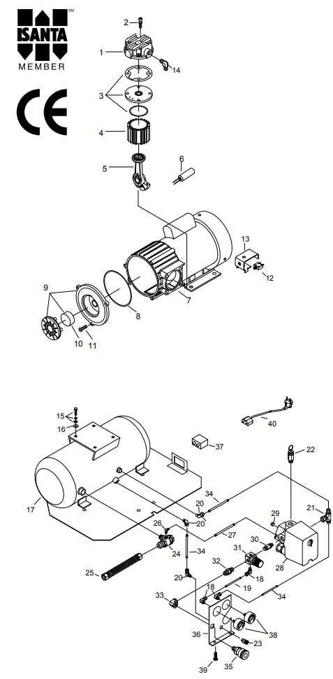
Parts
| Ref. No | Description | Part No. | Qty. |
| 1 | Cylinder head | 3101096NH | 1 |
| 2 | Allen bolt set | 3B01-M06*080V | 4 |
| 3 | Exhaust valve seat set | 3B11-A9000A | 1 |
| 4 | Cylinder | 3201065 | 1 |
| 5 | Rod set | 3B34-MB57B | 1 |
| 6 | Running capacitor | 2E27-010F4535 | 1 |
| 7 | Motor set | 3B8-MB5716RL | 1 |
| 8 | Front cover gasket | 2G07-009 | 1 |
| 9 | Air filter set | 2140022 | 1 |
| 10 | Filter element | 2142014 | 1 |
| 11 | Bolt | 2B02-FM5*015 | 3 |
| 12 | Circuit breaker | 2E25-03A | 1 |
| 13 | Bracket | 3427075 | 1 |
| 14 | Exhaust elbow | 2N06-02T03H | 1 |
| 15 | Hexagon bolt set | 3B00-FM06*015-RS | 1 |
| 16 | Body seat block | 2439008 | 1 |
| 17 | Air tank | 3401X077 | 1 |
| 18 | Pu hose connector | 07SPL6-01-A | 3 |
| 19 | Pu hose | 2T03-W02*0150 | 1 |
| 20 | Pu hose connector | 07SPL6-02-A | 3 |
| 21 | Pu hose connector | 07SPB6-02-A | 1 |
| 22 | Pressure relief valve | 2406018CE | 1 |
| 23 | Drain valve | 2405011 | 1 |
| 24 | Check valve | 2414036X | 1 |
| 25 | Exhaust soft tube | 2T02-03*0200RS | 1 |
| 26 | Elbow | 2N1 6-C01TW02M | 1 |
| 27 | Pu hose set | 3T03-W02*01 50D | 1 |
| 28 | Pressure switch | 2E21-070C | 1 |
| 29 | Plug | 2N33-009 | 1 |
| 30 | Nipple | 2N01-05 8RS | 1 |
| 31 | Regulator | 2408008RNX | 1 |
| 32 | Nipple | 2N01-045RS | 1 |
| 33 | Elbow | 2N07-02T02TC | 1 |
| 34 | Pu hose | 2T03-W02*0260 | 3 |
| 35 | Quick coupler | 07S1/4M-ERS | 1 |
| 36 | Panel | 3420112 | 1 |
| 37 | Socket | 2E05-SC-01 | 1 |
| 38 | Pressure gauge | 2D12-15D14BAR | 2 |
| 39 | Bolt | 2B02-FM5*010WB | 2 |
| 40 | Power cable | 2E01054 | 1 |
Customer Support
Verpa Senco BV
Pascallaan 88
8218NJ Lelystad
The Netherlands
EMEA: www.senco.eu