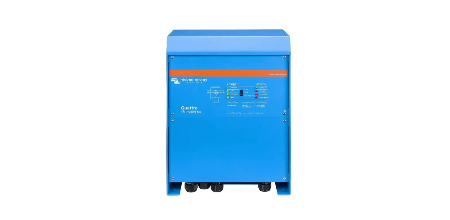

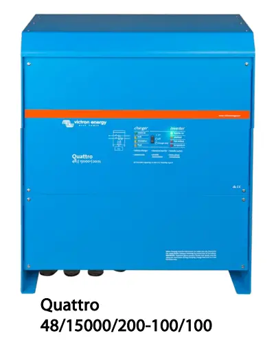
victron energy QUA485021100 Quattro Inverter Charger
INSTRUCTIONS
Two AC inputs with integrated transfer switch
The Quattro can be connected to two independent AC sources, for example the public grid and a generator, or two generators. The Quattro will automatically connect to the active source.
Two AC Outputs
The main output has no-break functionality. The Quattro takes over the supply to the connected loads in the event of a grid failure or when shore/generator power is disconnected. This happens so fast (less than 20 milliseconds) that computers and other electronic equipment will continue to operate without disruption.
The second output is live only when AC is available on one of the inputs of the Quattro. Loads that should not discharge the battery, like a water heater for example, can be connected to this output.
Split phase option
A split phase AC source can be obtained by connecting our autotransformer (see data sheet on www.victronenergy.com) to a ‘European’ inverter programmed to supply 240V / 60Hz.
Three phase capability
Three units can be configured for three phase output. But that’s not all: up to 4 sets of three 15kVA units can be parallel connected to provide 144kW / 180kVA inverter power and 2400A charging capacity.
PowerControl – Dealing with limited generator, shore side or grid power
The Quattro is a very powerful battery charger. It will therefore draw a lot of current from the generator or shore side supply (16A per 5kVA Quattro at 230VAC). A current limit can be set on each AC input. The Quattro will then take account of other AC loads and use whatever is spare for charging, thus preventing the generator or mains supply from being overloaded.
PowerAssist – Boosting shore or generator power
This feature takes the principle of PowerControl to a further dimension allowing the Quattro to supplement the capacity of the alternative source. Where peak power is so often required only for a limited period, the Quattro will make sure that insufficient mains or generator power is immediately compensated for by power from the battery. When the load reduces, the spare power is used to recharge the battery.
Solar energy: AC power available even during a grid failure
The Quattro can be used in off grid as well as grid connected PV and other alternative energy systems. Loss of mains detection software is available.
System configuring
- In case of a stand-alone application, if settings have to be changed, this can be done in a matter of minutes with a DIP switch setting procedure.
- Parallel and three phase applications can be configured with VE.Bus Quick Configure and VE.Bus System Configurator software.
- Off grid, grid interactive and self-consumption applications, involving grid-tie inverters and/or MPPT Solar Chargers can be configured with Assistants (dedicated software for specific applications).
On-site Monitoring and control
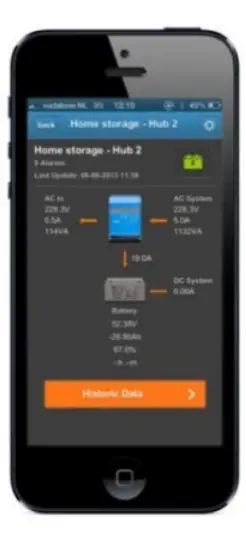
Several options are available: Battery Monitor, Multi Control Panel, Color Control GX or other GX devices, smartphone or tablet (Bluetooth Smart), laptop or computer (USB or RS232).
Remote Monitoring and control
Color Control GX or other GX devices. Data can be stored and displayed on our VRM (Victron Remote Management) website, free of charge.
Remote configuring
When connected to the Ethernet, systems with a Color Control GX or other GX device can be accessed and settings can be changed remotely.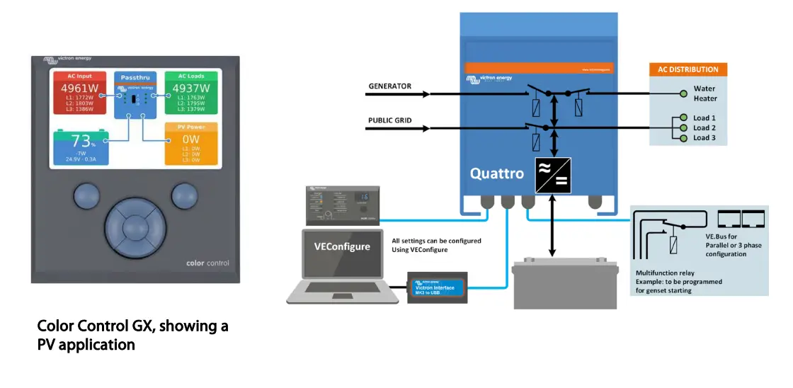
Models

Specifications
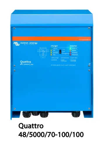
| Quattro | 12/3000/120-50/50 24/3000/70-50/50 | 12/5000/220-100/100 24/5000/120-100/100 48/5000/70-100/100 | 24/8000/200-100/100 48/8000/110-100/100 | 48/10000/140-100/100 | 48/15000/200-100/100 | |
| PowerControl / PowerAssist | Yes | |||||
| Integrated Transfer switch | Yes | |||||
| AC inputs (2x) | Input voltage range: 187-265 VAC Input frequency: 45 – 65 Hz Power factor: 1 | |||||
| Maximum feed through current (A) | 2x 50 | 2×100 | 2×100 | 2×100 | 2×100 | |
| INVERTER | ||||||
| Input voltage range (V DC) | 9,5 – 17V 19 – 33V 38 – 66V | |||||
| Output (1) | Output voltage: 230 VAC ± 2% Frequency: 50 Hz ± 0,1% | |||||
| Cont. output power at 25°C (VA) (3) | 3000 | 5000 | 8000 | 10000 | 15000 | |
| Cont. output power at 25°C (W) | 2400 | 4000 | 6400 | 8000 | 12000 | |
| Cont. output power at 40°C (W) | 2200 | 3700 | 5500 | 6500 | 10000 | |
| Cont. output power at 65°C (W) | 1700 | 3000 | 3600 | 4500 | 7000 | |
| Peak power (W) | 6000 | 10000 | 16000 | 20000 | 25000 | |
| Maximum efficiency (%) | 93 / 94 | 94 / 94 / 95 | 94 / 96 | 96 | 96 | |
| Zero load power (W) | 20 / 20 | 30 / 30 / 35 | 60 / 60 | 60 | 110 | |
| Zero load power in AES mode (W) | 15 / 15 | 20 / 25 / 30 | 40 / 40 | 40 | 75 | |
| Zero load power in Search mode (W) | 8 / 10 | 10 / 10 / 15 | 15 / 15 | 15 | 20 | |
| CHARGER | ||||||
| Charge voltage ‘absorption’ (V DC) | 14,4 / 28,8 | 14,4 / 28,8 / 57,6 | 28,8 / 57,6 | 57,6 | 57,6 | |
| Charge voltage ‘float’ (V DC) | 13,8 / 27,6 | 13,8 / 27,6 / 55,2 | 27,6 / 55,2 | 55,2 | 55,2 | |
| Storage mode (V DC) | 13,2 / 26,4 | 13,2 / 26,4 / 52,8 | 26,4 / 52,8 | 52,8 | 52,8 | |
| Charge current house battery (A) (4) | 120 / 70 | 220 / 120 / 70 | 200 / 110 | 140 | 200 | |
| Charge current starter battery (A) | 4 (12V and 24V models only) | |||||
| Battery temperature sensor | Yes | |||||
| GENERAL | ||||||
| Auxiliary output (A) (5) | 25 | 50 | 50 | 50 | 50 | |
| Programmable relay (6) | 3x | 3x | 3x | 3x | 3x | |
| Protection (2) | a-g | |||||
| VE.Bus communication port | For parallel and three phase operation, remote monitoring and system integration | |||||
| General purpose com. port | 2x | 2x | 2x | 2x | 2x | |
| Remote on-off | Yes | |||||
| Common Characteristics | Operating temp.: -40 to +65˚C Humidity (non-condensing): max. 95% | |||||
| Maximum altitude | 3500 m | |||||
| ENCLOSURE | ||||||
| Common Characteristics | Material & Colour: aluminium (blue RAL 5012) Protection category: IP 21 | |||||
| Battery-connection | Four M8 bolts (2 plus and 2 minus connections) | |||||
| 230 V AC-connection | Screw terminals 13 mm2 (6 AWG) | Bolts M6 | Bolts M6 | Bolts M6 | Bolts M6 | |
| Weight (kg) | 19 | 34 / 30 / 30 | 45 / 41 | 51 | 72 | |
| Dimensions (hxwxd in mm) | 362 x 258 x 218 | 470 x 350 x 280 444 x 328 x 240 444 x 328 x 240 | 470 x 350 x 280 | 470 x 350 x 280 | 572 x 488 x 344 | |
| STANDARDS | ||||||
| Safety | EN-IEC 60335-1, EN-IEC 60335-2-29, EN-IEC 62109-1 | |||||
| Emission, Immunity | EN 55014-1, EN 55014-2, EN-IEC 61000-3-2, EN-IEC 61000-3-3, IEC 61000-6-1, IEC 61000-6-2, IEC 61000-6-3 | |||||
| Road vehicles | 12V and 24V models: ECE R10-4 | |||||
| Anti-islanding | See our website | |||||
| 1) Can be adjusted to 60 HZ. 120 V models available on request 3) Non-linear load, crest factor 3:1 2) Protection key: 4) Up to 25˚C ambient a) output short circuit 5) Switches off when no external AC source available b) overload 6) Programmable relay that can a.o. be set for general alarm, c) battery voltage too high DC under voltage or genset start/stop function d) battery voltage too low AC rating: 230 V / 4 A e) temperature too high DC rating: 4 A up to 35 VDC, 1 A up to 60 VDC f) 230 VAC on inverter output g) input voltage ripple too high | ||||||
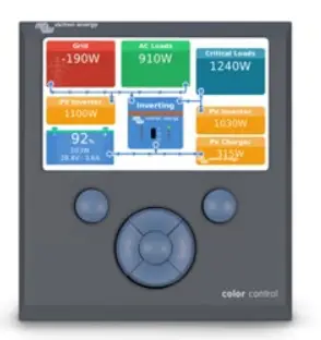
Computer controlled operation and monitoring
Digital Multi Control Panel 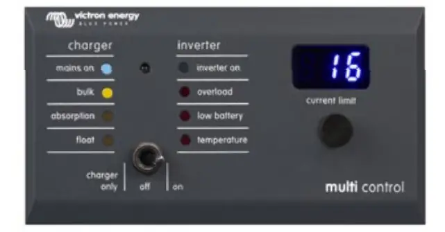
A convenient and low cost solution for remote monitoring, with a rotary knob to set PowerControl and PowerAssist levels.
VE.Bus Smart Dongle
Measures battery voltage and temperature and allows monitoring and control of Multis and Quattros with a smartphone or other Bluetooth enabled device.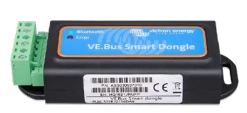
Several interfaces are available
- Color Control GX and other GX devices
Monitoring and control. Locally, and also remotely on the VRM Portal.
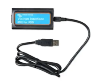
- MK3-USB (VE.Bus to USB interface)
Connects to a USB port (see ‘A guide to VEConfigure’)
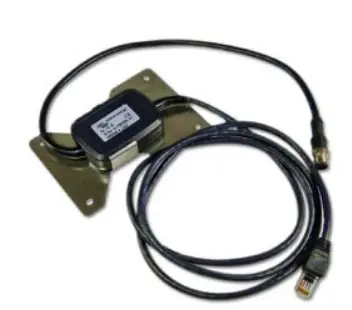
- VE.Bus to NMEA 2000 interface
Connects the device to a NMEA2000 marine electronics network. See the NMEA2000 & MFD integration guide
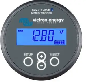
BMV-712 Smart Battery Monitor
Use a smartphone or other Bluetooth enabled device to:
- customize settings,
- monitor all important data on single screen,
- view historical data, and to update the software when new features become available.

Victron Ene rgy B.V.
De Paal 35 | 1351 JG Almere
The Netherlands E-mail: [email protected]
www.victronenergy.com


