![]() 700R11 Indoor Split Geothermal Heat Pump
700R11 Indoor Split Geothermal Heat Pump
033, 042, 050 Variable Speed
User Manual
Submittal Data
English Language/IP Units
SD2703SNA 01/23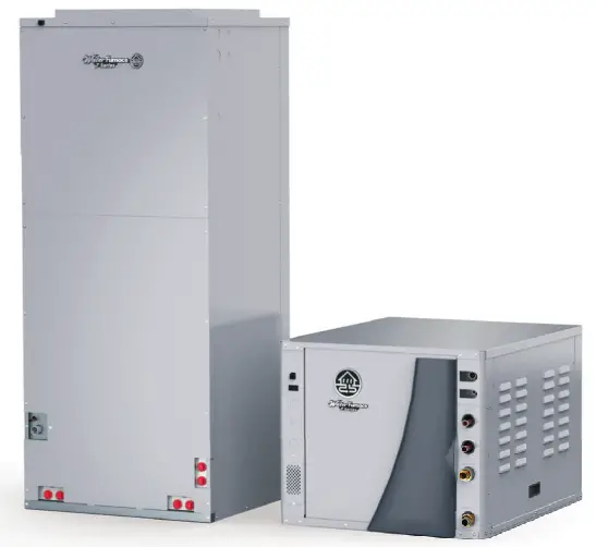
Contractor: P.O.: —————
Engineer: ———————–
Project Name: —————–
Unit Tag: ———————-
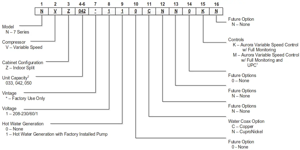
Unit Nomenclature (Compressor Section)
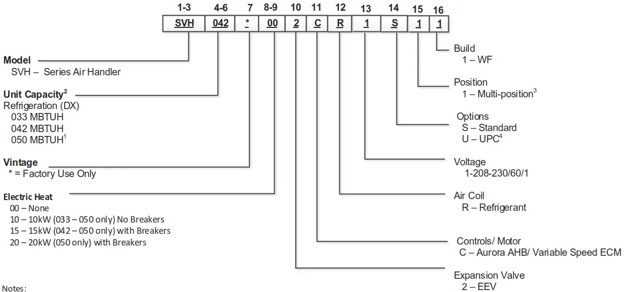
Unit Nomenclature (Air Handler)
Notes:
1 – Air flow on the 050 unit in the horizontal configurations should be limited to 1900 cfm in cooling mode, or condensate blow off may occur.
2 – Compressor section mus t be matched with identical model SVH air handler section. See Compatibility Table
3 – To field convert the SVH to bottom flow air discharge. The SAHBCK kit must be ordered separately.
4 – UPC is not compatible with Symphony or IntelliZone2.
AHRI/ISO 13256-1 Performance Ratings
7 Series Indoor Split Residential Series AHRI Data ECM Motor
AHRI/ASHRAE/ISO 13256-1
| Model | Capacity Modulation | Flow Rate Clg/Htg | Water Loop Heat Pump | Ground Water Heat Pump | Ground Loop Heat Pump | |||||||||
| Cooling EWT 86°F | Heating EWT 68°F | Cooling EWT 59°F | Heating EWT 50°F | Cooling Full Load 77°F Part Load 68°F | Heating Full Load 32°F Part Load 41°F | |||||||||
| cfm | Capacity Btuh | EER Btuh/W | Capacity Btuh | COP | Capacity Btuh | EER Btuh/W | Capacity Btuh | COP | Capacity Btuh | EER Btuh/W | Capacity Btuh | COP | ||
| 033 | Full | 1200/1500 | 31,600 | 16.8 | 49,800 | 5.2 | 37,000 | 29.2 | 40,700 | 4.5 | 33,300 | 20.3 | 31,700 | 3.4 |
| Part | 650/800 | 10,900 | 20.9 | 16,800 | 7.3 | 12,900 | 46.0 | 13,900 | 5.7 | 13,700 | 36.0 | 12,000 | 5.2 | |
| 042 | Full | 1500/1800 | 39,500 | 16.4 | 66,100 | 4.9 | 46,200 | 28.2 | 54,100 | 4.2 | 41,600 | 19.7 | 42,700 | 3.5 |
| Part | 900/1100 | 15,600 | 22.4 | 23,800 | 7.5 | 17,300 | 52.0 | 18,800 | 5.8 | 17,500 | 40.8 | 15,800 | 5.1 | |
| 050 | Full | 1800/2200 | 46,700 | 14.4 | 77,800 | 4.3 | 55,200 | 24.3 | 64,900 | 3.8 | 49,800 | 17.1 | 50,800 | 3.2 |
| Part | 950/1200 | 19,400 | 20.9 | 28,900 | 7.4 | 21,200 | 45.6 | 22,800 | 5.8 | 22,000 | 35.5 | 19,800 | 5.0 | |
3/20/20
Cooling capacities based upon 80.6°F DB, 66.2°F WB entering air temperature Heating capacities based upon 68°F DB, 59°F WB entering air temperature All ratings based upon 208V operation
Energy Star Compliance Table
| Model | Tier 3 | |
| Ground Water | Ground Loop | |
| 033 | Yes | Yes |
| 042 | Yes | Yes |
| 050 | Yes | Yes |
10/31/19
Energy Star Rating Criteria
In order for water-source heat pumps to be Energy Star rated they must meet or exceed the minimum efficiency requirements listed below. Tier 3 represents the current minimum efficiency water source heat pumps must have in order to be Energy Start rated.
Tier 3: 1/1/2012 – No Effective End Date Published
| Water-to-Air | EER C | COP |
| Ground Loop | 17.1 | 3.6 |
| Ground Water | 21.1 | 4.1 |
| Water-to-Water | ||
| Ground Loop | 16.1 | 3.1 |
| Ground Water | 20.1 | 3.5 |
![]()
Compressor Section Dimensional Data
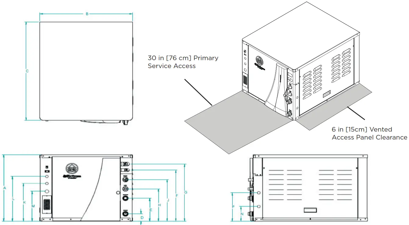
| Models | Height | Width | Depth | Water In | Water Out | Service Valve | HWG In | HWG Out | Low | External | Line | KNOCK OUT | KNOCK OUT | ||
| Liquid | Gas | Voltage | Pump | Voltage | |||||||||||
| A | B | C | D | E | F | G | H | J | K | L | M | N | P | ||
| 033-050 | in. | 21.25 | 25.62 | 31.60 | 2.30 | 7.21 | 16.40 | 18.30 | 10.30 | 13.30 | 12.10 | 14.30 | 9.50 | 4.70 | 9.10 |
| cm. | 54.00 | 65.10 | 80.30 | 5.80 | 18.50 | 41.70 | 46.50 | 26.20 | 33.80 | 30.70 | 36.30 | 24.10 | 11.90 | 23.10 | |
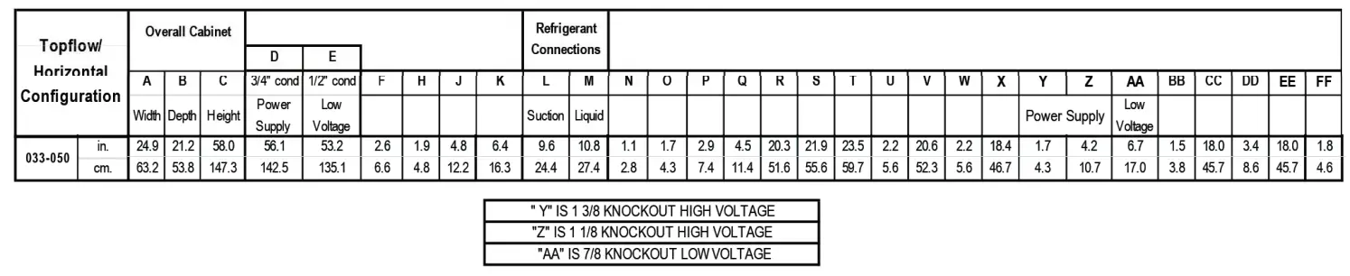
Air Handler Dimensional Data – SVH Air Handler
Top Flow/Horizontal Unit Configuration
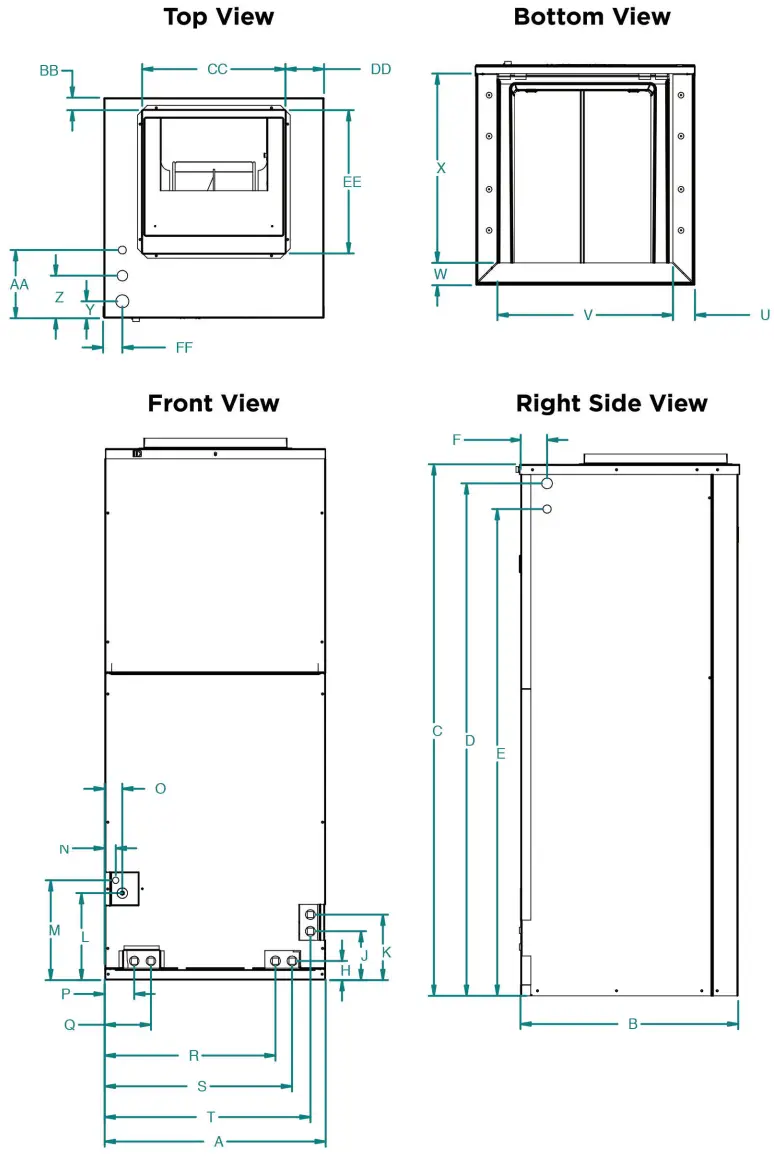
SVH Air Handler – Topflow/Horizontal
Condensate is plastic 3/4″ FPT Discharge flange is field installed and extends 1″ (25.4 mm) from cabinet NOTE: Clearance for maintenance and servicing access – minimum 30″ from front of unit recommended for blower motor/coil replacement. Condensate drain lines routed to clear filter and panel access. Filter removal – minimum 30″ recommended.
Air Handler Dimensional Data – SVH Air Handler
Bottom Flow Unit Configuration
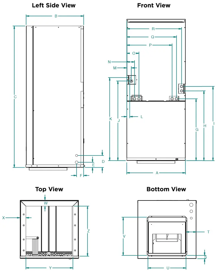
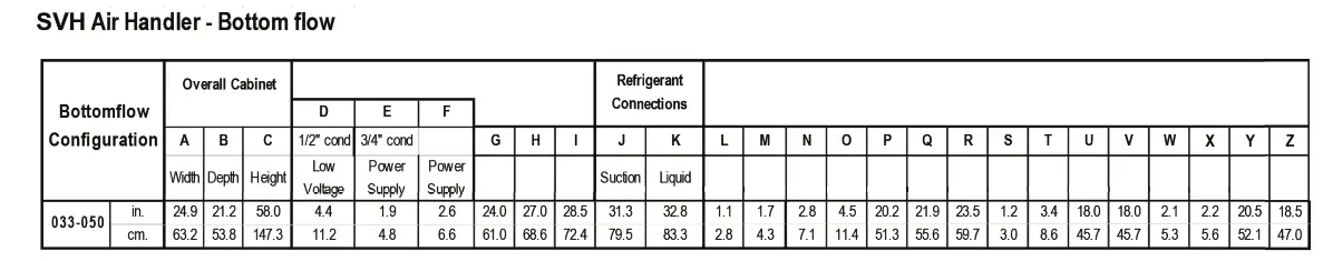
Condensate is plastic 3/4″ FPT Discharge lange is kid installed and extends 1″ (25.4 mm) from cabinet NOTE: Clearance for maintenance and servicing access – minimum 30° from front of unit recommended for blower motor/coil replacement. Condensate drain lines routed to clear filter and panel access. Filter removal – minimum 30° recommended.
Compressor Section Physical Data
| Model | NVZ033 | NVZ042 | NVZ050 | |
| Compressor (1 each) | Variable Speed Scroll | |||
| Factory Charge R410a, oz [kg] | 68 [1.93] | 90 [2.55] | 92 [2.61] | |
| Coax and Water Piping | ||||
| Water Connections Size – Swivel – in [mm] | 1” [25.4] | 1” [25.4] | 1” [25.4] | |
| HWG Connection Size – Female Sweat I.D. – in [mm] | 1/2” [12.7] | 1/2” [12.7] | 1/2” [12.7] | |
| Brass Service Valve – Liquid Line – in [mm] | 3/8” [9.45] | |||
| Brass Service Valve – Suction Line – in [mm] | 3/4” [19.1] | 7/8” [22.23] | ||
| Coax & Piping Water Volume – gal [l] | 1.3 [4.9] | 2.3 [8.7] | 2.3 [8.7] | |
| Weight – Operating, lb [kg] | 241 [109] | 302 [137] | 302 [137] | |
| Weight – Packaged, lb [kg] | 261 [118] | 322 [146] | 322 [146] | |
03/18/20
Notes: All units have an EEV and 1/2 in. [12.7mm], and 3/4 in. [19.1] electrical knockouts Brass services valves are sweat type valves
Air Handler Physical Data
| Air Handler Model Number (Refrigerant) | 033 | 042 | 050 | |
|
Evaporator Coil | Air Coil Total Face Area, ft2 [m2] | 6.81 [0.63] | ||
| Tube outside diameter – in. [mm] | 3/8 [9.52] | |||
| Number of rows | 3 | |||
| Fins per inch | 12 | |||
| Suction line connection – in. [mm] sweat | 7/8 [22.23] | |||
| Liquid line connection – in. [mm] sweat | 3/8 [9.45] | |||
| Refrigerant | R-410a | |||
| Condensate drain connection – (FPT) in. [mm] | 3/4 [19.05] | |||
| Blower Wheel Size (Dia x W), in. [mm] | 11 x 10 [279 x 254] | |||
| Blower motor type/speeds | Variable Speed ECM | |||
| Blower motor output – hp [W] | 1 [746] | |||
| Filter Standard – 1” [51mm] Field Supplied. | 22 X 20 [559 x 508] | |||
| Electrical characteristics (60hz) | 208/230 – 1ph | |||
| Shipping weight – lbs. [kg] | 206 [93.4] | |||
| Operating weight – lbs. [kg] | 188 [85.3] | |||
Auxiliary Heat Compatibility
| Model | kW | Stages | Min CFM | |||
| 033 | 042 | 050 | ||||
| 19P659-02 | 10 | 2 | 1300 | ● | ● | ● |
| 19P659-03 | 15 | 2 | 1700 | ● | ● | |
| 19P659-04 | 20 | 2 | 2000 | ● | ||
03/12/20
Air Handler Auxiliary Heat Blower Settings
| Model | Variable Speed ECM DIP Setting |
| SVH033 | 10 |
| SVH042 | 11 |
| SVH050 | 11 |
6/6/2019
Electrical Data
Variable speed with external loop pump
| Model | Rated Voltage | Voltage Min/Max | COMP LRA | COMP MCC | Drive RLA | Drive Internal Fuse | HWG Pump FLA | Ext Loop FLA | Total Unit FLA | Minimum Circuit Amp | Max Fuse HACR Breaker |
| 033 | 208-230/60/1 | 187/253 | 10.2 | 18.0 | 22.0 | 30.0 | 0.4 | 5.4 | 27.8 | 33.3 | 35 |
| 042 | 208-230/60/1 | 187/253 | 12.0 | 23.5 | 28.0 | 35.0 | 0.4 | 5.4 | 33.8 | 40.8 | 45 |
| 050 | 208-230/60/1 | 187/253 | 12.0 | 30.0 | 33.0 | 40.0 | 0.4 | 5.4 | 38.8 | 47.1 | 50 |
8/21/19
Rated Voltage of 208/230/60/1 HACR circuit breaker in USA only All fuses Class RK-5
Air Handler Electrical Data
| Model | Electric Heat Capacity | Supply Circuit | Aux. Heat Minimum CFM | Rated Voltage | Voltage Min/Max | Fan Motor FLA | Heater Am- pacity | Total Unit FLA | Minimum Circuit Am- pacity | Maximum Fuse/HACR | |||||
| KW | BTUH | ||||||||||||||
| 240v | 240v | 208v | 240v | 208v | 240v | 208v | 240v | 208v | 240v | ||||||
| 033 | 0 | 0 | – |
208- 30/60/1 |
197/253 | 7.0 | – | – | 7.0 | 7.0 | 8.8 | 8.8 | 15 | 15 | |
| 9.6 | 32,765 | single | 1,300 | 7.0 | 34.7 | 40.0 | 41.7 | 47.0 | 52.1 | 58.8 | 60 | 60 | |||
|
042 | 0 | 0 | – | 7.0 | – | – | 7.0 | 7.0 | 8.8 | 8.8 | 15 | 15 | |||
| 9.6 | 32,765 | single | 1,300 | 7.0 | 34.7 | 40.0 | 41.7 | 47.0 | 52.1 | 58.8 | 60 | 60 | |||
| 14.4 | 49,147 | single | 1,700 | 7.0 | 52.0 | 60.0 | 59.0 | 67.0 | 73.8 | 83.8 | 80 | 90 | |||
| 14.4 | 49,147 | L1/L2 | 7.0 | 34.7 | 40.0 | 41.7 | 47.0 | 52.1 | 58.8 | 60 | 60 | ||||
| L3/L4 | – | 17.3 | 20.0 | 17.3 | 20.0 | 21.6 | 25.0 | 25 | 25 | ||||||
|
050 | 0 | 0 | – | 7.0 | – | – | 7.0 | 7.0 | 8.8 | 8.8 | 15 | 15 | |||
| 9.6 | 32,765 | single | 1,300 | 7.0 | 34.7 | 40.0 | 41.7 | 47.0 | 52.1 | 58.8 | 60 | 60 | |||
| 14.4 | 49,147 | single | 1,700 | 7.0 | 52.0 | 60.0 | 59.0 | 67.0 | 73.8 | 83.8 | 80 | 90 | |||
| 14.4 | 49,147 | L1/L2 | 7.0 | 34.7 | 40.0 | 41.7 | 47.0 | 52.1 | 58.8 | 60 | 60 | ||||
| L3/L4 | – | 17.3 | 20.0 | 17.3 | 20.0 | 21.6 | 25.0 | 25 | 25 | ||||||
| 19.2 | 65,530 | single | 2,000 | 7.0 | 69.3 | 80.0 | 76.3 | 87.0 | 95.4 | 108.8 | 100 | 110 | |||
| 19.2 | 65,530 | L1/L2 | 7.0 | 34.7 | 40.0 | 41.7 | 47.0 | 52.1 | 58.8 | 60 | 60 | ||||
| L3/L4 | – | 34.7 | 40.0 | 34.7 | 40.0 | 43.4 | 50.0 | 50 | 50 | ||||||
1/29/20
Rated Voltage of 208/230/60/1 HACR circuit breaker in USA only
SVH Blower Performance Data
Variable Speed ECM
| Model | Max ESP | Speed 1 | Speed 2 | Speed 3 | Speed 4 | Speed 5 | Speed 6 | Speed 7 | Speed 8 | Speed 9 | Speed 10 | Speed 11 | Speed 12 |
| 033 | 0.75 | 250 | 400 G | 550 L | 650 | 750 | 850 | 1000 | 1150 | 1250 H | 1350 Aux | 1450 | 1600 |
| 042 | 0.75 | 250 | 450 G | 650 L | 800 | 950 | 1050 | 1200 | 1350 | 1450 | 1600 H | 1750 Aux | 1850 |
| 050 | 0.75 | 300 | 550 G | 800 L | 1000 | 1150 | 1300 | 1450 | 1600 | 1750 | 1900 H | 2050 Aux | 2200 |
| **VS Com- pressor Speed | 1-2 | 3-4 | 5-6 | 7-8 | 9-10 | 11-12 |
4/15/2020
** VS Compressor speed is given for the factory default cfm settings. When the cfm default settings are changed it will change the relationship to the compressor speed that is shown in the table. In cooling mode compressor speeds 10-12 are only available when SuperBoost mode is selected at the thermostat.
Factory settings are at recommended G, L , H and Aux positions
“G” may be located anywhere within the airflow table.
“L” setting should be located within the boldface CFM range
“H” setting MUST be located within the shaded CFM range
“Aux” setting MUST be equal to or higher than factory setting shown in the table above CFM is controlled within 5% up to the maximum ESP
Line Set Sizes
NOTE: Manufacturer recommends the standard total line set length not to exceed 80 ft with no more than 25 ft of vertical separation between the compressor section and the air handler. For installations that exceed the standard range refer to the Long Line Set Application Guide AG2200EW for further installation requirements.
| Unit | Air | 20 feet | 40 feet | 60 feet | 80 feet | NZ Factory Charge (oz.) | *Charge Amount with SVH Air Handler (oz.) | ||||
| Size | Handler | Suction | Liquid | Suction | Liquid | Suction | Liquid | Suction | Liquid | ||
| NVZ033 | SVH033 | 3/4” OD | 3/8” OD | 3/4” OD | 3/8” OD | 3/4” OD | 3/8” OD | 3/4” OD | 3/8” OD | 68 | 118 |
| NVZ042 | SVH042 | 3/4” OD | 3/8” OD | 3/4” OD | 3/8” OD | 3/4” OD | 3/8” OD | 3/4” OD | 3/8” OD | 90 | 142 |
| NVZ050 | SVH050 | 3/4” OD | 3/8” OD | 3/4” OD | 3/8” OD | 3/4” OD | 3/8” OD | 7/8” OD | 3/8” OD | 92 | 152 |
| CAPACITY MULTIPLIER | 1.00 | 0.985 | 0.97 | 0.955 | |||||||
Notes: * The “Charge Amount with SVH Air Handler” column is based on the charge amount for a SVH Air Handler + Compressor Section/Split. Additional charge will need to be added accordingly for line set length. After charge is added, additional adjustments can be made to get appropriate subcooling and superheat measurements. Additional charge for R410A is 0.50 oz. per ft. for 3/8” and 1.0 oz. per ft. for 1/2” tube. Longer line sets will significantly reduce capacity and efficiency of the system as well as adversely effect the system reliability due to poor oil return.
Operating Limits
| Operating Limits | Cooling | Heating | ||
| (°F) | (°C) | (°F) | (°C) | |
| Air Limits | ||||
| Min. Ambient Air | 45 | 7.2 | 45 | 7.2 |
| Rated Ambient Air | 80 | 26.7 | 70 | 21.1 |
| Max. Ambient Air | 100 | 37.8 | 85 | 29.4 |
| Min. Entering Air | 50 | 10.0 | 40 | 4.4 |
| Rated Entering Air db/wb | 80.6/66.2 | 27/19 | 68 | 20.0 |
| Max. Entering Air db/wb | 110/83 | 43/28.3 | 80 | 26.7 |
| Water Limits | ||||
| Min. Entering Water | 30 | -1.1 | 20 | -6.7 |
| Normal Entering Water | 50-110 | 10-43.3 | 30-70 | -1.1 |
| Max. Entering Water | 120 | 48.9 | 90 | 32.2 |
NOTE: Minimum/maximum limits are only for start-up conditions, and are meant for bringing the space up to occupancy temperature. Units are not designed to operate at the minimum/maximum conditions on a regular basis. The operating limits are dependent upon three primary factors: 1) water temperature, 2) return air temperature, and 3) ambient temperature. When any of the factors are at the minimum or maximum levels, the other two factors must be at the normal level for proper and reliable unit operation.
Definitions
Abbreviations and Definitions
cfm = airflow, cubic feet/minute
EWT = entering water temperature, Fahrenheit
gpm = water flow in gallons/minute
WPD = water pressure drop, psi and feet of water
EAT = entering air temperature, Fahrenheit (dry bulb/wet bulb)
HC = air heating capacity, MBtu/h
TC = total cooling capacity, MBtu/h
SC = sensible cooling capacity, MBtu/h
kW = total power unit input, kilowatts
HR = total heat of rejection, MBtu/h
HE = total heat of extraction, MBtu/h
HWC = hot water generator capacity, MBtu/h
EER = Energy Efficient Ratio
= Btu output/Watt input
COP = Coefficient of Performance
= Btu output/Btu input
LWT = leaving water temperature, °F
LAT = leaving air temperature, °F
TH = total heating capacity, MBtu/h
LC = latent cooling capacity, MBtu/h
S/T = sensible to total cooling ratio
Compressor Section Pressure Drop
| Model | GPM | Pressure Drop (psi) | ||||
| 30° F | 50° F | 70° | 90° F | 110° F | ||
| 033 | 11.5 | 3.60 | 3.30 | 3.10 | 2.90 | 2.70 |
| 9.0 | 2.30 | 2.10 | 2.00 | 1.90 | 1.70 | |
| 7.0 | 2.10 | 2.00 | 1.80 | 1.80 | 1.60 | |
| 6.0 | 1.10 | 1.05 | 1.00 | 0.90 | 0.85 | |
| 4.5 | 0.70 | 0.66 | 0.64 | 0.60 | 0.55 | |
| 042 | 13.5 | 4.10 | 3.80 | 3.60 | 3.40 | 3.10 |
| 10.5 | 1.90 | 1.80 | 1.70 | 1.60 | 1.50 | |
| 7.5 | 1.70 | 1.50 | 1.40 | 1.30 | 1.20 | |
| 6.0 | 1.00 | 0.90 | 0.80 | 0..7 | 0.60 | |
| 4.0 | 0.40 | 0.38 | 0.36 | 0.34 | 0.30 | |
| 050 | 17.0 | 6.20 | 5.80 | 5.40 | 5.00 | 4.60 |
| 13.5 | 3.90 | 3.70 | 3.50 | 3.10 | 2.90 | |
| 9.5 | 1.90 | 1.80 | 1.70 | 1.60 | 1.50 | |
| 7.5 | 1.40 | 1.30 | 1.20 | 1.10 | 0.90 | |
| 5.0 | 0.60 | 0.55 | 0.50 | 0.45 | 0.40 | |
8/21/2019
Thermistor Resistance
| Thermistor Resistance (10k Ohm) for FP1, FP2, HWL, LWT and LLT (EWT with Performance Option) | Thermistor Resistance (1k Ohm) for compressor discharge line, suction line, LAT, compressor ambient and EWT | ||
| Thermistor Temperature (°F) | Thermistor Resistance (Ohms) | Thermistor Temperature (°F) | Thermistor Resistance (Ohms) |
| 5 | 75757-70117 | 20 | 974.4-973.4 |
| 14 | 57392-53234 | 25 | 985.4-984.4 |
| 23 | 43865-40771 | 30 | 996.1-995.1 |
| 32 | 33809-31487 | 35 | 1007.0-1006.0 |
| 41 | 26269-24513 | 40 | 1017.8-1016.8 |
| 50 | 20570-19230 | 45 | 1028.6-1027.6 |
| 59 | 16226-15196 | 50 | 1039.5-1038.5 |
| 68 | 12889-12093 | 55 | 1050.2-1049.2 |
| 77 | 10310-9688 | 60 | 1061.2-1060.2 |
| 86 | 8300-7812 | 65 | 1072.9-1071.9 |
| 95 | 6723-6337 | 70 | 1082.7-1081.7 |
| 104 | 5480-5172 | 75 | 1093.4-1092.4 |
| 113 | 4490-4246 | 80 | 1103.0-1102.0 |
| 122 | 3700-3504 | 85 | 1115.5-1114.5 |
| 131 | 3067-2907 | 90 | 1126.2-1125.2 |
| 140 | 2554-2424 | 95 | 1136.6-1135.6 |
| 149 | 2149-2019 | 100 | 1147.2-1146.2 |
| 4/24/12 | 105 | 1158.1-1157.1 | |
| 110 | 1168.8-1167.8 | ||
| 115 | 1179.4-1178.4 | ||
| 120 | 1190.1-1189.1 | ||
| 125 | 1200.3-1199.3 | ||
| 130 | 1212.2-1211.2 | ||
Correction Factor Tables
Air Flow Corrections (Compressor Speeds 1-3)
| Airflow | Cooling | Heating | ||||||
| CFM Per Ton of Clg | % of Nominal | Total Cap | Sens Cap | Power | Heat of Rej | Htg Cap | Power | Heat of Ext |
| 240 | 60 | 0.940 | 0.740 | 0.967 | 0.951 | 0.943 | 1.106 | 0.902 |
| 275 | 69 | 0.950 | 0.783 | 0.973 | 0.959 | 0.953 | 1.088 | 0.918 |
| 300 | 75 | 0.960 | 0.827 | 0.978 | 0.967 | 0.962 | 1.070 | 0.935 |
| 325 | 81 | 0.970 | 0.870 | 0.984 | 0.975 | 0.972 | 1.053 | 0.951 |
| 350 | 88 | 0.980 | 0.913 | 0.989 | 0.984 | 0.981 | 1.035 | 0.967 |
| 375 | 94 | 0.990 | 0.957 | 0.995 | 0.992 | 0.991 | 1.018 | 0.984 |
| 400 | 100 | 1.000 | 1.000 | 1.000 | 1.000 | 1.000 | 1.000 | 1.000 |
| 425 | 106 | 1.030 | 1.022 | 1.024 | 1.026 | 1.009 | 0.982 | 1.016 |
| 450 | 113 | 1.060 | 1.045 | 1.048 | 1.051 | 1.019 | 0.965 | 1.033 |
| 475 | 119 | 1.091 | 1.067 | 1.071 | 1.077 | 1.028 | 0.947 | 1.049 |
| 500 | 125 | 1.121 | 1.089 | 1.095 | 1.103 | 1.038 | 0.930 | 1.065 |
| 520 | 130 | 1.151 | 1.111 | 1.110 | 1.129 | 1.047 | 0.912 | 1.082 |
6/29/12
Air Flow Corrections (Compressor Speeds 4-12)
| Airflow | Cooling | Heating | ||||||
| CFM Per Ton of Clg | % of Nominal | Total Cap | Sens Cap | Power | Heat of Rej | Htg Cap | Power | Heat of Ext |
| 240 | 60 | 0.928 | 0.747 | 0.936 | 0.929 | 0.961 | 1.097 | 0.938 |
| 275 | 69 | 0.940 | 0.789 | 0.946 | 0.941 | 0.967 | 1.081 | 0.948 |
| 300 | 75 | 0.952 | 0.831 | 0.957 | 0.953 | 0.974 | 1.064 | 0.959 |
| 325 | 81 | 0.964 | 0.873 | 0.968 | 0.965 | 0.980 | 1.048 | 0.969 |
| 350 | 88 | 0.976 | 0.916 | 0.979 | 0.976 | 0.987 | 1.032 | 0.979 |
| 375 | 94 | 0.988 | 0.958 | 0.989 | 0.988 | 0.993 | 1.016 | 0.990 |
| 400 | 100 | 1.000 | 1.000 | 1.000 | 1.000 | 1.000 | 1.000 | 1.000 |
| 425 | 106 | 1.020 | 1.023 | 1.004 | 1.018 | 1.010 | 0.966 | 1.018 |
| 450 | 113 | 1.056 | 1.042 | 1.008 | 1.035 | 1.020 | 0.932 | 1.036 |
| 475 | 119 | 1.072 | 1.079 | 1.011 | 1.053 | 1.029 | 0.898 | 1.054 |
| 500 | 125 | 1.087 | 1.095 | 1.015 | 1.070 | 1.039 | 0.865 | 1.071 |
| 520 | 130 | 1.099 | 1.113 | 1.019 | 1.088 | 1.049 | 0.831 | 1.089 |
6/14/12
Cooling Capacity Corrections
| Entering Air WB ° F | Total Clg Cap | Sensible Cooling Capacity Multipliers – Entering DB ° F | Power Input | Heat of Rejection | |||||||||
| 60 | 65 | 70 | 75 | 80 | 80.6 | 85 | 90 | 95 | 100 | ||||
| 55 | 0.898 | 0.723 | 0.866 | 1.048 | 1.185 | * | * | * | * | * | * | 0.985 | 0.913 |
| 60 | 0.912 | 0.632 | 0.880 | 1.078 | 1.244 | 1.260 | * | * | * | * | 0.994 | 0.927 | |
| 63 | 0.945 | 0.768 | 0.960 | 1.150 | 1.175 | * | * | * | * | 0.996 | 0.954 | ||
| 65 | 0.976 | 0.694 | 0.881 | 1.079 | 1.085 | 1.270 | * | * | * | 0.997 | 0.972 | ||
| 66.2 | 0.983 | 0.655 | 0.842 | 1.040 | 1.060 | 1.232 | * | * | * | 0.999 | 0.986 | ||
| 67 | 1.000 | 0.616 | 0.806 | 1.000 | 1.023 | 1.193 | 1.330 | 1.480 | * | 1.000 | 1.000 | ||
| 70 | 1.053 | 0.693 | 0.879 | 0.900 | 1.075 | 1.205 | 1.404 | * | 1.003 | 1.044 | |||
| 75 | 1.168 | 0.687 | 0.715 | 0.875 | 1.040 | 1.261 | 1.476 | 1.007 | 1.141 | ||||
1/5/2017
NOTE: *Sensible capacity equals total capacity at conditions shown.
Heating Capacity Corrections
| Ent Air DB °F | Heating Corrections | ||
| Htg Cap | Power | Heat of Ext | |
| 45 | 1.062 | 0.739 | 1.158 |
| 50 | 1.050 | 0.790 | 1.130 |
| 55 | 1.037 | 0.842 | 1.096 |
| 60 | 1.025 | 0.893 | 1.064 |
| 65 | 1.012 | 0.945 | 1.030 |
| 68 | 1.005 | 0.976 | 1.012 |
| 70 | 1.000 | 1.000 | 1.000 |
| 75 | 0.987 | 1.048 | 0.970 |
| 80 | 0.975 | 1.099 | 0.930 |
Antifreeze Corrections
Catalog performance can be corrected for antifreeze use. Please use the following table and note the example given.
| Antifreeze Type | Antifreeze % by wt | Heating | Cooling | Pressure Drop |
| EWT – °F [°C] | 30 [-1.1] | 90 [32.2] | 30 [-1.1] | |
| Water | 0 | 1.000 | 1.000 | 1.000 |
|
Ethylene Glycol | 10 | 0.973 | 0.991 | 1.075 |
| 20 | 0.943 | 0.979 | 1.163 | |
| 30 | 0.917 | 0.965 | 1.225 | |
| 40 | 0.890 | 0.955 | 1.324 | |
| 50 | 0.865 | 0.943 | 1.419 | |
|
Propylene Glycol | 10 | 0.958 | 0.981 | 1.130 |
| 20 | 0.913 | 0.969 | 1.270 | |
| 30 | 0.854 | 0.950 | 1.433 | |
| 40 | 0.813 | 0.937 | 1.614 | |
| 50 | 0.770 | 0.922 | 1.816 | |
|
Ethanol | 10 | 0.927 | 0.991 | 1.242 |
| 20 | 0.887 | 0.972 | 1.343 | |
| 30 | 0.856 | 0.947 | 1.383 | |
| 40 | 0.815 | 0.930 | 1.523 | |
| 50 | 0.779 | 0.911 | 1.639 | |
|
Methanol | 10 | 0.957 | 0.986 | 1.127 |
| 20 | 0.924 | 0.970 | 1.197 | |
| 30 | 0.895 | 0.951 | 1.235 | |
| 40 | 0.863 | 0.936 | 1.323 | |
| 50 | 0.833 | 0.920 | 1.399 |
![]() WARNING: Gray area represents antifreeze concentrations greater than 35% by weight and should be avoided due to the extreme performance penalty they represent.
WARNING: Gray area represents antifreeze concentrations greater than 35% by weight and should be avoided due to the extreme performance penalty they represent.
Antifreeze Correction Example
Antifreeze solution is Propylene Glycol 20% by weight. Determine the corrected heating and cooling performance at 30°F and 90°F respectively as well as pressure drop at 30°F for a 033 operating at 100% capacity.
The corrected cooling capacity at 90°F would be: 30,500 Btu/h x 0.969 = 29,554 Btu/h
The corrected heating capacity at 30°F would be: 34,100 Btu/h x 0.913 = 31,133 Btu/h
The corrected pressure drop at 30°F and 11.5 gpm would be: 7.9 feet of head x 1.270 = 10.03 feet of head
Performance Data
NVZ033 – 50% Part Load
| EWT °F | Flow gpm | WPD | HEATING – EAT 70°F | EWT °F | Flow gpm | WPD | COOLING – EAT 80/67 °F | |||||||||||||||
| PSI | FT | Airflow cfm | HC MBtuh | Power kW | HE MBtuh | LAT °F | COP | HWC MBtuh | PSI | FT | Airflow cfm | TC MBtuh | SC MBtuh | S/T Ratio | Power kW | HR MBtuh | EER | HWC MBtuh | ||||
| 20 | 3.0 | 0.5 | 1.1 | Operation not recommended | 20 | 2.5 | 0.2 | 0.5 | Operation not recommended | |||||||||||||
| 4.5 | 0.7 | 1.6 | 3.5 | 0.5 | 1.1 | |||||||||||||||||
| 6.0 | 1.2 | 2.7 | 550 | 12.4 | 1.48 | 7.2 | 90.6 | 2.43 | 2.2 | 4.5 | 0.7 | 1.6 | ||||||||||
| 750 | 12.7 | 1.37 | 8.0 | 85.7 | 2.72 | 1.9 | ||||||||||||||||
|
30 | 3.0 | 0.5 | 1.1 | 550 | 13.1 | 1.22 | 8.3 | 91.0 | 3.00 | 2.0 |
30 | 2.5 | 0.2 | 0.5 | 500 | 17.8 | 12.8 | 0.72 | 0.54 | 18.8 | 31.6 | – |
| 750 | 13.6 | 1.25 | 8.7 | 86.1 | 3.04 | 1.7 | 650 | 18.1 | 14.0 | 0.77 | 0.56 | 19.2 | 30.9 | – | ||||||||
| 4.5 | 0.7 | 1.6 | 550 | 13.4 | 1.23 | 8.6 | 91.6 | 3.06 | 2.1 | 3.5 | 0.5 | 1.1 | 500 | 18.0 | 12.9 | 0.71 | 0.51 | 18.9 | 33.7 | – | ||
| 750 | 14.0 | 1.26 | 9.0 | 86.5 | 3.11 | 1.8 | 650 | 18.3 | 14.1 | 0.77 | 0.54 | 19.3 | 32.5 | – | ||||||||
| 6.0 | 1.1 | 2.6 | 550 | 14.6 | 1.39 | 9.0 | 93.1 | 2.89 | 2.2 | 4.5 | 0.7 | 1.6 | 500 | 18.1 | 12.9 | 0.71 | 0.50 | 19.0 | 34.9 | – | ||
| 750 | 14.9 | 1.29 | 9.8 | 87.5 | 3.23 | 1.9 | 650 | 18.6 | 14.1 | 0.76 | 0.52 | 19.5 | 34.0 | – | ||||||||
|
40 | 3.0 | 0.4 | 1.0 | 550 | 15.6 | 1.27 | 11.0 | 95.8 | 3.55 | 2.0 |
40 | 2.5 | 0.2 | 0.5 | 500 | 19.3 | 13.2 | 0.68 | 0.59 | 20.4 | 31.1 | – |
| 750 | 16.2 | 1.29 | 11.5 | 89.6 | 3.60 | 1.8 | 650 | 19.7 | 14.5 | 0.73 | 0.62 | 20.9 | 30.5 | – | ||||||||
| 4.5 | 0.7 | 1.5 | 550 | 16.1 | 1.27 | 11.5 | 96.6 | 3.65 | 2.1 | 3.5 | 0.4 | 1.0 | 500 | 19.6 | 13.4 | 0.68 | 0.56 | 20.6 | 33.2 | – | ||
| 750 | 16.7 | 1.29 | 12.0 | 90.2 | 3.71 | 1.9 | 650 | 19.9 | 14.6 | 0.73 | 0.59 | 21.0 | 32.2 | – | ||||||||
| 6.0 | 1.1 | 2.5 | 550 | 17.0 | 1.30 | 12.2 | 98.1 | 3.76 | 2.2 | 4.5 | 0.7 | 1.5 | 500 | 19.7 | 13.4 | 0.68 | 0.55 | 20.6 | 34.5 | – | ||
| 750 | 17.6 | 1.33 | 12.7 | 91.3 | 3.82 | 2.0 | 650 | 20.2 | 14.6 | 0.72 | 0.57 | 21.1 | 33.7 | – | ||||||||
|
50 | 3.0 | 0.4 | 1.0 | 550 | 18.2 | 1.31 | 13.7 | 100.6 | 4.06 | 2.5 |
50 | 2.5 | 0.2 | 0.5 | 500 | 20.6 | 13.2 | 0.64 | 0.63 | 21.8 | 31.2 | – |
| 750 | 18.8 | 1.33 | 14.2 | 93.2 | 4.13 | 2.2 | 650 | 21.2 | 14.7 | 0.69 | 0.64 | 22.4 | 31.4 | – | ||||||||
| 4.5 | 0.6 | 1.5 | 550 | 18.8 | 1.31 | 14.4 | 101.7 | 4.20 | 2.5 | 3.5 | 0.4 | 1.0 | 500 | 20.8 | 13.3 | 0.64 | 0.61 | 21.9 | 32.3 | – | ||
| 750 | 19.4 | 1.33 | 14.9 | 94.0 | 4.28 | 2.3 | 650 | 21.4 | 14.7 | 0.69 | 0.63 | 22.5 | 32.6 | – | ||||||||
| 6.0 | 1.1 | 2.5 | 550 | 19.7 | 1.34 | 15.1 | 103.2 | 4.30 | 2.6 | 4.5 | 0.6 | 1.5 | 500 | 21.1 | 13.7 | 0.65 | 0.61 | 22.2 | 33.1 | – | ||
| 750 | 20.3 | 1.36 | 15.7 | 95.1 | 4.37 | 2.4 | 650 | 21.7 | 15.1 | 0.70 | 0.62 | 22.8 | 33.4 | – | ||||||||
|
60 | 3.0 | 0.4 | 1.0 | 550 | 20.7 | 1.33 | 16.1 | 104.8 | 4.55 | 2.7 |
60 | 2.5 | 0.2 | 0.5 | 500 | 20.0 | 13.2 | 0.66 | 0.74 | 21.6 | 25.6 | 1.3 |
| 750 | 21.2 | 1.34 | 16.6 | 96.2 | 4.63 | 2.5 | 650 | 20.5 | 14.6 | 0.71 | 0.76 | 22.1 | 25.9 | 1.4 | ||||||||
| 4.5 | 0.6 | 1.4 | 550 | 21.5 | 1.33 | 17.0 | 106.2 | 4.74 | 2.8 | 3.5 | 0.4 | 1.0 | 500 | 20.2 | 13.3 | 0.66 | 0.72 | 21.7 | 26.6 | 1.2 | ||
| 750 | 22.0 | 1.34 | 17.4 | 97.2 | 4.83 | 2.6 | 650 | 20.7 | 14.7 | 0.71 | 0.74 | 22.2 | 26.8 | 1.3 | ||||||||
| 6.0 | 1.0 | 2.4 | 550 | 22.3 | 1.36 | 17.6 | 107.5 | 4.80 | 2.9 | 4.5 | 0.6 | 1.4 | 500 | 20.5 | 13.6 | 0.66 | 0.72 | 22.0 | 27.2 | 1.1 | ||
| 750 | 22.8 | 1.37 | 18.1 | 98.1 | 4.88 | 2.7 | 650 | 21.1 | 15.1 | 0.72 | 0.73 | 22.5 | 27.5 | 1.2 | ||||||||
|
70 | 3.0 | 0.4 | 0.9 | 550 | 23.1 | 1.35 | 18.5 | 108.9 | 5.03 | 3.1 |
70 | 2.5 | 0.2 | 0.5 | 500 | 19.3 | 13.2 | 0.68 | 0.85 | 21.3 | 21.6 | 1.7 |
| 750 | 23.6 | 1.32 | 19.1 | 99.1 | 5.24 | 2.8 | 650 | 19.9 | 14.6 | 0.73 | 0.87 | 21.9 | 21.7 | 1.8 | ||||||||
| 4.5 | 0.6 | 1.4 | 550 | 24.1 | 1.34 | 19.6 | 110.6 | 5.27 | 3.2 | 3.5 | 0.4 | 0.9 | 500 | 19.5 | 13.2 | 0.68 | 0.83 | 21.4 | 22.3 | 1.6 | ||
| 750 | 24.6 | 1.34 | 20.0 | 100.4 | 5.37 | 2.9 | 650 | 20.0 | 14.6 | 0.73 | 0.85 | 22.0 | 22.5 | 1.7 | ||||||||
| 6.0 | 1.0 | 2.3 | 550 | 24.8 | 1.37 | 20.1 | 111.7 | 5.29 | 3.3 | 4.5 | 0.6 | 1.4 | 500 | 19.8 | 13.6 | 0.68 | 0.82 | 21.7 | 22.9 | 1.5 | ||
| 750 | 25.2 | 1.37 | 20.5 | 101.1 | 5.39 | 2.7 | 650 | 20.4 | 15.0 | 0.74 | 0.84 | 22.3 | 23.1 | 1.7 | ||||||||
|
80 | 3.0 | 0.4 | 0.9 | 550 | 25.4 | 1.34 | 20.9 | 112.8 | 5.57 | 3.7 |
80 | 2.5 | 0.2 | 0.4 | 500 | 18.5 | 12.9 | 0.70 | 0.93 | 20.8 | 18.8 | 2.3 |
| 750 | 25.8 | 1.33 | 21.2 | 101.8 | 5.68 | 3.4 | 650 | 19.0 | 14.3 | 0.75 | 0.95 | 21.3 | 19.0 | 2.5 | ||||||||
| 4.5 | 0.6 | 1.3 | 550 | 26.6 | 1.33 | 22.1 | 114.9 | 5.87 | 3.9 | 3.5 | 0.4 | 0.9 | 500 | 18.6 | 13.0 | 0.69 | 0.91 | 20.9 | 19.5 | 2.2 | ||
| 750 | 27.0 | 1.32 | 22.5 | 103.3 | 5.99 | 3.5 | 650 | 19.2 | 14.3 | 0.75 | 0.93 | 21.4 | 19.7 | 2.4 | ||||||||
| 6.0 | 1.0 | 2.2 | 550 | 27.0 | 1.36 | 22.4 | 115.5 | 5.84 | 4.0 | 4.5 | 0.6 | 1.3 | 500 | 19.0 | 13.3 | 0.70 | 0.90 | 21.1 | 20.0 | 2.0 | ||
| 750 | 27.3 | 1.35 | 22.7 | 103.7 | 5.95 | 3.7 | 650 | 19.5 | 14.7 | 0.75 | 0.92 | 21.7 | 20.2 | 2.2 | ||||||||
|
90 | 3.0 | 0.4 | 0.9 | 550 | 27.7 | 1.33 | 23.2 | 116.7 | 6.12 | 4.3 |
90 | 2.5 | 0.2 | 0.4 | 500 | 17.6 | 12.6 | 0.71 | 1.02 | 20.3 | 16.5 | 3.0 |
| 750 | 27.9 | 1.31 | 23.5 | 104.5 | 6.25 | 4.0 | 650 | 18.1 | 13.9 | 0.77 | 1.04 | 20.8 | 16.7 | 3.2 | ||||||||
| 4.5 | 0.6 | 1.3 | 550 | 29.1 | 1.32 | 24.7 | 119.1 | 6.49 | 4.5 | 3.5 | 0.4 | 0.9 | 500 | 17.8 | 12.7 | 0.71 | 0.99 | 20.3 | 17.1 | 2.9 | ||
| 750 | 29.3 | 1.30 | 24.9 | 106.2 | 6.63 | 4.1 | 650 | 18.3 | 14.0 | 0.77 | 1.01 | 20.9 | 17.3 | 3.1 | ||||||||
| 6.0 | 0.9 | 2.2 | 550 | 29.3 | 1.34 | 24.7 | 119.3 | 6.40 | 4.6 | 4.5 | 0.6 | 1.3 | 500 | 17.6 | 12.3 | 0.70 | 1.17 | 20.8 | 14.4 | 2.8 | ||
| 750 | 29.4 | 1.32 | 24.9 | 106.3 | 6.53 | 4.3 | 650 | 18.6 | 14.4 | 0.77 | 1.00 | 21.1 | 17.7 | 2.6 | ||||||||
|
100 | 3.0 | 0.4 | 0.8 |
Operation not recommended |
100 | 2.5 | 0.2 | 0.4 | 500 | 16.7 | 12.4 | 0.74 | 1.34 | 20.5 | 11.9 | 3.6 | ||||||
| 650 | 17.2 | 13.7 | 0.80 | 1.36 | 21.0 | 12.0 | 3.8 | |||||||||||||||
| 4.5 | 0.5 | 1.2 | 3.5 | 0.4 | 0.8 | 500 | 16.9 | 12.4 | 0.74 | 1.30 | 20.5 | 12.4 | 3.3 | |||||||||
| 650 | 17.4 | 13.8 | 0.79 | 1.33 | 21.1 | 12.5 | 3.6 | |||||||||||||||
| 6.0 | 0.9 | 2.1 | 4.5 | 0.5 | 1.2 | 500 | 17.2 | 12.8 | 0.74 | 1.29 | 20.7 | 12.7 | 3.0 | |||||||||
| 650 | 17.6 | 14.1 | 0.80 | 1.32 | 21.3 | 12.8 | 3.4 | |||||||||||||||
|
110 | 3.0 | 0.3 | 0.8 |
110 | 2.5 | 0.2 | 0.4 | 500 | 15.8 | 12.1 | 0.77 | 1.66 | 20.7 | 9.1 | 4.7 | |||||||
| 650 | 16.3 | 13.4 | 0.83 | 1.69 | 21.3 | 9.2 | 5.0 | |||||||||||||||
| 4.5 | 0.5 | 1.2 | 3.5 | 0.3 | 0.8 | 500 | 16.0 | 12.2 | 0.76 | 1.61 | 20.7 | 9.4 | 4.4 | |||||||||
| 650 | 16.4 | 13.5 | 0.82 | 1.64 | 21.3 | 9.5 | 4.8 | |||||||||||||||
| 6.0 | 0.9 | 2.0 | 4.5 | 0.5 | 1.2 | 500 | 16.2 | 12.5 | 0.77 | 1.60 | 20.9 | 9.7 | 4.1 | |||||||||
| 650 | 16.7 | 13.9 | 0.83 | 1.63 | 21.5 | 9.8 | 4.6 | |||||||||||||||
|
120 | 3.0 | 0.3 | 0.8 |
120 | 2.5 | 0.2 | 0.4 | 500 | 13.2 | 12.1 | 0.92 | 1.95 | 19.2 | 6.4 | 6.2 | |||||||
| 650 | 13.5 | 13.2 | 0.98 | 2.00 | 19.6 | 6.4 | 6.0 | |||||||||||||||
| 4.5 | 0.5 | 1.2 | 3.5 | 0.3 | 0.8 | 500 | 13.4 | 12.2 | 0.91 | 1.84 | 19.0 | 6.9 | 5.5 | |||||||||
| 650 | 13.6 | 13.2 | 0.97 | 1.89 | 19.4 | 6.8 | 5.9 | |||||||||||||||
| 6.0 | 0.8 | 1.9 | 4.5 | 0.5 | 1.2 | 500 | 13.5 | 12.2 | 0.90 | 1.78 | 18.9 | 7.2 | 5.0 | |||||||||
| 650 | 13.8 | 13.2 | 0.96 | 1.84 | 19.4 | 7.1 | 5.6 | |||||||||||||||
3/27/2020
Performance Data cont.
NVZ033 – 100% Full Load
| EWT °F | Flow gpm | WPD | HEATING – EAT 70°F | EWT °F | Flow gpm | WPD | COOLING – EAT 80/67 °F | |||||||||||||||
| PSI | FT | Airflow cfm | HC MBtuh | Power kW | HE MBtuh | LAT °F | COP | HWC MBtuh | PSI | FT | Airflow cfm | TC MBtuh | SC MBtuh | S/T Ratio | Power kW | HR MBtuh | EER | HWC MBtuh | ||||
| 20 | 6.0 | 1.5 | 3.5 | Operation not recommended | 20 | 4.5 | 0.7 | 1.6 | Operation not recommended | |||||||||||||
| 9.0 | 2.3 | 5.4 | 6.5 | 1.5 | 3.5 | |||||||||||||||||
| 12.0 | 4.1 | 9.5 | 1150 | 27.6 | 2.94 | 17.6 | 92.2 | 2.75 | 3.0 | 9.0 | 2.3 | 5.4 | ||||||||||
| 1500 | 28.7 | 2.80 | 19.1 | 87.7 | 3.00 | 2.7 | ||||||||||||||||
|
30 | 6.0 | 1.5 | 3.4 | 1150 | 31.7 | 2.70 | 22.5 | 95.5 | 3.44 | 3.1 |
30 | 4.5 | 0.7 | 1.6 | 1000 | 34.6 | 22.1 | 0.64 | 1.14 | 38.5 | 30.4 | – |
| 1500 | 32.6 | 2.79 | 23.1 | 90.1 | 3.42 | 2.8 | 1200 | 35.2 | 24.3 | 0.69 | 1.18 | 39.3 | 29.8 | – | ||||||||
| 9.0 | 2.3 | 5.3 | 1150 | 32.5 | 2.74 | 23.1 | 96.2 | 3.48 | 3.2 | 6.5 | 1.5 | 3.4 | 1000 | 35.1 | 22.3 | 0.64 | 1.08 | 38.7 | 32.5 | – | ||
| 1500 | 33.4 | 2.82 | 23.8 | 90.6 | 3.47 | 2.9 | 1200 | 35.6 | 24.4 | 0.68 | 1.14 | 39.5 | 31.3 | – | ||||||||
| 12.0 | 4.0 | 9.2 | 1150 | 32.8 | 2.99 | 22.6 | 96.4 | 3.22 | 3.2 | 9.0 | 2.3 | 5.3 | 1000 | 35.2 | 22.3 | 0.63 | 1.05 | 38.8 | 33.6 | – | ||
| 1500 | 34.1 | 2.85 | 24.4 | 91.0 | 3.51 | 2.9 | 1200 | 36.1 | 24.4 | 0.68 | 1.10 | 39.9 | 32.8 | – | ||||||||
|
40 | 6.0 | 1.4 | 3.3 | 1150 | 35.4 | 2.84 | 25.7 | 98.5 | 3.66 | 3.3 |
40 | 4.5 | 0.7 | 1.5 | 1000 | 35.4 | 23.6 | 0.67 | 1.31 | 39.9 | 27.1 | – |
| 1500 | 36.5 | 2.91 | 26.5 | 92.5 | 3.67 | 3.1 | 1200 | 36.1 | 25.9 | 0.72 | 1.36 | 40.7 | 26.5 | – | ||||||||
| 9.0 | 2.2 | 5.1 | 1150 | 36.5 | 2.89 | 26.7 | 99.4 | 3.70 | 3.4 | 6.5 | 1.4 | 3.3 | 1000 | 35.8 | 23.9 | 0.67 | 1.24 | 40.1 | 28.8 | – | ||
| 1500 | 37.7 | 2.96 | 27.6 | 93.2 | 3.73 | 3.1 | 1200 | 36.5 | 26.1 | 0.71 | 1.30 | 40.9 | 28.0 | – | ||||||||
| 12.0 | 3.9 | 8.9 | 1150 | 37.3 | 2.92 | 27.3 | 100.0 | 3.74 | 3.5 | 9.0 | 2.2 | 5.1 | 1000 | 36.1 | 23.9 | 0.66 | 1.20 | 40.2 | 30.0 | – | ||
| 1500 | 38.5 | 2.99 | 28.3 | 93.7 | 3.78 | 3.2 | 1200 | 36.9 | 26.1 | 0.71 | 1.26 | 41.2 | 29.3 | – | ||||||||
|
50 | 6.0 | 1.4 | 3.2 | 1150 | 39.2 | 2.98 | 29.0 | 101.5 | 3.85 | 3.7 |
50 | 4.5 | 0.6 | 1.5 | 1000 | 34.7 | 23.1 | 0.66 | 1.47 | 39.7 | 23.6 | – |
| 1500 | 40.3 | 3.02 | 30.0 | 94.9 | 3.91 | 3.4 | 1200 | 36.5 | 25.7 | 0.70 | 1.55 | 41.8 | 23.6 | – | ||||||||
| 9.0 | 2.1 | 4.9 | 1150 | 40.6 | 3.05 | 30.2 | 102.7 | 3.90 | 3.8 | 6.5 | 1.4 | 3.2 | 1000 | 35.5 | 23.4 | 0.66 | 1.39 | 40.2 | 25.6 | – | ||
| 1500 | 41.9 | 3.09 | 31.3 | 95.9 | 3.97 | 3.5 | 1200 | 37.3 | 25.9 | 0.70 | 1.45 | 42.2 | 25.6 | – | ||||||||
| 12.0 | 3.7 | 8.6 | 1150 | 41.5 | 3.08 | 31.0 | 103.4 | 3.95 | 3.9 | 9.0 | 2.1 | 4.9 | 1000 | 35.8 | 24.9 | 0.70 | 1.35 | 40.4 | 26.5 | – | ||
| 1500 | 42.8 | 3.12 | 32.2 | 96.4 | 4.02 | 3.6 | 1200 | 37.7 | 27.7 | 0.73 | 1.42 | 42.5 | 26.5 | – | ||||||||
|
60 | 6.0 | 1.3 | 3.1 | 1150 | 43.4 | 3.03 | 33.1 | 105.0 | 4.20 | 4.1 |
60 | 4.5 | 0.6 | 1.4 | 1000 | 32.9 | 23.4 | 0.71 | 1.68 | 38.6 | 19.6 | 1.9 |
| 1500 | 44.8 | 3.05 | 34.4 | 97.7 | 4.31 | 3.8 | 1200 | 34.5 | 26.0 | 0.75 | 1.75 | 40.4 | 19.7 | 2.1 | ||||||||
| 9.0 | 2.1 | 4.8 | 1150 | 45.4 | 3.11 | 34.7 | 106.5 | 4.27 | 4.3 | 6.5 | 1.3 | 3.1 | 1000 | 33.6 | 23.7 | 0.70 | 1.59 | 39.1 | 21.1 | 1.8 | ||
| 1500 | 46.8 | 3.13 | 36.1 | 98.9 | 4.38 | 3.9 | 1200 | 35.2 | 26.2 | 0.74 | 1.66 | 40.9 | 21.2 | 2.0 | ||||||||
| 12.0 | 3.6 | 8.4 | 1150 | 46.5 | 3.15 | 35.7 | 107.4 | 4.33 | 4.4 | 9.0 | 2.1 | 4.8 | 1000 | 34.0 | 24.9 | 0.73 | 1.55 | 39.3 | 21.9 | 1.7 | ||
| 1500 | 48.0 | 3.16 | 37.2 | 99.6 | 4.45 | 4.0 | 1200 | 35.7 | 27.7 | 0.78 | 1.63 | 41.2 | 21.9 | 1.9 | ||||||||
|
70 | 6.0 | 1.3 | 3.0 | 1150 | 47.7 | 3.07 | 37.2 | 108.4 | 4.55 | 4.6 |
70 | 4.5 | 0.6 | 1.4 | 1000 | 31.0 | 23.7 | 0.76 | 1.92 | 37.6 | 16.2 | 2.4 |
| 1500 | 49.1 | 3.15 | 38.4 | 100.3 | 4.57 | 4.3 | 1200 | 32.1 | 25.4 | 0.79 | 1.98 | 38.9 | 16.2 | 2.5 | ||||||||
| 9.0 | 2.0 | 4.6 | 1150 | 50.2 | 3.17 | 39.3 | 110.4 | 4.63 | 4.8 | 6.5 | 1.3 | 3.0 | 1000 | 31.8 | 24.0 | 0.75 | 1.80 | 38.0 | 17.7 | 2.2 | ||
| 1500 | 51.8 | 3.17 | 41.0 | 102.0 | 4.78 | 4.4 | 1200 | 33.2 | 26.5 | 0.80 | 1.87 | 39.6 | 17.8 | 2.4 | ||||||||
| 12.0 | 3.5 | 8.1 | 1150 | 51.4 | 3.21 | 40.5 | 111.4 | 4.69 | 4.9 | 9.0 | 2.0 | 4.6 | 1000 | 32.2 | 24.9 | 0.77 | 1.76 | 38.2 | 18.3 | 2.0 | ||
| 1500 | 53.2 | 3.20 | 42.3 | 102.8 | 4.87 | 4.5 | 1200 | 33.6 | 27.6 | 0.82 | 1.83 | 39.8 | 18.4 | 2.3 | ||||||||
|
80 | 6.0 | 1.3 | 2.9 | 1150 | 51.0 | 3.18 | 40.1 | 111.1 | 4.70 | 5.2 |
80 | 4.5 | 0.6 | 1.3 | 1000 | 29.6 | 23.5 | 0.79 | 2.14 | 36.9 | 13.8 | 2.9 |
| 1500 | 52.8 | 3.16 | 42.0 | 102.6 | 4.90 | 4.9 | 1200 | 30.8 | 26.2 | 0.85 | 2.21 | 38.4 | 14.0 | 3.1 | ||||||||
| 9.0 | 1.9 | 4.5 | 1150 | 53.9 | 3.31 | 42.7 | 113.4 | 4.78 | 5.4 | 6.5 | 1.3 | 2.9 | 1000 | 30.5 | 23.8 | 0.78 | 2.07 | 37.5 | 14.7 | 2.7 | ||
| 1500 | 55.8 | 3.27 | 44.6 | 104.4 | 4.99 | 5.0 | 1200 | 31.7 | 26.4 | 0.83 | 2.13 | 38.9 | 14.9 | 3.0 | ||||||||
| 12.0 | 3.4 | 7.8 | 1150 | 55.5 | 3.35 | 44.1 | 114.7 | 4.86 | 5.6 | 9.0 | 1.9 | 4.5 | 1000 | 30.8 | 24.4 | 0.79 | 2.02 | 37.7 | 15.2 | 2.5 | ||
| 1500 | 57.4 | 3.30 | 46.1 | 105.4 | 5.10 | 5.1 | 1200 | 32.1 | 27.1 | 0.84 | 2.09 | 39.2 | 15.4 | 2.8 | ||||||||
|
90 | 6.0 | 1.2 | 2.8 | 1150 | 54.3 | 3.29 | 43.1 | 113.7 | 4.84 | 5.9 |
90 | 4.5 | 0.6 | 1.3 | 1000 | 28.3 | 23.4 | 0.83 | 2.40 | 36.4 | 11.8 | 3.7 |
| 1500 | 56.2 | 3.24 | 45.2 | 104.7 | 5.09 | 5.5 | 1200 | 29.3 | 26.0 | 0.89 | 2.46 | 37.6 | 11.9 | 3.9 | ||||||||
| 9.0 | 1.9 | 4.3 | 1150 | 57.7 | 3.44 | 46.0 | 116.5 | 4.92 | 6.1 | 6.5 | 1.2 | 2.8 | 1000 | 29.1 | 23.7 | 0.82 | 2.33 | 37.0 | 12.5 | 3.4 | ||
| 1500 | 59.8 | 3.38 | 48.3 | 106.9 | 5.19 | 5.7 | 1200 | 30.2 | 26.3 | 0.87 | 2.39 | 38.3 | 12.6 | 3.7 | ||||||||
| 12.0 | 3.3 | 7.5 | 1150 | 59.6 | 3.49 | 47.7 | 117.9 | 5.01 | 6.3 | 9.0 | 1.9 | 4.3 | 1000 | 29.8 | 24.0 | 0.81 | 2.33 | 37.7 | 12.8 | 3.2 | ||
| 1500 | 61.6 | 3.40 | 50.0 | 108.0 | 5.31 | 5.8 | 1200 | 30.5 | 26.5 | 0.87 | 2.34 | 38.5 | 13.0 | 4.1 | ||||||||
|
100 | 6.0 | 1.2 | 2.7 |
Operation not recommended |
100 | 4.5 | 0.5 | 1.2 | 1000 | 26.8 | 23.2 | 0.87 | 2.73 | 36.1 | 9.8 | 4.4 | ||||||
| 1200 | 27.6 | 25.7 | 0.93 | 2.78 | 37.1 | 9.9 | 4.8 | |||||||||||||||
| 9.0 | 1.8 | 4.2 | 6.5 | 1.2 | 2.7 | 1000 | 27.7 | 23.5 | 0.85 | 2.68 | 36.8 | 10.3 | 4.1 | |||||||||
| 1200 | 28.6 | 26.1 | 0.91 | 2.72 | 37.9 | 10.5 | 4.5 | |||||||||||||||
| 12.0 | 3.1 | 7.3 | 9.0 | 1.8 | 4.2 | 1000 | 28.0 | 23.4 | 0.84 | 2.63 | 37.0 | 10.6 | 3.8 | |||||||||
| 1200 | 28.9 | 25.9 | 0.90 | 2.68 | 38.0 | 10.8 | 4.3 | |||||||||||||||
|
110 | 6.0 | 1.1 | 2.6 |
110 | 4.5 | 0.5 | 1.2 | 1000 | 25.3 | 23.0 | 0.91 | 3.06 | 35.8 | 8.3 | 5.6 | |||||||
| 1200 | 26.0 | 25.5 | 0.98 | 3.10 | 36.6 | 8.4 | 5.9 | |||||||||||||||
| 9.0 | 1.7 | 4.0 | 6.5 | 1.1 | 2.6 | 1000 | 26.3 | 23.2 | 0.88 | 3.03 | 36.7 | 8.7 | 5.2 | |||||||||
| 1200 | 27.0 | 25.8 | 0.96 | 3.05 | 37.4 | 8.9 | 5.6 | |||||||||||||||
| 12.0 | 3.0 | 7.0 | 9.0 | 1.7 | 4.0 | 1000 | 26.6 | 22.9 | 0.86 | 2.98 | 36.7 | 8.9 | 4.8 | |||||||||
| 1200 | 27.3 | 25.3 | 0.93 | 3.01 | 37.6 | 9.1 | 5.3 | |||||||||||||||
|
120 | 6.0 | 1.1 | 2.5 |
120 | 4.5 | 0.5 | 1.2 | 1000 | 24.4 | 22.1 | 0.90 | 3.60 | 36.7 | 6.8 | 6.7 | |||||||
| 1200 | 25.0 | 24.1 | 0.97 | 3.69 | 37.5 | 6.8 | 7.1 | |||||||||||||||
| 9.0 | 1.7 | 3.8 | 6.5 | 1.1 | 2.5 | 1000 | 24.7 | 22.3 | 0.90 | 3.41 | 36.4 | 7.3 | 6.2 | |||||||||
| 1200 | 25.2 | 24.2 | 0.96 | 3.49 | 37.1 | 7.2 | 6.7 | |||||||||||||||
| 12.0 | 2.9 | 6.7 | 9.0 | 1.7 | 3.8 | 1000 | 25.0 | 22.3 | 0.89 | 3.30 | 36.2 | 7.6 | 6.4 | |||||||||
| 1200 | 25.5 | 24.2 | 0.95 | 3.40 | 37.1 | 7.5 | 7.1 | |||||||||||||||
Performance Data cont.
NVZ042 – 50% Part Load
| EWT °F | Flow gpm | WPD | HEATING – EAT 70°F | EWT °F | Flow gpm | WPD | COOLING – EAT 80/67 °F | |||||||||||||||
| PSI | FT | Airflow cfm | HC MBtuh | Power kW | HE MBtuh | LAT °F | COP | HWC MBtuh | PSI | FT | Airflow cfm | TC MBtuh | SC MBtuh | S/T Ratio | Power kW | HR MBtuh | EER | HWC MBtuh | ||||
| 20 | 3.7 | 0.4 | 0.8 | Operation not recommended | 20 | 3.0 | 0.2 | 0.5 | Operation not recommended | |||||||||||||
| 5.2 | 0.7 | 1.6 | 4.4 | 0.6 | 1.4 | |||||||||||||||||
| 6.7 | 1.2 | 2.7 | 700 | 16.6 | 1.73 | 10.7 | 91.9 | 2.81 | 2.7 | 5.8 | 0.9 | 2.2 | ||||||||||
| 900 | 16.9 | 1.66 | 11.2 | 87.4 | 2.98 | 2.3 | ||||||||||||||||
|
30 | 3.7 | 0.3 | 0.8 | 700 | 17.1 | 1.56 | 11.8 | 92.6 | 3.20 | 2.6 |
30 | 3.0 | 0.2 | 0.5 | 650 | 23.3 | 15.7 | 0.67 | 0.59 | 24.2 | 37.8 | – |
| 900 | 17.7 | 1.59 | 12.2 | 88.2 | 3.26 | 2.2 | 750 | 23.8 | 17.2 | 0.73 | 0.61 | 24.7 | 36.9 | – | ||||||||
| 5.2 | 0.7 | 1.6 | 700 | 18.5 | 1.63 | 12.9 | 94.4 | 3.31 | 2.7 | 4.4 | 0.6 | 1.3 | 650 | 23.7 | 15.9 | 0.67 | 0.56 | 24.4 | 40.3 | – | ||
| 900 | 19.0 | 1.65 | 13.4 | 89.6 | 3.39 | 2.3 | 750 | 24.0 | 17.3 | 0.72 | 0.59 | 24.9 | 38.8 | – | ||||||||
| 6.7 | 1.1 | 2.6 | 700 | 19.2 | 1.74 | 13.3 | 95.4 | 3.23 | 2.8 | 5.8 | 0.9 | 2.1 | 650 | 23.8 | 15.9 | 0.67 | 0.54 | 24.5 | 41.7 | – | ||
| 900 | 19.6 | 1.67 | 13.9 | 90.2 | 3.44 | 2.4 | 750 | 24.4 | 17.3 | 0.71 | 0.57 | 25.1 | 40.7 | – | ||||||||
|
40 | 3.7 | 0.3 | 0.8 | 700 | 19.9 | 1.60 | 14.4 | 96.3 | 3.64 | 2.8 |
40 | 3.0 | 0.2 | 0.5 | 650 | 24.4 | 16.1 | 0.66 | 0.67 | 25.5 | 34.4 | – |
| 900 | 20.5 | 1.61 | 15.0 | 91.1 | 3.73 | 2.4 | 750 | 24.9 | 17.6 | 0.71 | 0.70 | 26.1 | 33.7 | – | ||||||||
| 5.2 | 0.7 | 1.5 | 700 | 21.4 | 1.66 | 15.8 | 98.4 | 3.78 | 2.9 | 4.4 | 0.6 | 1.3 | 650 | 24.7 | 16.2 | 0.66 | 0.64 | 25.7 | 36.7 | – | ||
| 900 | 22.2 | 1.66 | 16.5 | 92.8 | 3.91 | 2.5 | 750 | 25.1 | 17.7 | 0.70 | 0.67 | 26.2 | 35.6 | – | ||||||||
| 6.7 | 1.1 | 2.5 | 700 | 22.1 | 1.67 | 16.4 | 99.3 | 3.88 | 3.0 | 5.8 | 0.9 | 2.0 | 650 | 24.9 | 16.2 | 0.65 | 0.62 | 25.8 | 38.1 | – | ||
| 900 | 22.9 | 1.69 | 17.2 | 93.6 | 3.98 | 2.6 | 750 | 25.4 | 17.7 | 0.70 | 0.65 | 26.4 | 37.2 | – | ||||||||
|
50 | 3.7 | 0.3 | 0.7 | 700 | 22.7 | 1.64 | 17.1 | 100.0 | 4.06 | 3.1 |
50 | 3.0 | 0.2 | 0.5 | 650 | 25.0 | 15.3 | 0.61 | 0.85 | 26.7 | 27.9 | – |
| 900 | 23.4 | 1.64 | 17.8 | 94.1 | 4.19 | 2.8 | 750 | 25.8 | 18.0 | 0.70 | 0.89 | 27.6 | 27.6 | – | ||||||||
| 5.2 | 0.6 | 1.5 | 700 | 24.4 | 1.69 | 18.7 | 102.3 | 4.24 | 3.3 | 4.4 | 0.5 | 1.2 | 650 | 25.5 | 15.3 | 0.60 | 0.74 | 26.8 | 33.0 | – | ||
| 900 | 25.4 | 1.68 | 19.6 | 96.1 | 4.43 | 2.9 | 750 | 26.3 | 18.1 | 0.69 | 0.77 | 27.7 | 32.4 | – | ||||||||
| 6.7 | 1.1 | 2.5 | 700 | 25.4 | 1.70 | 19.6 | 103.6 | 4.37 | 3.4 | 5.8 | 0.9 | 2.0 | 650 | 25.7 | 15.3 | 0.60 | 0.69 | 26.8 | 35.2 | – | ||
| 900 | 26.2 | 1.70 | 20.4 | 97.0 | 4.52 | 3.0 | 750 | 26.5 | 18.1 | 0.68 | 0.73 | 27.7 | 34.5 | – | ||||||||
|
60 | 3.7 | 0.3 | 0.7 | 700 | 25.2 | 1.68 | 19.4 | 103.3 | 4.39 | 2.9 |
60 | 3.0 | 0.2 | 0.5 | 650 | 23.6 | 15.0 | 0.64 | 0.99 | 25.9 | 22.8 | 1.3 |
| 900 | 26.1 | 1.67 | 20.4 | 96.8 | 4.58 | 2.5 | 750 | 24.4 | 17.7 | 0.73 | 1.03 | 26.7 | 22.5 | 1.5 | ||||||||
| 5.2 | 0.6 | 1.4 | 700 | 27.2 | 1.72 | 21.4 | 106.0 | 4.64 | 3.0 | 4.4 | 0.5 | 1.2 | 650 | 24.0 | 15.1 | 0.63 | 0.88 | 25.9 | 26.1 | 1.2 | ||
| 900 | 28.3 | 1.70 | 22.5 | 99.1 | 4.88 | 2.6 | 750 | 24.8 | 17.8 | 0.72 | 0.92 | 26.7 | 25.7 | 1.4 | ||||||||
| 6.7 | 1.0 | 2.4 | 700 | 28.4 | 1.74 | 22.5 | 107.6 | 4.79 | 3.2 | 5.8 | 0.8 | 1.9 | 650 | 24.3 | 15.2 | 0.62 | 0.83 | 26.0 | 27.8 | 1.1 | ||
| 900 | 29.4 | 1.72 | 23.5 | 100.2 | 5.02 | 2.7 | 750 | 25.0 | 17.9 | 0.71 | 0.87 | 26.8 | 27.4 | 1.3 | ||||||||
|
70 | 3.7 | 0.3 | 0.7 | 700 | 27.7 | 1.72 | 21.8 | 106.6 | 4.72 | 3.4 |
70 | 3.0 | 0.2 | 0.5 | 650 | 22.3 | 14.8 | 0.66 | 1.12 | 25.1 | 18.9 | 2.2 |
| 900 | 30.5 | 1.72 | 24.6 | 101.4 | 5.20 | 3.0 | 750 | 22.9 | 16.5 | 0.72 | 1.18 | 25.8 | 18.5 | 2.3 | ||||||||
| 5.2 | 0.6 | 1.4 | 700 | 30.0 | 1.75 | 24.1 | 109.7 | 5.03 | 3.6 | 4.4 | 0.5 | 1.2 | 650 | 22.5 | 14.9 | 0.66 | 1.02 | 24.9 | 21.1 | 2.0 | ||
| 900 | 31.2 | 1.72 | 25.4 | 102.1 | 5.32 | 3.2 | 750 | 23.2 | 17.6 | 0.76 | 1.06 | 25.8 | 20.8 | 2.2 | ||||||||
| 6.7 | 1.0 | 2.3 | 700 | 31.4 | 1.77 | 25.4 | 111.6 | 5.20 | 3.8 | 5.8 | 0.8 | 1.8 | 650 | 22.9 | 15.0 | 0.66 | 0.97 | 25.1 | 22.5 | 1.8 | ||
| 900 | 32.6 | 1.73 | 26.7 | 103.5 | 5.52 | 3.5 | 750 | 23.6 | 17.6 | 0.75 | 1.01 | 25.9 | 22.3 | 2.0 | ||||||||
|
80 | 3.7 | 0.3 | 0.7 | 700 | 29.7 | 1.77 | 23.6 | 109.2 | 4.91 | 4.2 |
80 | 3.0 | 0.2 | 0.4 | 650 | 20.8 | 13.7 | 0.66 | 1.30 | 24.2 | 15.3 | 2.3 |
| 900 | 30.8 | 1.74 | 24.9 | 101.7 | 5.19 | 3.7 | 750 | 21.5 | 16.1 | 0.75 | 1.35 | 25.1 | 15.1 | 2.6 | ||||||||
| 5.2 | 0.6 | 1.3 | 700 | 32.2 | 1.79 | 26.1 | 112.6 | 5.27 | 4.4 | 4.4 | 0.5 | 1.1 | 650 | 20.9 | 13.9 | 0.66 | 1.20 | 24.0 | 16.6 | 2.0 | ||
| 900 | 33.5 | 1.74 | 27.6 | 104.5 | 5.63 | 3.9 | 750 | 21.5 | 16.3 | 0.76 | 1.25 | 24.8 | 16.4 | 2.4 | ||||||||
| 6.7 | 1.0 | 2.2 | 700 | 33.8 | 1.81 | 27.7 | 114.8 | 5.48 | 4.6 | 5.8 | 0.8 | 1.8 | 650 | 21.4 | 14.0 | 0.65 | 1.15 | 24.3 | 17.7 | 1.8 | ||
| 900 | 35.2 | 1.76 | 29.2 | 106.2 | 5.86 | 4.1 | 750 | 22.1 | 16.4 | 0.75 | 1.20 | 25.1 | 17.5 | 2.2 | ||||||||
|
90 | 3.7 | 0.3 | 0.6 | 700 | 31.6 | 1.82 | 25.4 | 111.8 | 5.09 | 5.1 |
90 | 3.0 | 0.2 | 0.4 | 650 | 19.3 | 12.7 | 0.66 | 1.47 | 23.4 | 12.6 | 3.7 |
| 900 | 32.9 | 1.78 | 26.8 | 103.8 | 5.41 | 4.6 | 750 | 19.9 | 14.9 | 0.75 | 1.52 | 24.2 | 12.5 | 4.0 | ||||||||
| 5.2 | 0.6 | 1.3 | 700 | 34.4 | 1.83 | 28.1 | 115.5 | 5.51 | 5.4 | 4.4 | 0.5 | 1.1 | 650 | 19.3 | 12.8 | 0.66 | 1.39 | 23.1 | 13.2 | 3.3 | ||
| 900 | 35.8 | 1.77 | 29.8 | 106.8 | 5.93 | 4.8 | 750 | 19.9 | 15.1 | 0.76 | 1.44 | 23.8 | 13.1 | 3.8 | ||||||||
| 6.7 | 0.9 | 2.2 | 700 | 36.3 | 1.85 | 30.0 | 118.0 | 5.75 | 5.6 | 5.8 | 0.7 | 1.7 | 650 | 19.8 | 14.1 | 0.71 | 1.37 | 23.6 | 13.8 | 3.0 | ||
| 900 | 37.8 | 1.79 | 31.7 | 108.9 | 6.19 | 5.0 | 750 | 20.5 | 15.2 | 0.74 | 1.39 | 24.2 | 14.0 | 3.5 | ||||||||
|
100 | 3.7 | 0.3 | 0.6 |
Operation not recommended |
100 | 3.0 | 0.2 | 0.4 | 650 | 17.8 | 12.0 | 0.67 | 1.68 | 22.7 | 10.1 | 5.1 | ||||||
| 750 | 18.4 | 14.1 | 0.77 | 1.75 | 23.5 | 10.0 | 5.7 | |||||||||||||||
| 5.2 | 0.5 | 1.2 | 4.4 | 0.4 | 1.0 | 650 | 17.7 | 12.2 | 0.69 | 1.64 | 22.4 | 10.3 | 4.7 | |||||||||
| 750 | 18.2 | 14.3 | 0.78 | 1.70 | 23.2 | 10.2 | 5.3 | |||||||||||||||
| 6.7 | 0.9 | 2.1 | 5.8 | 0.7 | 1.7 | 650 | 18.4 | 12.3 | 0.67 | 1.58 | 22.9 | 11.1 | 4.3 | |||||||||
| 750 | 18.9 | 14.5 | 0.77 | 1.65 | 23.6 | 10.9 | 4.9 | |||||||||||||||
|
110 | 3.7 | 0.3 | 0.6 |
110 | 3.0 | 0.2 | 0.4 | 650 | 16.3 | 11.4 | 0.70 | 1.89 | 22.0 | 8.2 | 7.3 | |||||||
| 750 | 16.8 | 13.3 | 0.79 | 1.97 | 22.7 | 8.1 | 7.8 | |||||||||||||||
| 5.2 | 0.5 | 1.2 | 4.4 | 0.4 | 1.0 | 650 | 16.1 | 11.5 | 0.72 | 1.88 | 21.7 | 8.1 | 6.8 | |||||||||
| 750 | 16.6 | 13.5 | 0.81 | 1.96 | 22.5 | 8.1 | 7.5 | |||||||||||||||
| 6.7 | 0.9 | 2.0 | 5.8 | 0.7 | 1.6 | 650 | 16.9 | 11.7 | 0.70 | 1.82 | 22.3 | 8.8 | 6.2 | |||||||||
| 750 | 17.3 | 13.8 | 0.79 | 1.90 | 23.0 | 8.7 | 7.0 | |||||||||||||||
|
120 | 3.7 | 0.2 | 0.6 |
120 | 3.0 | 0.2 | 0.4 | 650 | 14.2 | 12.3 | 0.86 | 2.32 | 21.4 | 5.8 | 10.4 | |||||||
| 750 | 14.5 | 13.4 | 0.92 | 2.38 | 21.9 | 5.8 | 10.9 | |||||||||||||||
| 5.2 | 0.5 | 1.2 | 4.4 | 0.4 | 1.0 | 650 | 14.4 | 12.4 | 0.86 | 2.19 | 21.2 | 6.2 | 9.3 | |||||||||
| 750 | 14.6 | 13.4 | 0.92 | 2.25 | 21.6 | 6.2 | 10.0 | |||||||||||||||
| 6.7 | 0.8 | 1.9 | 5.8 | 0.7 | 1.5 | 650 | 14.5 | 12.4 | 0.85 | 2.12 | 21.1 | 6.5 | 8.0 | |||||||||
| 750 | 14.8 | 13.4 | 0.91 | 2.19 | 21.6 | 6.4 | 9.1 | |||||||||||||||
NVZ042 – 100% Full Load
| EWT °F | Flow gpm | WPD | HEATING – EAT 70°F | EWT °F | Flow gpm | WPD | COOLING – EAT 80/67 °F | |||||||||||||||
| PSI | FT | Airflow cfm | HC MBtuh | Power kW | HE MBtuh | LAT °F | COP | HWC MBtuh | PSI | FT | Airflow cfm | TC MBtuh | SC MBtuh | S/T Ratio | Power kW | HR MBtuh | EER | HWC MBtuh | ||||
| 20 | 9.0 | 1.9 | 4.3 | Operation not recommended | 20 | 6.0 | 0.9 | 2.2 | Operation not recommended | |||||||||||||
| 12.0 | 3.5 | 8.1 | 8.5 | 1.6 | 3.8 | |||||||||||||||||
| 15.0 | 5.0 | 11.6 | 1600 | 36.8 | 3.84 | 23.7 | 91.3 | 2.81 | 3.5 | 11.0 | 2.5 | 5.7 | ||||||||||
| 1800 | 37.4 | 3.84 | 24.3 | 89.2 | 2.85 | 3.1 | ||||||||||||||||
|
30 | 9.0 | 1.8 | 4.2 | 1600 | 37.8 | 3.68 | 25.3 | 91.9 | 3.01 | 3.5 |
30 | 6.0 | 0.9 | 2.1 | 1200 | 38.7 | 24.1 | 0.62 | 1.40 | 43.5 | 27.6 | – |
| 1800 | 39.1 | 3.74 | 26.4 | 90.1 | 3.07 | 3.2 | 1400 | 39.4 | 26.5 | 0.67 | 1.46 | 44.4 | 27.0 | – | ||||||||
| 12.0 | 3.4 | 7.9 | 1600 | 40.9 | 3.85 | 27.7 | 93.7 | 3.11 | 3.7 | 8.5 | 1.6 | 3.7 | 1200 | 39.2 | 24.3 | 0.62 | 1.34 | 43.8 | 29.4 | – | ||
| 1800 | 42.1 | 3.88 | 28.9 | 91.7 | 3.19 | 3.2 | 1400 | 39.9 | 26.6 | 0.67 | 1.41 | 44.7 | 28.3 | – | ||||||||
| 15.0 | 4.9 | 11.3 | 1600 | 42.7 | 3.93 | 29.3 | 94.7 | 3.18 | 3.9 | 11.0 | 2.4 | 5.5 | 1200 | 39.4 | 24.3 | 0.62 | 1.30 | 43.9 | 30.4 | – | ||
| 1800 | 43.4 | 3.93 | 30.0 | 92.3 | 3.24 | 3.4 | 1400 | 40.4 | 26.6 | 0.66 | 1.36 | 45.0 | 29.7 | – | ||||||||
|
40 | 9.0 | 1.8 | 4.1 | 1600 | 43.0 | 3.81 | 30.0 | 94.9 | 3.31 | 3.8 |
40 | 6.0 | 0.9 | 2.0 | 1200 | 42.3 | 28.0 | 0.66 | 1.61 | 47.8 | 26.2 | – |
| 1800 | 44.4 | 3.84 | 31.3 | 92.8 | 3.39 | 3.5 | 1400 | 43.1 | 30.6 | 0.71 | 1.68 | 48.9 | 25.7 | – | ||||||||
| 12.0 | 3.3 | 7.6 | 1600 | 46.4 | 3.96 | 32.9 | 96.8 | 3.44 | 4.2 | 8.5 | 1.5 | 3.6 | 1200 | 42.8 | 28.3 | 0.66 | 1.53 | 48.0 | 27.9 | – | ||
| 1800 | 48.0 | 3.96 | 34.5 | 94.7 | 3.56 | 3.7 | 1400 | 43.6 | 30.9 | 0.71 | 1.61 | 49.1 | 27.1 | – | ||||||||
| 15.0 | 4.7 | 11.0 | 1600 | 47.9 | 3.98 | 34.3 | 97.7 | 3.53 | 4.4 | 11.0 | 2.3 | 5.3 | 1200 | 43.1 | 28.3 | 0.66 | 1.49 | 48.2 | 29.0 | – | ||
| 1800 | 49.6 | 4.01 | 35.9 | 95.5 | 3.62 | 3.9 | 1400 | 44.1 | 30.9 | 0.70 | 1.56 | 49.4 | 28.4 | – | ||||||||
|
50 | 9.0 | 1.7 | 3.9 | 1600 | 48.2 | 3.94 | 34.8 | 97.9 | 3.59 | 4.4 |
50 | 6.0 | 0.9 | 2.0 | 1200 | 45.1 | 29.6 | 0.66 | 2.04 | 52.1 | 22.1 | – |
| 1800 | 49.7 | 3.94 | 36.3 | 95.6 | 3.70 | 4.0 | 1400 | 46.5 | 35.0 | 0.75 | 2.13 | 53.8 | 21.9 | – | ||||||||
| 12.0 | 3.2 | 7.4 | 1600 | 51.9 | 4.06 | 38.1 | 100.1 | 3.75 | 4.8 | 8.5 | 1.5 | 3.5 | 1200 | 46.1 | 29.8 | 0.65 | 1.77 | 52.1 | 26.1 | – | ||
| 1800 | 53.9 | 4.04 | 40.2 | 97.7 | 3.91 | 4.4 | 1400 | 47.5 | 35.1 | 0.74 | 1.85 | 53.8 | 25.6 | – | ||||||||
| 15.0 | 4.6 | 10.6 | 1600 | 53.9 | 4.09 | 40.0 | 101.2 | 3.86 | 5.1 | 11.0 | 2.2 | 5.2 | 1200 | 46.4 | 29.8 | 0.64 | 1.66 | 52.1 | 27.9 | – | ||
| 1800 | 55.7 | 4.09 | 41.7 | 98.7 | 3.99 | 4.6 | 1400 | 47.8 | 35.1 | 0.73 | 1.75 | 53.8 | 27.3 | – | ||||||||
|
60 | 9.0 | 1.7 | 3.8 | 1600 | 53.3 | 4.09 | 39.4 | 100.8 | 3.82 | 5.2 |
60 | 6.0 | 0.8 | 1.9 | 1200 | 43.4 | 28.8 | 0.66 | 2.25 | 51.1 | 19.3 | 2.6 |
| 1800 | 55.2 | 4.06 | 41.4 | 98.4 | 3.98 | 4.7 | 1400 | 44.7 | 34.0 | 0.76 | 2.35 | 52.8 | 19.0 | 2.7 | ||||||||
| 12.0 | 3.1 | 7.2 | 1600 | 57.7 | 4.19 | 43.4 | 103.4 | 4.04 | 5.6 | 8.5 | 1.4 | 3.3 | 1200 | 44.1 | 29.0 | 0.66 | 2.00 | 50.9 | 22.1 | 2.4 | ||
| 1800 | 59.9 | 4.14 | 45.8 | 100.8 | 4.24 | 5.1 | 1400 | 45.5 | 34.2 | 0.75 | 2.09 | 52.6 | 21.8 | 2.6 | ||||||||
| 15.0 | 4.4 | 10.3 | 1600 | 60.1 | 4.23 | 45.7 | 104.8 | 4.17 | 6.0 | 11.0 | 2.2 | 5.0 | 1200 | 44.6 | 29.1 | 0.65 | 1.90 | 51.1 | 23.5 | 2.2 | ||
| 1800 | 62.3 | 4.18 | 48.0 | 102.0 | 4.37 | 5.4 | 1400 | 46.0 | 34.3 | 0.75 | 1.98 | 52.7 | 23.2 | 2.4 | ||||||||
|
70 | 9.0 | 1.6 | 3.7 | 1600 | 58.4 | 4.24 | 44.0 | 103.8 | 4.04 | 6.0 |
70 | 6.0 | 0.8 | 1.8 | 1200 | 41.6 | 28.0 | 0.67 | 2.46 | 50.0 | 16.9 | 3.4 |
| 1800 | 65.4 | 4.20 | 51.1 | 103.6 | 4.56 | 5.5 | 1400 | 44.0 | 33.1 | 0.75 | 2.42 | 52.3 | 18.2 | 3.6 | ||||||||
| 12.0 | 3.0 | 6.9 | 1600 | 63.4 | 4.31 | 48.7 | 106.7 | 4.31 | 6.5 | 8.5 | 1.4 | 3.2 | 1200 | 42.1 | 28.3 | 0.67 | 2.23 | 49.7 | 18.9 | 3.1 | ||
| 1800 | 65.9 | 4.24 | 51.4 | 103.9 | 4.56 | 6.0 | 1400 | 43.4 | 33.3 | 0.77 | 2.33 | 51.3 | 18.7 | 3.4 | ||||||||
| 15.0 | 4.3 | 9.9 | 1600 | 63.7 | 4.28 | 49.1 | 106.9 | 4.36 | 6.9 | 11.0 | 2.5 | 4.9 | 1200 | 42.8 | 28.4 | 0.66 | 2.13 | 50.0 | 20.1 | 2.8 | ||
| 1800 | 68.8 | 4.26 | 54.3 | 105.4 | 4.73 | 7.2 | 1400 | 44.1 | 33.4 | 0.76 | 2.21 | 51.6 | 20.0 | 3.2 | ||||||||
|
80 | 9.0 | 1.5 | 3.6 | 1600 | 61.8 | 4.38 | 46.8 | 105.8 | 4.13 | 7.1 |
80 | 6.0 | 0.8 | 1.8 | 1200 | 38.4 | 27.1 | 0.70 | 2.73 | 47.7 | 14.1 | 4.5 |
| 1800 | 64.2 | 4.31 | 49.5 | 103.0 | 4.37 | 6.5 | 1400 | 39.6 | 31.8 | 0.80 | 2.85 | 49.3 | 13.9 | 4.8 | ||||||||
| 12.0 | 2.9 | 6.7 | 1600 | 67.1 | 4.43 | 52.0 | 108.8 | 4.44 | 7.6 | 8.5 | 1.4 | 3.1 | 1200 | 38.6 | 27.4 | 0.71 | 2.53 | 47.3 | 15.2 | 4.1 | ||
| 1800 | 69.8 | 4.32 | 55.1 | 105.9 | 4.73 | 7.0 | 1400 | 39.8 | 32.2 | 0.81 | 2.63 | 48.8 | 15.1 | 4.4 | ||||||||
| 15.0 | 4.2 | 9.6 | 1600 | 70.5 | 4.48 | 55.2 | 110.8 | 4.61 | 8.1 | 11.0 | 2.0 | 4.7 | 1200 | 39.5 | 27.6 | 0.70 | 2.42 | 47.8 | 16.3 | 3.8 | ||
| 1800 | 73.4 | 4.36 | 58.5 | 107.7 | 4.93 | 7.5 | 1400 | 40.7 | 32.4 | 0.80 | 2.53 | 49.3 | 16.1 | 4.2 | ||||||||
|
90 | 9.0 | 1.5 | 3.4 | 1600 | 65.2 | 4.53 | 49.7 | 107.7 | 4.21 | 8.4 |
90 | 6.0 | 0.7 | 1.7 | 1200 | 35.2 | 26.1 | 0.74 | 2.99 | 45.4 | 11.8 | 6.0 |
| 1800 | 67.7 | 4.44 | 52.6 | 104.8 | 4.48 | 7.7 | 1400 | 36.3 | 30.7 | 0.84 | 3.12 | 46.9 | 11.7 | 6.3 | ||||||||
| 12.0 | 2.8 | 6.5 | 1600 | 70.9 | 4.56 | 55.3 | 111.0 | 4.55 | 8.9 | 8.5 | 1.3 | 3.0 | 1200 | 35.2 | 26.4 | 0.75 | 2.84 | 44.9 | 12.4 | 5.3 | ||
| 1800 | 73.8 | 4.41 | 58.7 | 108.0 | 4.90 | 8.2 | 1400 | 36.2 | 31.1 | 0.86 | 2.94 | 46.2 | 12.3 | 5.8 | ||||||||
| 15.0 | 4.0 | 9.3 | 1600 | 74.8 | 4.61 | 59.0 | 113.3 | 4.75 | 9.5 | 11.0 | 2.0 | 4.5 | 1200 | 36.1 | 29.2 | 0.81 | 2.79 | 45.6 | 12.9 | 5.0 | ||
| 1800 | 77.9 | 4.46 | 62.7 | 110.1 | 5.12 | 8.7 | 1400 | 37.3 | 31.4 | 0.84 | 2.84 | 47.0 | 13.1 | 6.3 | ||||||||
|
100 | 9.0 | 1.4 | 3.3 |
Operation not recommended |
100 | 6.0 | 0.7 | 1.7 | 1200 | 32.6 | 24.4 | 0.75 | 3.32 | 43.9 | 9.8 | 7.0 | ||||||
| 1400 | 33.6 | 28.7 | 0.85 | 3.46 | 45.4 | 9.7 | 7.5 | |||||||||||||||
| 12.0 | 2.7 | 6.2 | 8.5 | 1.3 | 2.9 | 1200 | 32.4 | 24.7 | 0.76 | 3.23 | 43.4 | 10.0 | 6.7 | |||||||||
| 1400 | 33.4 | 29.1 | 0.87 | 3.36 | 44.8 | 9.9 | 7.3 | |||||||||||||||
| 15.0 | 3.9 | 8.9 | 11.0 | 1.9 | 4.4 | 1200 | 33.6 | 25.1 | 0.75 | 3.11 | 44.2 | 10.8 | 6.3 | |||||||||
| 1400 | 34.6 | 29.5 | 0.85 | 3.25 | 45.6 | 10.6 | 7.1 | |||||||||||||||
|
110 | 9.0 | 1.4 | 3.2 |
110 | 6.0 | 0.7 | 1.6 | 1200 | 30.0 | 22.7 | 0.76 | 3.64 | 42.4 | 8.2 | 9.0 | |||||||
| 1400 | 30.8 | 26.7 | 0.87 | 3.79 | 43.7 | 8.1 | 9.8 | |||||||||||||||
| 12.0 | 2.6 | 6.0 | 8.5 | 1.2 | 2.8 | 1200 | 29.5 | 23.0 | 0.78 | 3.62 | 41.9 | 8.2 | 8.6 | |||||||||
| 1400 | 30.5 | 27.1 | 0.89 | 3.77 | 43.4 | 8.1 | 9.4 | |||||||||||||||
| 15.0 | 3.7 | 8.6 | 11.0 | 1.8 | 4.2 | 1200 | 30.9 | 23.4 | 0.76 | 3.51 | 42.9 | 8.8 | 8.2 | |||||||||
| 1400 | 31.8 | 27.5 | 0.86 | 3.66 | 44.3 | 8.7 | 9.2 | |||||||||||||||
|
120 | 9.0 | 1.3 | 3.1 |
120 | 6.0 | 0.7 | 1.5 | 1200 | 26.7 | 23.9 | 0.90 | 4.35 | 41.5 | 6.1 | 11.9 | |||||||
| 1400 | 27.2 | 26.1 | 0.96 | 4.45 | 42.4 | 6.1 | 12.4 | |||||||||||||||
| 12.0 | 2.5 | 5.8 | 8.5 | 1.2 | 2.7 | 1200 | 27.0 | 24.1 | 0.89 | 4.11 | 41.0 | 6.6 | 11.1 | |||||||||
| 1400 | 27.5 | 26.2 | 0.95 | 4.21 | 41.9 | 6.5 | 12.0 | |||||||||||||||
| 15.0 | 3.6 | 8.2 | 11.0 | 1.7 | 4.0 | 1200 | 27.2 | 24.1 | 0.89 | 3.97 | 40.8 | 6.8 | 10.2 | |||||||||
| 1400 | 27.8 | 26.2 | 0.94 | 4.10 | 41.8 | 6.8 | 11.4 | |||||||||||||||
NVZ050 – 50% Part Load
| EWT °F | Flow gpm | WPD | HEATING – EAT 70°F | EWT °F | Flow gpm | WPD | COOLING – EAT 80/67 °F | |||||||||||||||
| PSI | FT | Airflow cfm | HC MBtuh | Power kW | HE MBtuh | LAT °F | COP | HWC MBtuh | PSI | FT | Airflow cfm | TC MBtuh | SC MBtuh | S/T Ratio | Power kW | HR MBtuh | EER | HWC MBtuh | ||||
| 20 | 3.7 | 0.1 | 0.3 | Operation not recommended | 20 | 3.2 | 0.1 | 0.3 | Operation not recommended | |||||||||||||
| 5.1 | 0.6 | 1.4 | 4.6 | 0.5 | 1.1 | |||||||||||||||||
| 7.5 | 1.2 | 2.7 | 850 | 21.5 | 2.29 | 14.0 | 93.7 | 2.78 | 3.9 | 6.0 | 0.8 | 1.9 | ||||||||||
| 980 | 21.6 | 2.20 | 14.1 | 90.4 | 2.88 | 3.7 | ||||||||||||||||
|
30 | 3.7 | 0.1 | 0.3 | 850 | 23.8 | 2.32 | 15.0 | 95.0 | 2.90 | 4.0 |
30 | 3.2 | 0.1 | 0.3 | 750 | 23.2 | 15.5 | 0.67 | 0.64 | 24.3 | 34.6 | – |
| 980 | 24.7 | 2.35 | 15.7 | 92.4 | 2.96 | 3.6 | 850 | 23.7 | 17.0 | 0.72 | 0.67 | 24.8 | 33.8 | – | ||||||||
| 5.1 | 0.6 | 1.3 | 850 | 23.7 | 2.35 | 14.8 | 94.8 | 2.84 | 4.1 | 4.6 | 0.5 | 1.1 | 750 | 23.6 | 15.7 | 0.66 | 0.61 | 24.5 | 36.8 | – | ||
| 980 | 24.6 | 2.38 | 15.5 | 92.3 | 2.90 | 3.7 | 850 | 23.9 | 17.1 | 0.72 | 0.64 | 25.0 | 35.5 | – | ||||||||
| 7.5 | 1.1 | 2.6 | 850 | 25.3 | 2.48 | 16.1 | 96.8 | 2.91 | 4.1 | 6.0 | 0.8 | 1.8 | 750 | 23.7 | 15.7 | 0.66 | 0.59 | 24.6 | 38.2 | – | ||
| 980 | 25.4 | 2.38 | 16.3 | 93.1 | 3.00 | 3.5 | 850 | 24.3 | 17.1 | 0.71 | 0.62 | 25.2 | 37.3 | – | ||||||||
|
40 | 3.7 | 0.1 | 0.3 | 850 | 28.2 | 2.39 | 19.1 | 99.7 | 3.35 | 4.2 |
40 | 3.2 | 0.1 | 0.3 | 750 | 27.0 | 18.4 | 0.68 | 0.86 | 28.6 | 30.0 | – |
| 980 | 29.1 | 2.40 | 19.9 | 96.5 | 3.43 | 3.8 | 850 | 27.5 | 20.1 | 0.73 | 0.89 | 29.3 | 29.4 | – | ||||||||
| 5.1 | 0.6 | 1.3 | 850 | 28.4 | 2.42 | 19.2 | 99.9 | 3.32 | 4.3 | 4.6 | 0.4 | 1.0 | 750 | 27.3 | 18.6 | 0.68 | 0.81 | 28.8 | 32.0 | – | ||
| 980 | 29.2 | 2.43 | 19.9 | 96.7 | 3.40 | 3.9 | 850 | 27.8 | 20.3 | 0.73 | 0.85 | 29.4 | 31.1 | – | ||||||||
| 7.5 | 1.1 | 2.5 | 850 | 29.4 | 2.43 | 20.0 | 100.9 | 3.41 | 4.4 | 6.0 | 0.8 | 1.8 | 750 | 27.5 | 18.6 | 0.67 | 0.79 | 28.9 | 33.2 | – | ||
| 980 | 30.2 | 2.44 | 20.8 | 97.5 | 3.50 | 4.0 | 850 | 28.1 | 20.3 | 0.72 | 0.83 | 29.6 | 32.5 | – | ||||||||
|
50 | 3.7 | 0.1 | 0.2 | 850 | 32.6 | 2.45 | 23.2 | 104.4 | 3.77 | 4.5 |
50 | 3.2 | 0.1 | 0.2 | 750 | 31.0 | 20.5 | 0.66 | 1.04 | 33.0 | 28.4 | – |
| 980 | 33.5 | 2.45 | 24.1 | 100.7 | 3.88 | 4.2 | 850 | 31.9 | 23.2 | 0.73 | 1.10 | 34.1 | 27.7 | – | ||||||||
| 5.1 | 0.5 | 1.2 | 850 | 33.1 | 2.50 | 23.6 | 105.0 | 3.76 | 4.7 | 4.6 | 0.4 | 1.0 | 750 | 31.0 | 20.6 | 0.67 | 1.00 | 33.0 | 29.5 | – | ||
| 980 | 33.9 | 2.48 | 24.3 | 101.0 | 3.87 | 4.3 | 850 | 31.9 | 23.4 | 0.73 | 1.05 | 34.0 | 29.0 | – | ||||||||
| 7.5 | 1.1 | 2.5 | 850 | 34.1 | 2.52 | 24.5 | 106.0 | 3.85 | 4.8 | 6.0 | 0.7 | 1.7 | 750 | 31.1 | 20.6 | 0.66 | 0.98 | 33.0 | 30.2 | – | ||
| 980 | 34.9 | 2.50 | 25.3 | 101.9 | 3.96 | 4.4 | 850 | 32.0 | 23.4 | 0.73 | 1.03 | 34.0 | 29.6 | – | ||||||||
|
60 | 3.7 | 0.1 | 0.2 | 850 | 36.4 | 2.53 | 26.6 | 108.4 | 4.08 | 4.3 |
60 | 3.2 | 0.1 | 0.2 | 750 | 30.0 | 20.0 | 0.67 | 1.26 | 32.9 | 22.7 | 2.4 |
| 980 | 37.2 | 2.51 | 27.5 | 104.0 | 4.21 | 3.9 | 850 | 30.9 | 22.6 | 0.73 | 1.32 | 34.0 | 22.3 | 2.6 | ||||||||
| 5.1 | 0.5 | 1.2 | 850 | 37.5 | 2.57 | 27.6 | 109.6 | 4.14 | 4.4 | 4.6 | 0.4 | 1.0 | 750 | 30.2 | 20.2 | 0.67 | 1.22 | 32.9 | 23.5 | 2.3 | ||
| 980 | 38.1 | 2.54 | 28.3 | 104.9 | 4.27 | 4.0 | 850 | 31.1 | 22.8 | 0.73 | 1.27 | 33.9 | 23.2 | 2.5 | ||||||||
| 7.5 | 1.0 | 2.4 | 850 | 38.4 | 2.60 | 28.4 | 110.5 | 4.20 | 4.6 | 6.0 | 0.7 | 1.7 | 750 | 30.3 | 20.2 | 0.67 | 1.20 | 32.9 | 24.1 | 2.2 | ||
| 980 | 39.0 | 2.56 | 29.1 | 105.7 | 4.33 | 4.1 | 850 | 31.2 | 22.8 | 0.73 | 1.25 | 34.0 | 23.8 | 2.4 | ||||||||
|
70 | 3.7 | 0.1 | 0.2 | 850 | 40.1 | 2.61 | 30.0 | 112.4 | 4.38 | 4.8 |
70 | 3.2 | 0.1 | 0.2 | 750 | 29.1 | 19.5 | 0.67 | 1.48 | 32.8 | 18.7 | 3.3 |
| 980 | 39.4 | 2.57 | 29.3 | 106.0 | 4.34 | 4.4 | 850 | 29.6 | 22.1 | 0.74 | 1.66 | 33.9 | 17.0 | 3.4 | ||||||||
| 5.1 | 0.5 | 1.2 | 850 | 41.8 | 2.65 | 31.5 | 114.2 | 4.49 | 5.0 | 4.6 | 0.4 | 0.9 | 750 | 29.3 | 19.7 | 0.67 | 1.44 | 32.8 | 19.4 | 3.1 | ||
| 980 | 42.3 | 2.59 | 32.2 | 108.8 | 4.64 | 4.6 | 850 | 30.2 | 22.2 | 0.74 | 1.50 | 33.9 | 19.1 | 3.3 | ||||||||
| 7.5 | 1.0 | 2.3 | 850 | 42.6 | 2.68 | 32.2 | 115.1 | 4.53 | 5.2 | 6.0 | 0.7 | 1.6 | 750 | 29.4 | 19.8 | 0.67 | 1.41 | 32.8 | 19.9 | 2.9 | ||
| 980 | 43.1 | 2.62 | 32.9 | 109.5 | 4.68 | 4.8 | 850 | 30.3 | 22.3 | 0.73 | 1.47 | 33.9 | 19.7 | 3.1 | ||||||||
|
80 | 3.7 | 0.1 | 0.2 | 850 | 43.5 | 2.68 | 30.1 | 112.7 | 4.29 | 5.7 |
80 | 3.2 | 0.1 | 0.2 | 750 | 27.2 | 19.5 | 0.68 | 1.75 | 31.9 | 14.8 | 3.4 |
| 980 | 43.9 | 2.62 | 30.6 | 107.4 | 4.43 | 5.2 | 850 | 28.0 | 21.7 | 0.74 | 1.81 | 32.9 | 14.7 | 3.7 | ||||||||
| 5.1 | 0.5 | 1.1 | 850 | 46.0 | 2.72 | 32.2 | 115.2 | 4.46 | 5.9 | 4.6 | 0.4 | 0.9 | 750 | 27.5 | 19.7 | 0.68 | 1.71 | 32.0 | 15.3 | 3.1 | ||
| 980 | 46.2 | 2.64 | 32.6 | 109.4 | 4.62 | 5.4 | 850 | 28.3 | 22.0 | 0.74 | 1.77 | 33.0 | 15.2 | 3.5 | ||||||||
| 7.5 | 1.0 | 2.2 | 850 | 46.5 | 2.76 | 32.5 | 115.7 | 4.45 | 6.1 | 6.0 | 0.7 | 1.6 | 750 | 27.6 | 19.8 | 0.68 | 1.68 | 32.1 | 15.7 | 2.9 | ||
| 980 | 46.7 | 2.68 | 33.0 | 109.8 | 4.60 | 5.6 | 850 | 28.5 | 22.2 | 0.74 | 1.74 | 33.1 | 15.6 | 3.3 | ||||||||
|
90 | 3.7 | 0.1 | 0.2 | 850 | 46.9 | 2.75 | 30.2 | 113.1 | 4.21 | 6.6 |
90 | 3.2 | 0.1 | 0.2 | 750 | 25.4 | 19.4 | 0.69 | 2.02 | 31.0 | 11.9 | 4.8 |
| 980 | 47.0 | 2.68 | 30.5 | 107.5 | 4.33 | 6.1 | 850 | 26.1 | 21.6 | 0.74 | 2.08 | 32.0 | 12.0 | 5.1 | ||||||||
| 5.1 | 0.5 | 1.1 | 850 | 50.1 | 2.80 | 32.7 | 116.0 | 4.42 | 6.9 | 4.6 | 0.4 | 0.9 | 750 | 25.6 | 19.6 | 0.69 | 1.98 | 31.2 | 12.4 | 4.4 | ||
| 980 | 50.1 | 2.70 | 33.0 | 109.9 | 4.59 | 6.3 | 850 | 26.4 | 21.9 | 0.75 | 2.04 | 32.1 | 12.3 | 4.9 | ||||||||
| 7.5 | 0.9 | 2.2 | 850 | 50.4 | 2.84 | 32.8 | 116.3 | 4.38 | 7.1 | 6.0 | 0.7 | 1.5 | 750 | 25.9 | 19.7 | 0.76 | 1.97 | 31.4 | 12.5 | 4.1 | ||
| 980 | 50.3 | 2.74 | 33.1 | 110.1 | 4.54 | 6.5 | 850 | 26.7 | 22.1 | 0.74 | 2.01 | 32.3 | 12.6 | 4.6 | ||||||||
|
100 | 3.7 | 0.1 | 0.2 |
Operation not recommended |
100 | 3.2 | 0.1 | 0.2 | 750 | 24.1 | 18.5 | 0.73 | 2.32 | 30.9 | 9.9 | 6.2 | ||||||
| 850 | 24.8 | 20.4 | 0.78 | 2.38 | 31.7 | 9.9 | 6.8 | |||||||||||||||
| 5.1 | 0.4 | 1.0 | 4.6 | 0.4 | 0.8 | 750 | 24.4 | 18.7 | 0.72 | 2.29 | 31.0 | 10.2 | 5.8 | |||||||||
| 850 | 25.1 | 20.7 | 0.78 | 2.35 | 31.9 | 10.2 | 6.4 | |||||||||||||||
| 7.5 | 0.9 | 2.1 | 6.0 | 0.6 | 1.5 | 750 | 24.6 | 18.9 | 0.73 | 2.26 | 31.1 | 10.4 | 5.4 | |||||||||
| 850 | 25.4 | 20.9 | 0.78 | 2.31 | 32.1 | 10.5 | 6.0 | |||||||||||||||
|
110 | 3.7 | 0.1 | 0.2 |
110 | 3.2 | 0.1 | 0.2 | 750 | 22.8 | 17.5 | 0.77 | 2.62 | 30.7 | 8.3 | 8.4 | |||||||
| 850 | 23.5 | 19.3 | 0.82 | 2.67 | 31.5 | 8.4 | 8.9 | |||||||||||||||
| 5.1 | 0.4 | 1.0 | 4.6 | 0.3 | 0.8 | 750 | 23.1 | 17.7 | 0.77 | 2.60 | 30.9 | 8.5 | 7.9 | |||||||||
| 850 | 23.8 | 19.5 | 0.82 | 2.65 | 31.7 | 8.6 | 8.6 | |||||||||||||||
| 7.5 | 0.9 | 2.0 | 6.0 | 0.6 | 1.4 | 750 | 23.4 | 18.0 | 0.77 | 2.56 | 31.0 | 8.7 | 7.3 | |||||||||
| 850 | 24.2 | 19.7 | 0.82 | 2.61 | 31.9 | 8.8 | 8.1 | |||||||||||||||
|
120 | 3.7 | 0.1 | 0.2 |
120 | 3.2 | 0.1 | 0.2 | 750 | 21.4 | 17.4 | 0.81 | 3.18 | 31.3 | 6.4 | 11.5 | |||||||
| 850 | 21.9 | 18.9 | 0.87 | 3.25 | 32.0 | 6.4 | 12.0 | |||||||||||||||
| 5.1 | 0.4 | 1.0 | 4.6 | 0.3 | 0.8 | 750 | 21.7 | 17.5 | 0.81 | 3.01 | 30.9 | 6.9 | 10.4 | |||||||||
| 850 | 22.1 | 19.0 | 0.86 | 3.08 | 31.6 | 6.8 | 11.1 | |||||||||||||||
| 7.5 | 0.8 | 1.9 | 6.0 | 0.6 | 1.3 | 750 | 21.9 | 17.5 | 0.80 | 2.91 | 30.8 | 7.2 | 9.1 | |||||||||
| 850 | 22.4 | 19.0 | 0.85 | 3.00 | 31.5 | 7.1 | 10.2 | |||||||||||||||
NVZ050 – 100% Full Load
| EWT °F | Flow gpm | WPD | HEATING – EAT 70°F | EWT °F | Flow gpm | WPD | COOLING – EAT 80/67 °F | |||||||||||||||
| PSI | FT | Airflow cfm | HC MBtuh | Power kW | HE MBtuh | LAT °F | COP | HWC MBtuh | PSI | FT | Airflow cfm | TC MBtuh | SC MBtuh | S/T Ratio | Power kW | HR MBtuh | EER | HWC MBtuh | ||||
| 20 | 9.0 | 2.0 | 4.6 | Operation not recommended | 20 | 9.0 | 0.8 | 1.9 | Operation not recommended | |||||||||||||
| 13.5 | 4.6 | 10.5 | 11.5 | 2.0 | 4.6 | |||||||||||||||||
| 18.0 | 7.2 | 16.7 | 1800 | 47.3 | 5.16 | 29.6 | 94.3 | 2.68 | 5.5 | 14.0 | 3.2 | 7.3 | ||||||||||
| 2200 | 49.6 | 5.21 | 31.8 | 90.9 | 2.79 | 5.0 | ||||||||||||||||
|
30 | 9.0 | 1.9 | 4.5 | 1800 | 51.5 | 4.97 | 34.5 | 96.5 | 3.03 | 5.6 |
30 | 9.0 | 0.8 | 1.8 | 1400 | 46.9 | 29.7 | 0.63 | 1.88 | 53.4 | 25.0 | – |
| 2200 | 52.7 | 5.23 | 34.8 | 92.2 | 2.95 | 5.0 | 1600 | 47.8 | 32.5 | 0.68 | 1.96 | 54.5 | 24.4 | – | ||||||||
| 13.5 | 4.4 | 10.2 | 1800 | 55.1 | 5.02 | 38.0 | 98.3 | 3.22 | 5.7 | 11.5 | 1.9 | 4.5 | 1400 | 47.6 | 29.9 | 0.63 | 1.79 | 53.7 | 26.6 | – | ||
| 2200 | 56.6 | 5.34 | 38.4 | 93.8 | 3.11 | 5.2 | 1600 | 48.4 | 32.7 | 0.68 | 1.88 | 54.8 | 25.7 | – | ||||||||
| 18.0 | 7.0 | 16.2 | 1800 | 54.5 | 5.34 | 36.3 | 98.0 | 2.99 | 5.9 | 14.0 | 3.1 | 7.1 | 1400 | 47.8 | 29.9 | 0.63 | 1.73 | 53.7 | 27.6 | – | ||
| 2200 | 57.2 | 5.39 | 38.8 | 94.1 | 3.11 | 5.3 | 1600 | 49.0 | 32.7 | 0.67 | 1.82 | 55.2 | 26.9 | – | ||||||||
|
40 | 9.0 | 1.9 | 4.3 | 1800 | 58.7 | 5.23 | 40.8 | 100.2 | 3.29 | 6.0 |
40 | 9.0 | 0.8 | 1.8 | 1400 | 51.0 | 33.0 | 0.65 | 2.15 | 58.4 | 23.8 | – |
| 2200 | 60.0 | 5.44 | 41.4 | 95.2 | 3.23 | 5.6 | 1600 | 52.0 | 36.1 | 0.69 | 2.24 | 59.7 | 23.3 | – | ||||||||
| 13.5 | 4.3 | 9.9 | 1800 | 62.4 | 5.31 | 44.2 | 102.1 | 3.44 | 6.3 | 11.5 | 1.9 | 4.3 | 1400 | 51.6 | 33.3 | 0.65 | 2.04 | 58.6 | 25.3 | – | ||
| 2200 | 63.8 | 5.54 | 44.9 | 96.8 | 3.38 | 5.8 | 1600 | 52.6 | 36.4 | 0.69 | 2.14 | 59.9 | 24.6 | – | ||||||||
| 18.0 | 6.8 | 15.7 | 1800 | 63.3 | 5.40 | 44.9 | 102.6 | 3.44 | 6.5 | 14.0 | 3.0 | 6.9 | 1400 | 52.0 | 33.3 | 0.64 | 1.98 | 58.8 | 26.3 | – | ||
| 2200 | 64.8 | 5.59 | 45.7 | 97.3 | 3.39 | 5.9 | 1600 | 53.2 | 36.4 | 0.68 | 2.07 | 60.3 | 25.7 | – | ||||||||
|
50 | 9.0 | 1.8 | 4.2 | 1800 | 65.8 | 5.48 | 47.1 | 103.9 | 3.52 | 6.8 |
50 | 9.0 | 0.7 | 1.7 | 1400 | 55.2 | 36.2 | 0.66 | 2.27 | 62.9 | 24.3 | – |
| 2200 | 67.2 | 5.65 | 47.9 | 98.3 | 3.48 | 6.3 | 1600 | 56.3 | 39.4 | 0.70 | 2.41 | 64.5 | 23.3 | – | ||||||||
| 13.5 | 4.2 | 9.6 | 1800 | 69.6 | 5.59 | 50.6 | 105.8 | 3.65 | 7.0 | 11.5 | 1.8 | 4.2 | 1400 | 55.7 | 36.5 | 0.66 | 2.22 | 63.3 | 25.1 | – | ||
| 2200 | 71.0 | 5.73 | 51.5 | 99.9 | 3.63 | 6.4 | 1600 | 56.8 | 39.8 | 0.70 | 2.36 | 64.9 | 24.1 | – | ||||||||
| 18.0 | 6.6 | 15.2 | 1800 | 70.8 | 5.65 | 51.5 | 106.4 | 3.67 | 7.2 | 14.0 | 2.9 | 6.7 | 1400 | 56.3 | 36.9 | 0.66 | 2.18 | 63.7 | 25.8 | 1.7 | ||
| 2200 | 72.3 | 5.79 | 52.5 | 100.4 | 3.66 | 6.6 | 1600 | 57.4 | 40.1 | 0.70 | 2.32 | 65.3 | 24.7 | 1.9 | ||||||||
|
60 | 9.0 | 1.8 | 4.1 | 1800 | 74.2 | 5.77 | 54.5 | 108.2 | 3.76 | 7.6 |
60 | 9.0 | 0.7 | 1.7 | 1400 | 52.7 | 35.4 | 0.67 | 2.54 | 61.3 | 20.8 | 3.0 |
| 2200 | 75.8 | 5.87 | 55.8 | 101.9 | 3.78 | 7.0 | 1600 | 54.0 | 38.5 | 0.71 | 2.70 | 63.2 | 20.0 | 3.1 | ||||||||
| 13.5 | 4.0 | 9.3 | 1800 | 77.6 | 5.87 | 57.6 | 109.9 | 3.87 | 7.8 | 11.5 | 1.8 | 4.1 | 1400 | 53.2 | 35.7 | 0.67 | 2.49 | 61.7 | 21.4 | 2.8 | ||
| 2200 | 79.3 | 5.95 | 59.0 | 103.4 | 3.91 | 7.2 | 1600 | 54.6 | 38.8 | 0.71 | 2.64 | 63.6 | 20.7 | 3.0 | ||||||||
| 18.0 | 6.4 | 14.7 | 1800 | 79.3 | 5.94 | 59.0 | 110.8 | 3.91 | 8.1 | 14.0 | 2.8 | 6.5 | 1400 | 53.7 | 36.1 | 0.67 | 2.44 | 62.1 | 22.0 | 2.6 | ||
| 2200 | 81.1 | 6.01 | 60.6 | 104.1 | 3.96 | 7.4 | 1600 | 55.1 | 39.2 | 0.71 | 2.60 | 64.0 | 21.2 | 2.8 | ||||||||
|
70 | 9.0 | 1.7 | 3.9 | 1800 | 82.5 | 6.06 | 61.9 | 112.5 | 3.99 | 8.5 |
70 | 9.0 | 1.6 | 1.6 | 1400 | 50.2 | 34.6 | 0.69 | 2.81 | 59.8 | 17.9 | 3.8 |
| 2200 | 83.4 | 6.10 | 62.6 | 105.1 | 4.01 | 7.9 | 1600 | 52.3 | 38.2 | 0.73 | 3.08 | 62.8 | 17.0 | 4.0 | ||||||||
| 13.5 | 3.9 | 9.0 | 1800 | 85.6 | 6.15 | 64.6 | 114.0 | 4.08 | 8.8 | 11.5 | 2.6 | 3.9 | 1400 | 50.7 | 34.9 | 0.69 | 2.75 | 60.1 | 18.4 | 3.5 | ||
| 2200 | 87.5 | 6.16 | 66.5 | 106.8 | 4.16 | 8.1 | 1600 | 52.3 | 37.9 | 0.72 | 2.93 | 62.3 | 17.9 | 3.8 | ||||||||
| 18.0 | 6.2 | 14.3 | 1800 | 87.7 | 6.22 | 66.5 | 115.1 | 4.13 | 9.1 | 14.0 | 3.6 | 6.2 | 1400 | 51.2 | 35.2 | 0.69 | 2.71 | 60.4 | 18.9 | 3.2 | ||
| 2200 | 89.8 | 6.22 | 68.6 | 107.8 | 4.23 | 8.3 | 1600 | 52.8 | 38.3 | 0.73 | 2.88 | 62.6 | 18.3 | 3.6 | ||||||||
|
80 | 9.0 | 1.6 | 3.8 | 1800 | 88.0 | 6.19 | 66.9 | 115.3 | 4.17 | 9.6 |
80 | 9.0 | 0.7 | 1.6 | 1400 | 47.2 | 33.7 | 0.71 | 3.22 | 58.2 | 14.7 | 4.9 |
| 2200 | 90.0 | 6.15 | 69.0 | 107.9 | 4.29 | 8.9 | 1600 | 48.9 | 36.6 | 0.75 | 3.43 | 60.7 | 14.3 | 5.2 | ||||||||
| 13.5 | 3.8 | 8.7 | 1800 | 90.1 | 6.27 | 68.7 | 116.3 | 4.21 | 9.9 | 11.5 | 1.6 | 3.8 | 1400 | 47.7 | 34.0 | 0.71 | 3.16 | 58.5 | 15.1 | 4.5 | ||
| 2200 | 92.2 | 6.20 | 71.1 | 108.8 | 4.36 | 9.1 | 1600 | 49.4 | 37.0 | 0.75 | 3.36 | 60.9 | 14.7 | 4.8 | ||||||||
| 18.0 | 6.0 | 13.8 | 1800 | 92.8 | 6.34 | 71.2 | 117.8 | 4.29 | 10.2 | 14.0 | 2.6 | 6.0 | 1400 | 48.2 | 34.4 | 0.71 | 3.10 | 58.7 | 15.5 | 4.2 | ||
| 2200 | 95.2 | 6.27 | 73.8 | 110.0 | 4.45 | 9.4 | 1600 | 50.0 | 37.4 | 0.75 | 3.31 | 61.2 | 15.1 | 4.6 | ||||||||
|
90 | 9.0 | 1.6 | 3.7 | 1800 | 93.4 | 6.31 | 71.9 | 118.1 | 4.34 | 10.7 |
90 | 9.0 | 0.7 | 1.5 | 1400 | 44.2 | 32.9 | 0.74 | 3.63 | 56.6 | 12.2 | 6.4 |
| 2200 | 95.7 | 6.22 | 74.5 | 110.3 | 4.51 | 9.9 | 1600 | 46.2 | 35.7 | 0.77 | 3.87 | 59.4 | 11.9 | 6.7 | ||||||||
| 13.5 | 3.6 | 8.4 | 1800 | 94.7 | 6.38 | 72.9 | 118.7 | 4.35 | 11.1 | 11.5 | 1.6 | 3.7 | 1400 | 44.7 | 33.1 | 0.74 | 3.56 | 56.9 | 12.6 | 5.7 | ||
| 2200 | 97.0 | 6.24 | 75.7 | 110.8 | 4.55 | 10.2 | 1600 | 46.6 | 36.1 | 0.77 | 3.79 | 59.5 | 12.3 | 6.2 | ||||||||
| 18.0 | 5.7 | 13.3 | 1800 | 97.9 | 6.46 | 75.9 | 120.4 | 4.44 | 11.4 | 14.0 | 2.5 | 5.8 | 1400 | 45.7 | 34.1 | 0.75 | 3.65 | 58.2 | 12.5 | 5.4 | ||
| 2200 | 100.5 | 6.31 | 79.0 | 112.3 | 4.67 | 10.6 | 1600 | 47.1 | 36.4 | 0.77 | 3.73 | 59.8 | 12.6 | 6.5 | ||||||||
|
100 | 9.0 | 1.5 | 3.5 |
Operation not recommended |
100 | 9.0 | 0.6 | 1.5 | 1400 | 41.3 | 31.9 | 0.77 | 4.13 | 55.4 | 10.0 | 8.1 | ||||||
| 1600 | 43.3 | 34.7 | 0.80 | 4.40 | 58.3 | 9.8 | 8.6 | |||||||||||||||
| 13.5 | 3.5 | 8.1 | 11.5 | 1.5 | 3.5 | 1400 | 41.7 | 32.2 | 0.77 | 4.05 | 55.5 | 10.3 | 7.8 | |||||||||
| 1600 | 43.7 | 35.0 | 0.80 | 4.31 | 58.4 | 10.1 | 8.4 | |||||||||||||||
| 18.0 | 5.5 | 12.8 | 14.0 | 2.4 | 5.6 | 1400 | 42.1 | 32.6 | 0.77 | 3.97 | 55.7 | 10.6 | 7.4 | |||||||||
| 1600 | 44.2 | 35.4 | 0.80 | 4.24 | 58.6 | 10.4 | 8.2 | |||||||||||||||
|
110 | 9.0 | 1.5 | 3.4 |
110 | 9.0 | 0.6 | 1.4 | 1400 | 38.3 | 30.9 | 0.81 | 4.63 | 54.1 | 8.3 | 10.1 | |||||||
| 1600 | 40.4 | 33.6 | 0.83 | 4.93 | 57.2 | 8.2 | 10.9 | |||||||||||||||
| 13.5 | 3.4 | 7.8 | 11.5 | 1.5 | 3.4 | 1400 | 38.8 | 31.2 | 0.81 | 4.53 | 54.2 | 8.6 | 9.7 | |||||||||
| 1600 | 40.8 | 33.9 | 0.83 | 4.83 | 57.3 | 8.5 | 10.5 | |||||||||||||||
| 18.0 | 5.3 | 12.3 | 14.0 | 2.3 | 5.4 | 1400 | 39.1 | 31.6 | 0.81 | 4.45 | 54.3 | 8.8 | 9.3 | |||||||||
| 1600 | 41.2 | 34.3 | 0.83 | 4.75 | 57.4 | 8.7 | 10.3 | |||||||||||||||
|
120 | 9.0 | 1.4 | 3.3 |
120 | 9.0 | 0.6 | 1.3 | 1400 | 33.6 | 30.0 | 0.90 | 5.65 | 52.8 | 5.9 | 13.0 | |||||||
| 1600 | 34.3 | 32.8 | 0.96 | 5.78 | 54.0 | 5.9 | 13.5 | |||||||||||||||
| 13.5 | 3.2 | 7.5 | 11.5 | 1.4 | 3.3 | 1400 | 34.0 | 30.3 | 0.89 | 5.34 | 52.2 | 6.4 | 12.2 | |||||||||
| 1600 | 34.6 | 32.9 | 0.95 | 5.48 | 53.3 | 6.3 | 13.1 | |||||||||||||||
| 18.0 | 5.1 | 11.8 | 14.0 | 2.2 | 5.2 | 1400 | 34.3 | 30.3 | 0.88 | 5.17 | 51.9 | 6.6 | 11.3 | |||||||||
| 1600 | 35.0 | 32.9 | 0.94 | 5.33 | 53.2 | 6.6 | 12.5 | |||||||||||||||
3/27/2020
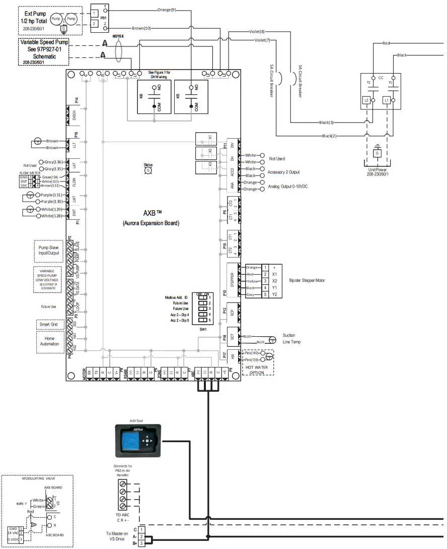
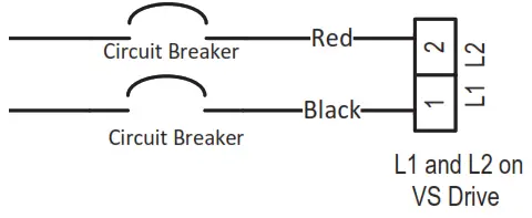
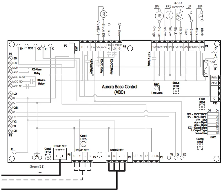
Compressor Section Wiring Schematics
Aurora Variable Speed Indoor Split
97P928-03A
Compressor Section Wiring Schematics cont.
Aurora Variable Speed Indoor Split
Notes
- Variable speed pump low voltage harness provided with Variable Speed Flow Center.
- Low voltage wiring CLASS 2.
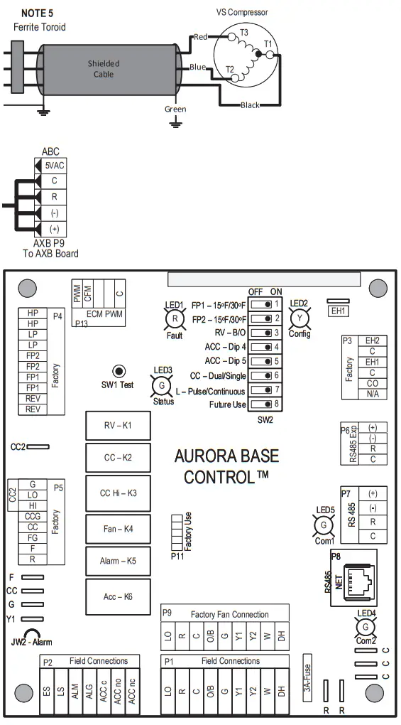
- Communication cable routed through Ferrite Toroid four times.
- Compressor power cable routed through Ferrite Toroid three times.
- Variable speed pump power wires to connect the pump to L1 and L2 on the AXB board are provided with Variable Speed Flow Center.
- Wiring harness supplied with valve.
Legend
| Factory Low voltage wiring | |
| Factory Line voltage wiring | |
| Field low voltage wiring | |
| Field line voltage wiring | |
| Optional block | |
| DC Voltage PCB traces | |
| Field Installed Item | |
| ● | Junction |
| ○ | Quick connect terminal |
| Wire nut | |
| Field wire lug | |
| Ground | |
| Relay Contacts- N.O., N.C. | |
| Fuse | |
| Color identification tape on wire. | |
| Thermistor | |
| Light emitting diode – Green | |
| Relay coil | |
| Capacitor w/ bleed resistor | |
| Switch – Condensate overflow | |
| Switch – High pressure | |
| Switch – Low pressure | |
| Current Transducer (CT) | |
| Polarized connector |
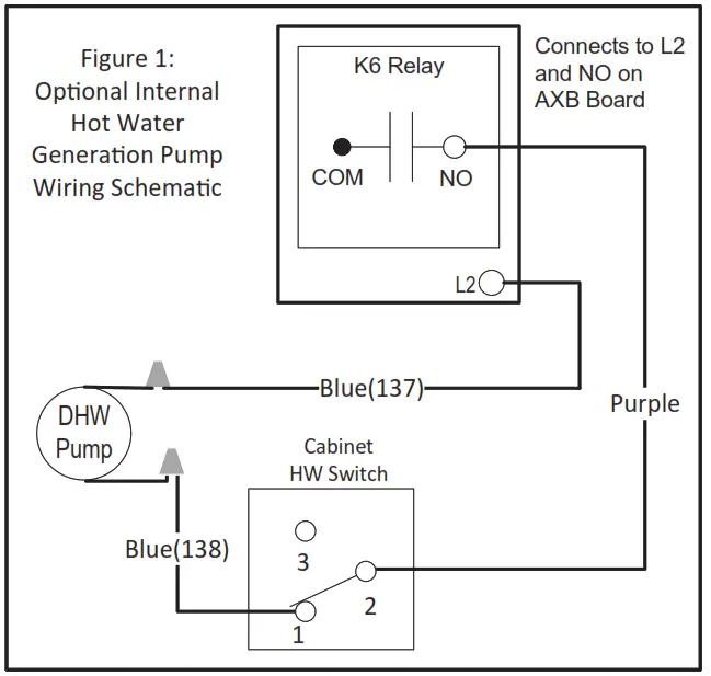
| CC – Compressor Contactor CO – Condensate overflow sensor K5 – DHW pump relay K6 – Loop pump relay CR3 – PSC Fan Speed Relay CR4 – PSC Fan Power Relay CS – Compressor Solenoid F1, F2 – Fuses HE – Heater element HP – High pressure switch LP – Low pressure switch ER1 to ER4 – Aux heat stage relays | PB1, PB2 – Power blocks PS – Power strip RV – Reversing Valve coil SW1 – DIP Switch – 5 position AXB SW1 – TEST MODE ABC Board SW2 – DIP Switch – 8 position ABC Board FP1, FP2 – Freeze Protection TS – Thermal limit switch SC – Start Contactor SR – Start Relay HWL – Hot water limit sensor WCL – Water Coil Limit Sensor |
 Compressor Section Wiring Schematics cont.
Aurora Variable Speed Indoor Split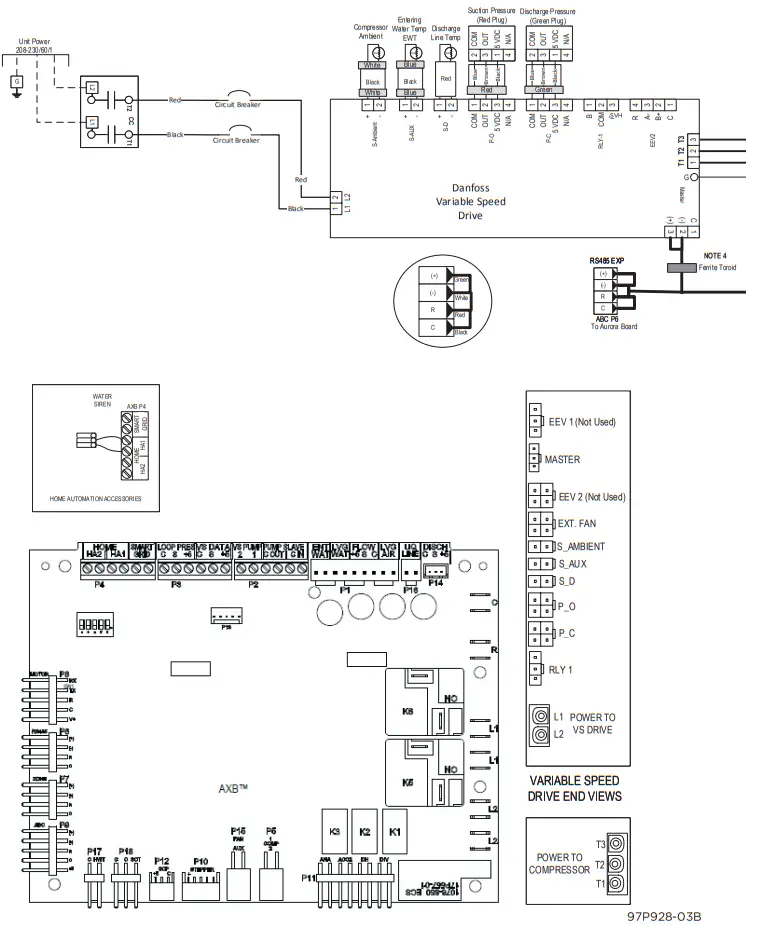 Compressor Section Wiring Schematics cont.
Aurora Variable Speed Indoor Split
| ABC SW2 Accessory Relay | ||
| DESCRIPTION | SW2-4 | SW2-5 |
| Cycle with Blower | ON | ON |
| Cycle with Compressor | OFF | OFF |
| Water Valve Slow Opening | ON | OFF |
| Cycle with Comm. T-stat Hum Cmd | OFF | ON |
| AXB Accessory 2 DIP Seƫngs | ||
| SW1-4 | SW1-5 | DESCRIPTION |
| ON | ON | Cycles with Blower |
| OFF | ON | Cycles with CC first stage compressor or compressor spd 1-12 |
| ON | OFF | Cycles with CC2 second stage of compressor or comp spd 7-12 |
| OFF | OFF | Cycles with DH from ABC board |
| Aurora LED Flash Codes | ||||
| Slow Flash | 1 second on and 1 second off | |||
| Fast Flash | 100 miilllliseconds on and 100 miilllliseconds off | |||
| Flash Code | 100 millliiseconds on and 400 miilllliiseconds off wiith a 2 second pause before repeating | |||
| Fault LED (LED 1, Red) | Random Start Delay (Alternating Colors) | |||
| Normal Mode | OFF | Status LED (LED1, Green) | Fast Flash | |
| Input Fault Lockout | Flash Code 1 | Configuration LED (LED 2, Yellow) | Fast Flash | |
| High Pressure Lockout | Flash Code 2 | Fault LED (LED 3, Red) | Fast Flash | |
| Low Pressure Lockout | Flash Code 3 | Configuration LED (LED 2, Yellow) | ||
| Freeze Protection- FP2 | Flash Code 4 | No Software Overide | OFF | |
| Freeze Protection – FP1 | Flash Code 5 | DIP Swiitch Overiide | Slow Flash | |
| Loss of Charge | Flash Code 6 | Status LED (LED 3, Green) | ||
| Condensate Overflow Lockout | Flash Code 7 | Normall Mode | ON | |
| Over/Under Volltage Shutdown | Flash Code 8 | Controll is Non – Functiional | OFF | |
| Future Use | Flash Code 9 | Test Mode | Slow Flash | |
| Lockout Actiive | Fast Flash | |||
| Fault- FP1 and FP2 Sensor Error | Flash Code 11 | Dehumidifiication Mode | Flash Code 2 | |
| Future Use | Flash Code 12 | Future Use | Flash Code 3 | |
| Non-Criticall AXB Sensor Error | Flash Code 13 | Future Use | Flash Code 4 | |
| Critical AXB Sensor Error | Flash Code 14 | Load Shed | Flash Code 5 | |
| Alarm – Hot Water | Flash Code 15 | ESD | Flash Code 6 | |
| Fault Variiable Speed Pump | Flash Code 16 | Future Use | Flash Code 7 | |
| Future Use | Flash Code 17 | Fault LED (LED 1, Red) Cont. | ||
| Non-Criitiicall Communication Error | Flash Code 18 | Safe Mode – Ambiient Temp Sensor | Flash Code 49 | |
| Fault – Critical Communication Error | Flash Code 19 | Fault – Diischarge Temperature Sensor | Flash Code 51 | |
| Allarm – Low Loop Pressure | Flash Code 21 | Fault – Suction Pressure Sensor | Flash Code 52 | |
| Fault – Communication ECM Fan Motor Error | Flash Code 22 | Faullt – Condensiing Pressure Sensor | Flash Code 53 | |
| Alarm – Home Automation 1 | Flash Code 23 | Fault – Low Supply Voltage | Flash Code 54 | |
| Allarm – Home Automation 2 | Flash Code 24 | Fault – Compressor Out of Envelope | Flash Code 55 | |
| Fault – EEV Error | Flash Code 25 | Fault – Over Current | Flash Code 56 | |
| Derate – Drive Temperature | Flash Code 41 | Fault – Over/Under Volltage | Flash Code 57 | |
| Derate – High Diischarge Temperature | Flash Code 42 | Fault – Hiigh Drive Temperature | Flash Code 58 | |
| Derate – Low Suction Temperature | Flash Code 43 | Fault – Drive Internal Error MOC/AOC | Flash Code 59 | |
| Derate – Low Condensing Pressure | Flash Code 44 | Fault – Multiiple Safe Modes | Flash Code 61 | |
| Derate – High Condensing Pressure | Flash Code 45 | EEV2 Fault – Loss of Charge | Flash Code 71 | |
| Derate – Outer Power Liimiit | Flash Code 46 | EEV2 Safe Mode – Suc Temp Sensor | Flash Code 72 | |
| Safe Mode – EEV (Indoor) Communication | Flash Code 47 | EEV2 Safe Mode – LAT Temp Sensor | Flash Code 73 | |
| Safe Mode – EEV (Outdoor) Communicatiion | Flash Code 48 | EEV2 Safe Mode – Max Op Pressure | Flash Code 74 | |
| EEV1 Fault – Loss of Charge | Flash Code 75 | |||
| EEV1Safe Mode – Suctiion Temp Sensor | Flash Code 76 | |||
| EEV1Safe Mode – LAT Temp Sensor | Flash Code 77 | |||
| EEV1 Safe Mode – Max Op Pressure | Flash Code 78 | |||
Compressor Section Wiring Schematics cont.
Aurora Variable Speed Indoor Split with UPC
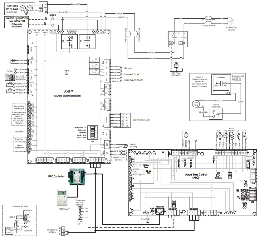
Compressor Section Wiring Schematics cont.
Aurora Variable Speed Indoor Split with UPC
Notes
- Variable speed pump low voltage harness provided with Variable Speed Flow Center.
- Low voltage wiring CLASS 2.
- Communication cable routed through Ferrite Toroid four times.
- Compressor power cable routed through Ferrite Toroid three times.
- Variable speed pump power wires to connect the pump to L1 and L2 on the AXB board are provided with Variable Speed Flow Center.
- Wiring harness supplied with valve.
| Factory Low voltage wiring | |
| Factory Line voltage wiring | |
| Field low voltage wiring | |
| Field line voltage wiring | |
| Optional block | |
| DC Voltage PCB traces | |
| Field Installed Item | |
| ● | Junction |
| ○ | Quick connect terminal |
| Wire nut | |
| Field wire lug | |
| Ground | |
| Relay Contacts- N.O., N.C. | |
| Fuse | |
| Color identification tape on wire. | |
| Thermistor | |
| Light emitting diode – Green | |
| Relay coil | |
| Capacitor w/ bleed resistor | |
| Switch – Condensate overflow | |
| Switch – High pressure | |
| Switch – Low pressure | |
| Current Transducer (CT) | |
| Polarized connector |
| CC – Compressor Contactor CO – Condensate overflow sensor K5 – DHW pump relay K6 – Loop pump relay CR3 – PSC Fan Speed Relay CR4 – PSC Fan Power Relay CS – Compressor Solenoid F1, F2 – Fuses HE – Heater element HP – High pressure switch LP – Low pressure switch ER1 to ER4 – Aux heat stage relays | PB1, PB2 – Power blocks PS – Power strip RV – Reversing Valve coil SW1 – DIP Switch – 5 position AXB SW1 – TEST MODE ABC Board SW2 – DIP Switch – 8 position ABC Board FP1, FP2 – Freeze Protection TS – Thermal limit switch SC – Start Contactor SR – Start Relay HWL – Hot water limit sensor WCL – Water Coil Limit Sensor |
Air Handler Wiring Schematics
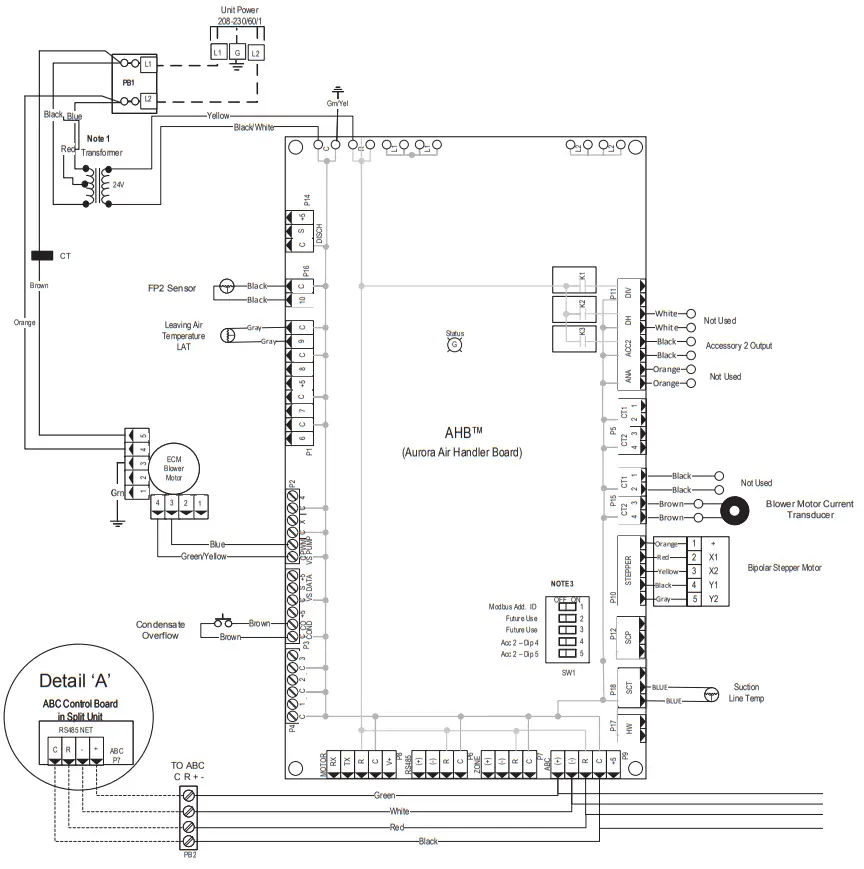
Air Handler Wiring Schematics cont.
| 7 SeriesAir Handler Air Flow | |||||||||||||
| Model | Max ESP | Speed 1 | Speed 2 | Speed 3 | Speed 4 | Speed 5 | Speed 6 | Speed 7 | Speed 8 | Speed 9 | Speed 10 | Speed 11 | Speed 12 |
| 033 | 0.75 | 250 | 400 G | 550 L | 650 | 750 | 850 | 1000 | 1150 | 1250 H | 1350 Aux | 1450 | 1600 |
| 042 | 0.75 | 250 | 450 G | 650 L | 800 | 950 | 1050 | 1200 | 1350 | 1450 | 1600 H | 1750 Aux | 1850 |
| 050 | 0.75 | 300 | 550 G | 800 L | 1000 | 1150 | 1300 | 1450 | 1600 | 1750 | 1900 H | 2050 Aux | 2200 |
| **VS Compressor Speed | 1-2 | 3-4 | 5-6 | 7-8 | 9-10 | 11-12 | |||||||
** VS Compressor speed is given for the factory default cfm se ngs. When the cfm default se ngs are changed it will change the rela onship to the compressor speed that is shown in the table. In cooling mode compressor speeds 10-12 are only available when SuperBoost mode is selected at the thermostat. Factory se ngs are at recommended G, L , H and Aux posi ons
“G” may be located anywhere within the air ow table.
“L” seng should be located within the boldface CFM range
“H” seng MUST be located within the shaded CFM range
“Aux” seng MUST be equal to or greater than “H” seng
CFM is controlled within 5% up to the maximum ESP
Communicating Thermostat will connect to the COMM STAT (C R + -)
power block PB3 in the air handler. A 4-conductor, 20AWG wire will need to connect from the TO ABC (C R + -) power block (PB2) in the Air Handler to the ABC P7(See detail ‘A’ on schematic) connection on the ABC board in the compressor section.
Communicating Thermostat
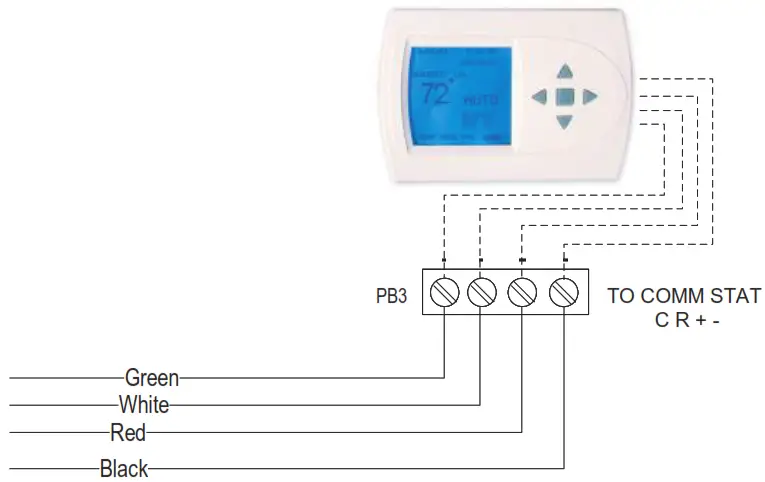
Note: On the AID Tool Configure Aurora Screen, confirm the AHB is added and communicating.
Notes
1 – To operate in 208V mode replace the blue transformer wire connected to PB1-L2 with red transformer wire.
2 – Low voltage wiring CLASS 2.
3 – DIP switch 1 on SW1 must be set in the OFF position.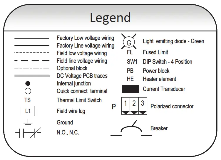 Air Handler Wiring Schematics cont.
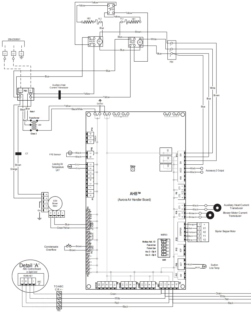
| 7 SeriesAir Handler Air Flow | |||||||||||||
| Model | Max ESP | Speed 1 | Speed 2 | Speed 3 | Speed 4 | Speed 5 | Speed 6 | Speed 7 | Speed 8 | Speed 9 | Speed 10 | Speed 11 | Speed 12 |
| 033 | 0.75 | 250 | 400 G | 550 L | 650 | 750 | 850 | 1000 | 1150 | 1250 H | 1350 Aux | 1450 | 1600 |
| 042 | 0.75 | 250 | 450 G | 650 L | 800 | 950 | 1050 | 1200 | 1350 | 1450 | 1600 H | 1750 Aux | 1850 |
| 050 | 0.75 | 300 | 550 G | 800 L | 1000 | 1150 | 1300 | 1450 | 1600 | 1750 | 1900 H | 2050 Aux | 2200 |
| **VS Compressor Speed | 1-2 | 3-4 | 5-6 | 7-8 | 9-10 | 11-12 | |||||||
11/29/2018
** VS Compressor speed is given for the factory default cfm sengs. When the cfm default sengs are changed it will change the relaonship to the compressor speed that is shown in the table. Incooling mode compressor speeds 10-12 are only available when SuperBoost mode is selected at the thermostat. Factory sengs are at recommended G, L , H and Aux posions
“G” may be located anywhere within the airow table.
“L” seng should be located within the boldface CFM range
“H” seng MUST be located within the shaded CFM range
“Aux” seng MUST be equal to or greater than
“H” seng CFM is controlled within 5% up to the maximum ESP
Communicating Thermostat will connect to the COMM STAT (C R + -) power block PB3 in the air handler. A 4-conductor, 20AWG wire will need to connect from the TO ABC (C R + -) power block (PB2) in the Air Handler to the ABC P7(See detail ‘A’ on schematic) connection on the ABC board in the compressor section.
Communicating Thermostat
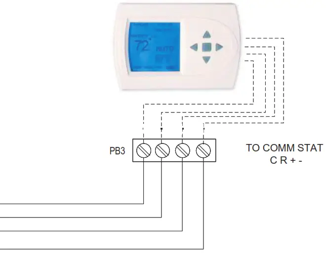
Note: On the AID Tool Configure Aurora Screen, confirm the AHB is added and communicating.
Notes
1 – To operate in 208V mode replace the blue transformer wire connected to PB1-L2 with red transformer wire.
2 – Low voltage wiring CLASS 2.
3 – DIP switch 1 on SW1 must be set in the OFF position.Dual Power Supply Connections
If two separate circuits are used to supply power to the auxiliary heat kit, the Installer will need to verify that each leg of the auxiliary heat circuit breakers are wired from the power supply correctly in order for the electric heat kit to operate properly. This can be done by measuring the supply side voltage of the auxiliary heat circuit breakers. Put a voltmeter on the L2 side of Circuit Breaker One and on the L2 side of Circuit Breaker Two. The voltmeter should read approximately 0 volts. If the meter reads high voltage, the auxiliary heat breakers need to be rewired so that breakers in the auxiliary heat kit match the wiring of the Disconnect Panel breakers. Meaning, L1 and L2 from one breaker in the disconnect panel must L1 and L2 from one breaker in the disconnect panel must connect to L1 and L2 at one of the auxiliary heat circuit breakers and L1 and L2 from the other breaker in the disconnect panel must connect to L1 and L2 of the other auxiliary heat circuit breaker, making sure that the L1 and L2 from each disconnect breaker matches the L1 and L2 at each of the auxiliary heat breakers.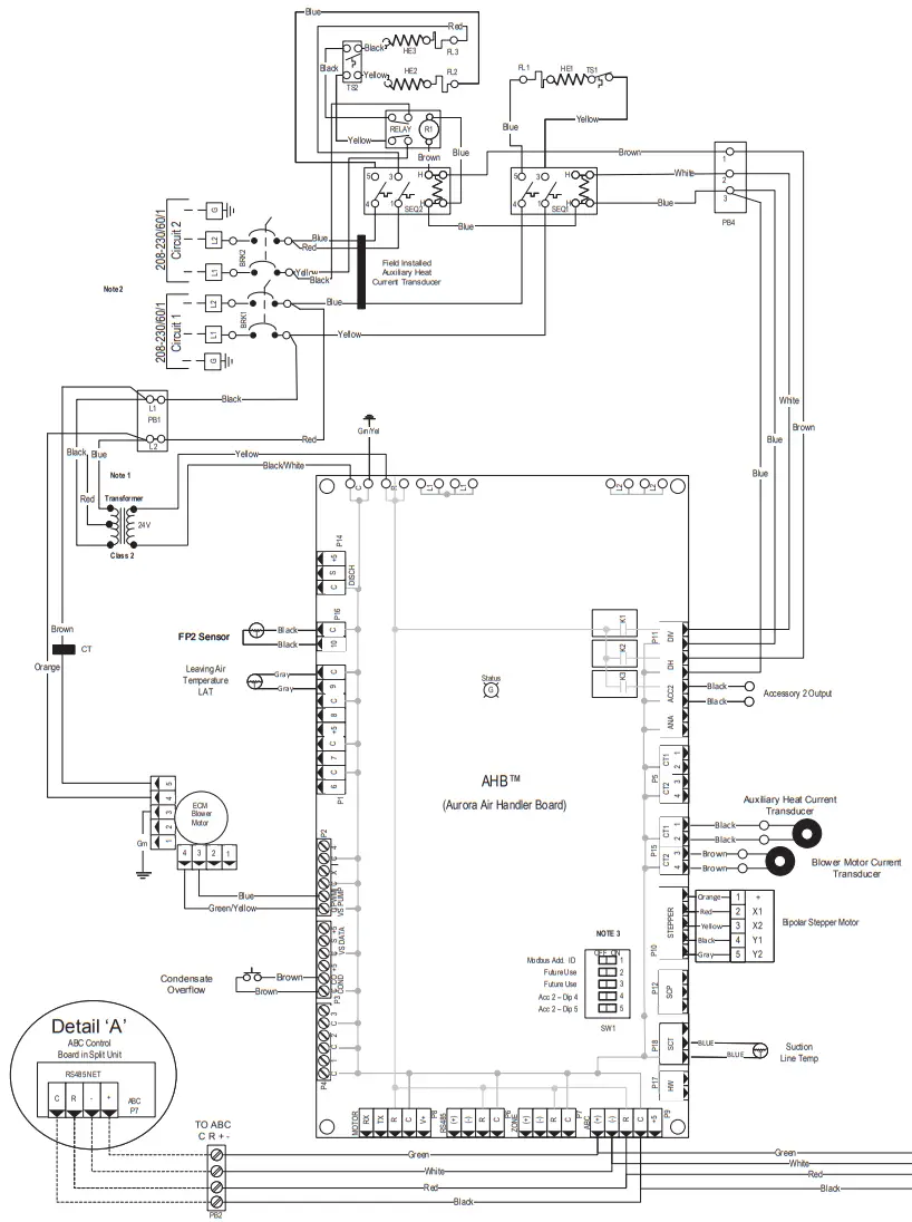
| 7 SeriesAir Handler Air Flow | |||||||||||||
| Model | Max ESP | Speed 1 | Speed 2 | Speed 3 | Speed 4 | Speed 5 | Speed 6 | Speed 7 | Speed 8 | Speed 9 | Speed 10 | Speed 11 | Speed 12 |
| 033 | 0.75 | 250 | 400 G | 550 L | 650 | 750 | 850 | 1000 | 1150 | 1250 H | 1350 Aux | 1450 | 1600 |
| 042 | 0.75 | 250 | 450 G | 650 L | 800 | 950 | 1050 | 1200 | 1350 | 1450 | 1600 H | 1750 Aux | 1850 |
| 050 | 0.75 | 300 | 550 G | 800 L | 1000 | 1150 | 1300 | 1450 | 1600 | 1750 | 1900 H | 2050 Aux | 2200 |
| **VS Compressor Speed | 1-2 | 3-4 | 5-6 | 7-8 | 9-10 | 11-12 | |||||||
11/29/2018
** VS Compressor speed is given for the factory default cfm sengs. When the cfm default se ngs are changed it will change the rela onship to the compressor speed that is shown in the table. In cooling mode compressor speeds 10-12 are only available when SuperBoost mode is selected at the thermostat. Factory sengs are at recommended G, L , H and Aux posi ons
“G” may be located anywhere within the air ow table.
“L” seng should be located within the boldface CFM range
“H” seng MUST be located within the shaded CFM range
“Aux” seng MUST be equal to or greater than
“H” seng CFM is controlled within 5% up to the maximum ESP
Dual Power Supply Connections
If two separate circuits are used to supply power to the auxiliary heat kit, the Installer will need to verify that each leg of the auxiliary heat circuit breakers are wired from the power supply correctly in order for the electric heat kit to operate properly. This can be done by measuring the supply side voltage of the auxiliary heat circuit breakers. Put a voltmeter on the L2 side of Circuit Breaker One and on the L2 side of Circuit Breaker Two. The voltmeter should read approximately 0 volts. If the meter reads high voltage, the auxiliary heat breakers need to be rewired so that breakers in the auxiliary heat kit match the wiring of the Disconnect Panel breakers. Meaning, Ll and L2 from one breaker in the disconnect panel must connect to 1:1 and L2 at one of the auxiliary heat circuit breakers and Ll and L2 from the other breaker in the disconnect panel must connect to 1:1 and L2 of the other auxiliary heat circuit breaker, making sure that the Ll and L2 from each disconnect breaker matches the 12I and L2 at each of the auxiliary heat breakers.
Communicating Thermostat will connect to the COMM STAT (C R + -) power block PB3 in the air handler. A 4-conductor, 20AWG wire will need to connect from the TO ABC (C R + -) power block (PB2) in the Air Handler to the ABC P7(See detail ‘A’ on schematic) connection on the ABC board in the compressor section.
Communicating Thermostat
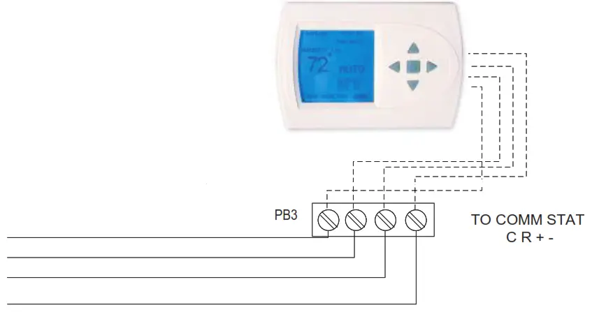
Note: On the AID Tool Configure Aurora Screen, confirm the AHB is added and communicating.
Notes
1 – To operate in 208V mode replace the blue transformer wire connected to PB1-L2 with red transformer wire.
2 – Use manufacturer’s part number 19P592-01 (jumper bar assembly) when single source power is required.
3 – DIP switch 1 on SW1 must be set in the OFF position.
4- Low voltage wiring CLASS 2Air Handler Wiring Schematics cont.
Variable Speed Pump (UPMXL 25-124)
Variable Speed Flow Center With
1 – UPMXL 25-124 Pump
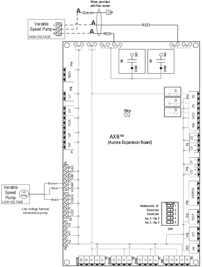
Variable Speed Flow Center With 2 – UPMXL 25-124 Pumps
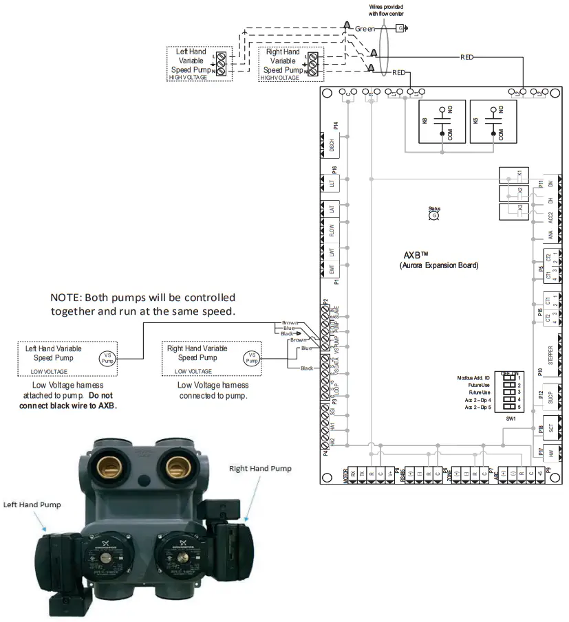
Compressor Section Wiring Schematics cont.
Aurora UPC
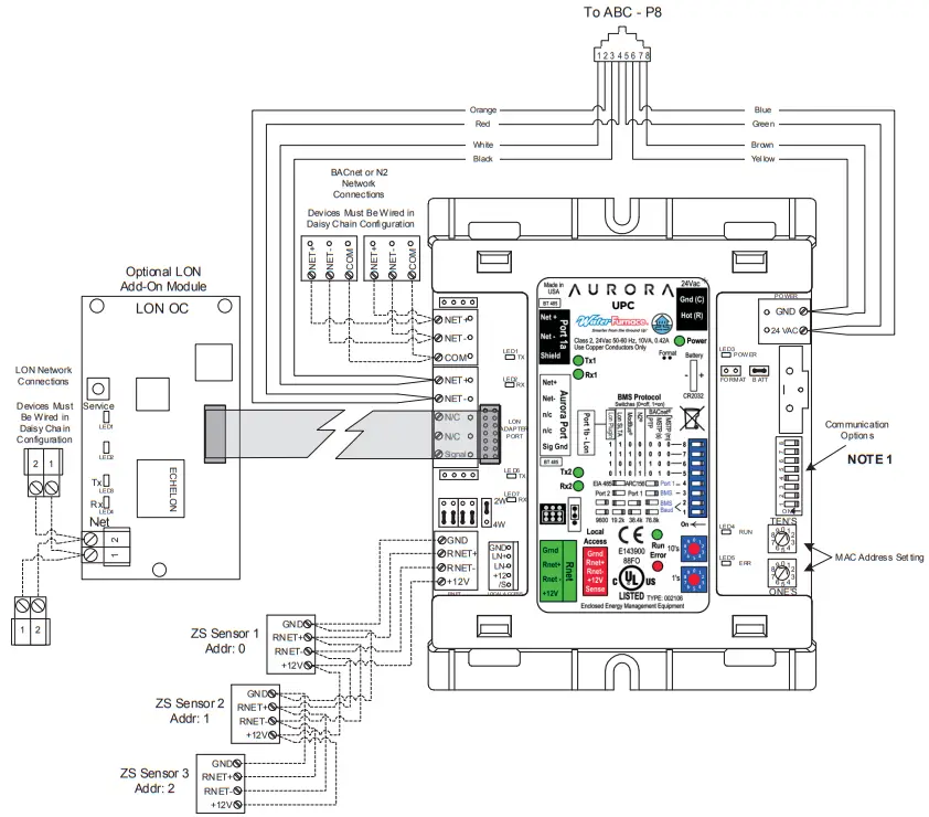
ZS Sensor Information
Zone Sensors can be wired in daisy chain as show or in a star or hybrid configuration. Maximum of 5 sensors per UPC. Maximum allowable load 210mA. See the UPC install manual for possible sensor combinations.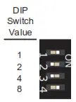 Each ZS sensor must have a unique address, but the addresses do not need to be sequential. Use the DIP switches on the back of the ZS sensor to set an address from 0 to 4. (0 is the factory default.) Each DIP switch has the value shown in the figure to the left. Turn on as many DIP switches as you need so that their total value equals the address.
Notes
1. Use DIP Switches 5 – 8 to change communication protocol and DIP switches 1 – 2 to change BACnet baud rate
Legend
 Fact ory Lo w Vo lt age Wiring
Field Low V olta ge Wiring
RJ45 Connector
Engineering Guide Specifications
General
Furnish and install WaterFurnace Water Source Heat Pumps, as indicated on the plans. Equipment shall be completely assembled, piped and internally wired. Capacities and characteristics as listed in the schedule and the specifications that follow. The reverse cycle heating/cooling units shall be either suspended type with horizontal air inlet and discharge or floor mounted type with horizontal air inlet and vertical upflow, or downflow air discharge. Units shall be AHRI/ISO 13256-1 certified and listed by a nationally recognized safety-testing laboratory or agency, such as ETL Testing Laboratory. Each unit shall be computer runtested at the factory with conditioned water and operation verified to catalog data. Each unit shall be mounted on a pallet and shipped in a corrugated box or stretch-wrapped. The units shall be designed to operate with entering liquid temperature between 20°F and 120°F [-6.7°C and 48.9°C].
Casing and Cabinet
The cabinet shall be fabricated from heavy-gauge galvanized steel and finished with corrosion-resistant powder coating. This corrosion protection system shall meet the stringent 1000 hour salt spray test per ASTM B117. The interior shall be insulated with 1/2-inch thick, multi-density, cleanable aluminum foil coated glass fiber with edges sealed or tucked under flanges to prevent the introduction of glass fibers into the discharge air. Standard cabinet panel insulation must meet NFPA 90A requirements, air erosion and mold growth limits of UL- 181, stringent fungal resistance test per ASTM-C1071 and ASTM G21, and shall meet zero level bacteria growth per ASTM G22. Unit insulation must meet these stringent requirements or unit(s) will not be accepted.
Three compressor compartment access panels shall be ‘liftout’ removable. The front access panel shall be lift-out to provide easy access to the electrical/compressor section. The control box shall be hinged and removable to allow easy access to the compressor. The internal component layout shall provide for service access from the front side for restricted installations.
The air handler shall be provided with two large access panels and shall be removable with supply and return ductwork in place. The internal components layout shall provide for major service with the unit in-place for restricted access installations. The blower assembly access shall be slide-out serviceable via a ‘works-in-a-drawer’ design. The cabinet shall be convertible to horizontal or downfl ow applications by reconfi guring the cabinet using only a nut driver. The unit shall be ‘zero clearance’ approved on any of its external surfaces. A duct collar shall be provided for fi eld installation on the supply air opening. The air handler shall be supplied with an integral return air fi lter rack (air fi lter is fi eld supplied).
Refrigerant Circuit
All units shall contain a sealed refrigerant circuit including a hermetic motor-compressor, oil seperator, electronic expansion valve, reversing valve, coaxial tube water-torefrigerant heat exchanger, optional hot water generator coil, and service ports. Compressors shall be high-efficiency variable speed scroll type designed for heat pump duty and mounted on double vibration isolators. Compressor motors shall be permanent magnet type. All air handlers shall provide an electronic expansion valve, enhanced fi n and tube air-to-refrigerant heat exchanger of the “A” coil design. The fi nned tube coil shall be sized for low-face velocity and constructed of lanced aluminum fi ns bonded to aluminum tubes in a staggered pattern. The coil shall include a composite drain pan.
Both electronic expansion valves shall provide proper superheat over the entire liquid temperature range with minimal “hunting.”
Refrigerant to air heat exchangers shall utilize aluminum tube construction rated to withstand 600 psig (4135 kPa) refrigerant working pressure. Refrigerant to water heat exchangers shall be of copper (cupronickel optional) inner water tube and steel refrigerant outer tube design, rated to withstand 600 psig (4135 kPa) working refrigerant pressure and 450 psig (3101 kPa) working water pressure.
All units shall have the source coaxial tube refrigerant-to water heat exchanger and the optional hot water generator coil coated with ThermaShield insulation. Refrigerant suction lines shall be insulated to prevent condensation at low liquid temperatures.
Blower Motor and Assembly
The blower shall be an oversized direct drive centrifugal type with a dynamically balanced wheel. The housing and wheel shall be designed for quiet low outlet velocity operation and of galvanized or galvalume steel construction. Tight blower housing geometry shall not be permitted. The blower housing shall be removable from the cabinet without disconnecting the supply air ductwork for servicing of the blower motor through a ‘works-in-a-drawer’ design. The high effi ciency blower motor shall be a variable speed ECM type. The blower motor shall be isolated from the housing by rubber grommets. The motor shall be perma- nently lubricated ball bearings and have thermal overload protection.
Electrical
A control box shall be located within the compressor and air handler compartments (air handler shall contain a 100VA transformer) and the compressor compartment shall contain a 24 Volt activated, 2 pole compressor contactor, circuit breakers for protecting loop pumps and compressor drive, removable terminal block for thermostat wiring, variable speed compressor drive and solid-state controller for complete unit operation. Electromechanical operation WILL NOT be accepted. Units shall be name-plated for use with time delay fuses or HACR circuit breakers. Unit controls shall be communicating type and provide heating or cooling as required by the remote thermostat/sensor. An Aurora Advanced VS Control, a microprocessor based controller, interfaces with a digital communicating thermostat to monitor and control unit operation shall be provided. The control shall provide operational sequencing, blower speed
Engineering Guide Specifi cations cont.
control, blower failure, high and low pressure switch monitoring, freeze detection, hot water limit thermistor sensing, condensate overfl ow sensing, auxiliary heat staging, lockout mode control, hot water and loop pump control, LED status and fault indicators, fault memory, fi eld selectable options, compressor envelope management, energy consumption measurement, and accessory output. The fault signals shall be plain English text and displayed on the thermostat. The Aurora Advanced VS Control shall also feature an On Peak input signal for utility controlled demand programs, intelligent hot water generation with user adjustable temperature limit, loop pump linking for multiple units driving a common fl ow center and up to two optional home automation inputs to drive dedicated alarms for sump pump, security system, and smoke/CO2 or dirty air fi lter sensors. As standard, the energy, performance and refrigerant monitoring kits will provide real time data including total power consumption, entering and leaving water temperature, fl owrate and heat of extraction/rejection capacity data, refrigerant superheat and subcooling. The capability for communicating to advanced zoning packages with up to six zones shall also be provided with complete fault and information display on the zoning MasterStat.
A detachable terminal block with screw terminals will be provided for field control wiring. All units shall have knockouts for entrance of low and line voltage wiring. The blower motor and control box shall be harness plug wired for easy removal.
The air handler shall contain integral circuit breakers on all units employing 15 kW or 20 kW electric heat. The 100VA transformer shall be protected by internal circuit breaker.
An Aurora Interface Diagnostic (AID) Tool shall communicate with the Aurora control allowing quick and easy access to setup, monitoring, and troubleshooting of any Aurora control. The device shall include the features of ECM airflow setup, VS pump and modulating water valve setup, fault description and history, manual operation capability, sensor readings, timings, and other diagnostic tools.
Option: An Aurora Unitary Protocol Converter (UPC) shall be included that communicates directly with the Aurora Heat Pump Control and allows access/control of a variety of internal Aurora heat pump operations such as sensors, relay operation, faults and other information. In turn, the UPC shall convert the internal Aurora Modbus protocol to BACnet MS/TP protocol for communication over a HAS system. Additional individual unit configuration items such as ECM fan speeds or freeze detection settings shall be directly available over the HAS without the need for access to the actual heat pump.
Piping
Supply and return water connections shall be 1 in. [25.4 mm] FPT brass swivel fittings, which provide a union and eliminate the need for pipe wrenches and sealants when making field connections. The optional hot water generator shall have sweat type connections. All source water piping shall be insulated to prevent condensation at low liquid temperatures. Refrigeration connections shall be made using sweat copper joints. The air handler condensate connections shall be a 3/4 in. NPT.
Options and Accessories
Cupronickel Heat Exchanger
An optional cupronickel water-to-refrigerant heat exchanger shall be provided.
Hot Water Generator
An optional ThermaShield coated heat reclaiming hot water generator coil of vented double-wall copper construction suitable for potable water shall be provided. The coil and hot water circulating pump shall be factory mounted inside the unit with integral electronic high limit temperature monitoring and external on/off switch. Hot water set point is selectable through the AID Tool.
Thermostat (field-installed)
A communicating auto-changeover electronic digital thermostat shall be provided. The thermostat shall offer variable speed heating and cooling staging with precise temperature control. An OFF-HEAT-AUTO-COOL-EMERG system switch, OFF-AUTO-INTERMITTENT blower switch, and indicating display shall be provided. The thermostat shall display in °F or °C. The thermostat shall provide real time energy consumption data of the unit.
Color Touchscreen Thermostat (field-installed)
A color touchscreen communicating auto-changeover electronic digital thermostat shall be provided. The thermostat shall offer variable speed heating and cooling staging with precise temperature control. An OFF-HEAT-AUTOCOOL-EMERG system switch, OFF-AUTO-INTERMITTENT blower switch, and indicating display shall be provided. The thermostat shall display in °F or °C. The thermostat shall provide real time and historical energy consumption data of the unit.
Earth Loop Flow Center (field-installed)
A self-contained module shall provide all liquid flow, fill and connection requirements for ground source closed loop systems up to 20 gpm. The pumps shall be wired to a power block located in the nearest unit. The heat pump units shall contain low voltage pump linking control so that two units may share one flow center.
Revision Guide
| Pages: | Description: | Date: | By: |
| Misc. | Remove EEV, new part number revision | — | JM |
| 10 | Updated line set length | 12-Dec-20 | MA |
| All | Document created | 26-Feb-20 | MA |
WaterFurnace works continually to improve its products. As a result, the design and specifications of each product at the time of order may be changed without notice. Please contact WaterFurnace at 1-888-929-2837 for latest design and specifications. Purchaser’s approval of this data set signifi es that the equipment is acceptable under the provisions of the job specification. Statements and other information contained herein are not express warranties and do not form the basis of any bargain between the parties, but are merely WaterFurnace’s opinion or commendation of its products. The latest version of this document is available at www.waterfurnace.com.
SD2703SNA 01/23![]()


