![]() UH8-RF V2 Zone Wiring Centre
UH8-RF V2 Zone Wiring Centre
Installation Guide Model: UH8-RF V2
UH8-RF V2 Zone Wiring Centre
![]() UH8-RF V2 Installation Manual
UH8-RF V2 Installation Manual
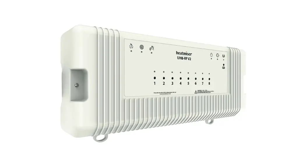
Description
The UH8-RF V2 is an 8 Zone central wiring centre for use with Heatmiser RF thermostats.
The UH8-RF V2 can be used to control any actuator or valve, which requires a 230v AC signal to open. For mid position valves and those requiring a closing signal, a changeover relay is required. The UH8-RF V2 also offers the ability to operate a boiler or other heat source through a volt free output with changeover contacts, giving you both a heat on signal and a heat off signal.
Additional outputs designed for use with hot water or underfloor heating systems, are also included as standard. These are the pump and valve outputs which would normally operate a manifold pump or a manifold valve.
Any output which is not needed can be ignored.
When wiring directly to the heat source is not possible, a radio link is provided to remotely enable a separate receiver, the RF-Switch.
Test switches are included for the installation engineer and further options include creepage protection and pump delay.
Operation
Using the toggle switches, each channel used on this system can be configured for either a radiator zone or underfloor heating zone.
When the thermostat sends a signal for heating, the UH8-RF V2 will provide a 230v AC output on the paired zone and also bring on the boiler/other heat source output. At the same time the UH8-RF V2 can send a radio signal to the RF-Switch. If the zone is configured as an underfloor heating zone, the UH8-RF V2 will also start the pump and valve outputs.
If an enable signal is received from a hot water time clock on the system, only the H/W output will become active. This is a timed output, which is normally fed to a cylinder thermostat, then to a valve, but could also be used for towel rails. In either case the valve auxiliary switch would operate the boiler/other heat source.
Other functions
Creepage
During hot weather the heating is not normally needed as often, this means that valves and pumps that are not being used can seize and refuse to operate. To prevent this, it is good practice to operate the valve or pump once a day, the creepage function does this for you.
Once enabled the UH8-RF V2 will operate each valve or pump for 1 minute, if the outputs have not been operated by a thermostat, within the preceding 24 hours. This function does not operate the boiler output.
Pump Delay
Some valves or actuators can take more than a minute to open, if the boiler and pump operate before the valve is open it can force a boiler to go to lockout and stop operating. This function delays the operation of the pump and boiler to give the actuators and valves time to open.
 Installation
The UH8-RF V2 can be mounted directly to a wall using four screws or alternatively, the unit can be DIN rail mounted.
When DIN Rail mounting, you first need to insert the two clips provided on the back of the UH8-RF V2, as shown in the image;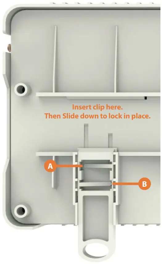
- On the back of the UH8-RF V2, position the clip in the middle and slide down.
- Points A and B locate in the corresponding holes and lock into place.
- Locate the UH8-RF V2 onto the DIN rail from the top.
- Pull the clip down and push the bottom of the UH8-RF V2 onto the DIN rail.
- Releasing the clip will lock the UH8-RF V2 in place on the DIN rail.
To remove the UH8-RF V2, pull both clips down and remove from the DIN rail.![]() UH8-RF V2 Wiring
UH8-RF V2 Wiring
The UH8-RF V2 should be fitted as close as possible to the equipment it is controlling, but never within a metal enclosure, if this cannot be avoided an extension antenna (EA1) must be fitted and placed outside the metal enclosure.
Connections
Mains Supply
Power supply into the UH8-RF V2 which should be fused at 5 amps these connections are marked;
L = live or phase 230v AC 50/60Hz
N = Neutral
E = Earth
Heat/Cool Enable
This is the main call for heat for the system, there are 3 connections;
C = common
NO = normally open
NC = normally closed
Electrically this is a two-way switch, whatever supply is placed on the C connection, is fed to the NC connection when there is no call for heat. This is then switched to the NO connection when there is a call for heat.
Most systems will use the common (C ) and normally open (NO) connections.
Hot Water
This output is used to control a hot water cylinder thermostat
C = common
NO = normally open
NC = normally closed
Electrically this is a two-way switch, whatever supply is placed on the common connection, is fed to the NC connection when there is no call for hot water. This is then switched to the NO connection when there is a call for hot water.
Hot Water Continued
Normally the NO connection would be wired to the hot water cylinder thermostat, then from there to the hot water valve, the valve auxiliary switch will then start the boiler/other heat source.
Most systems will use the common and normally open connections.
Zones 1…8
Zones outputs are clearly marked
L = live out to actuator or valve
N = neutral to actuator or valve
There are two connections live (L) and neutral (N), both terminals marked L are the same and both terminals marked N are the same.
Each zone output is numbered, Zone 1 will respond to radio signals from the thermostat paired to Zone 1. Zone 2 output will respond to thermostat numbered 2 etc.
Manifold Pump/Valve
Used for an underfloor heating manifold pump and or valve.
Connections are clearly marked
L = Live
E = Earth
N = Neutral
When an under-floor heating zone sends a call for heat to the UH8-RF V2, the live & neutral output will supply 230v to the manifold pump/valve. It is recommended that this is fed through a high limit switch, placed on the heating manifold to protect against mechanical failure of the manifolds temperature control.
Dew Point Sensor (Cooling Mode Only)![]()
Dew Point sensing help to reduce the risk of condensation whilst cooling is in demand.
When activated, the sensor sends a signal back to the UH8-RF V2, and will shutdown cooling to the manifold.
During this time, the dew point indicator light will show.
Connections (24 Volt DC)
+ = Positive
– = Negative
SL = Input
Engineers test switches
These are a block of 12 dip switches, used to test each zone, boiler, pump and HW outputs. To enable any output, put the switch in the ON position. When installation is complete all switches MUST be in the OFF position.
Record the rooms names connected to each zone with the zone number and record the channel number you have selected, you will need this information when installing the thermostats.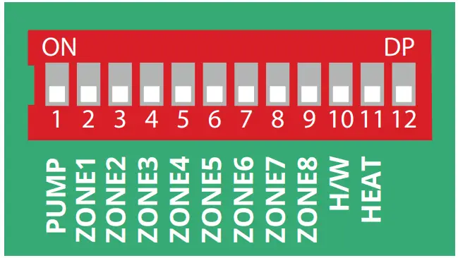
Fuses
5amp, 20mm anti-surge fuse, this fuse supplies power to all 230v outputs from the board, it protects the zone, pump and valve outputs.
Zones 1 to 8 Buttons and indicators
Each Zone has an indicator light and button associated with it.
Light functions:
- Light on when the zone output is on.
- Light flashes when the zone is in pairing mode.
Button functions:
- Single press to manually turn output On/Off.
- Hold down for 5 seconds to start pairing mode, (Indicator steady flash.)
- Hold down for 15 seconds to delete pairing, (indicator rapid flash).
System indicators When lights are on:
- Dew Point – Informs you that cooling has been shut off to prevent condensation.

- Hot Water- Output is On.

- Pump Output is On.

- System is cooling.

- System is heating.

- Flashes continous in pairing mode (RF Switch Pairing). Intermittent flashing to indicate communication.
![]() Wiring Diagram UH8-RF Direct Pump Connection
Wiring Diagram UH8-RF Direct Pump Connection
Wiring Key
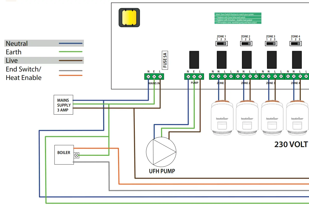 Front Panel Connection
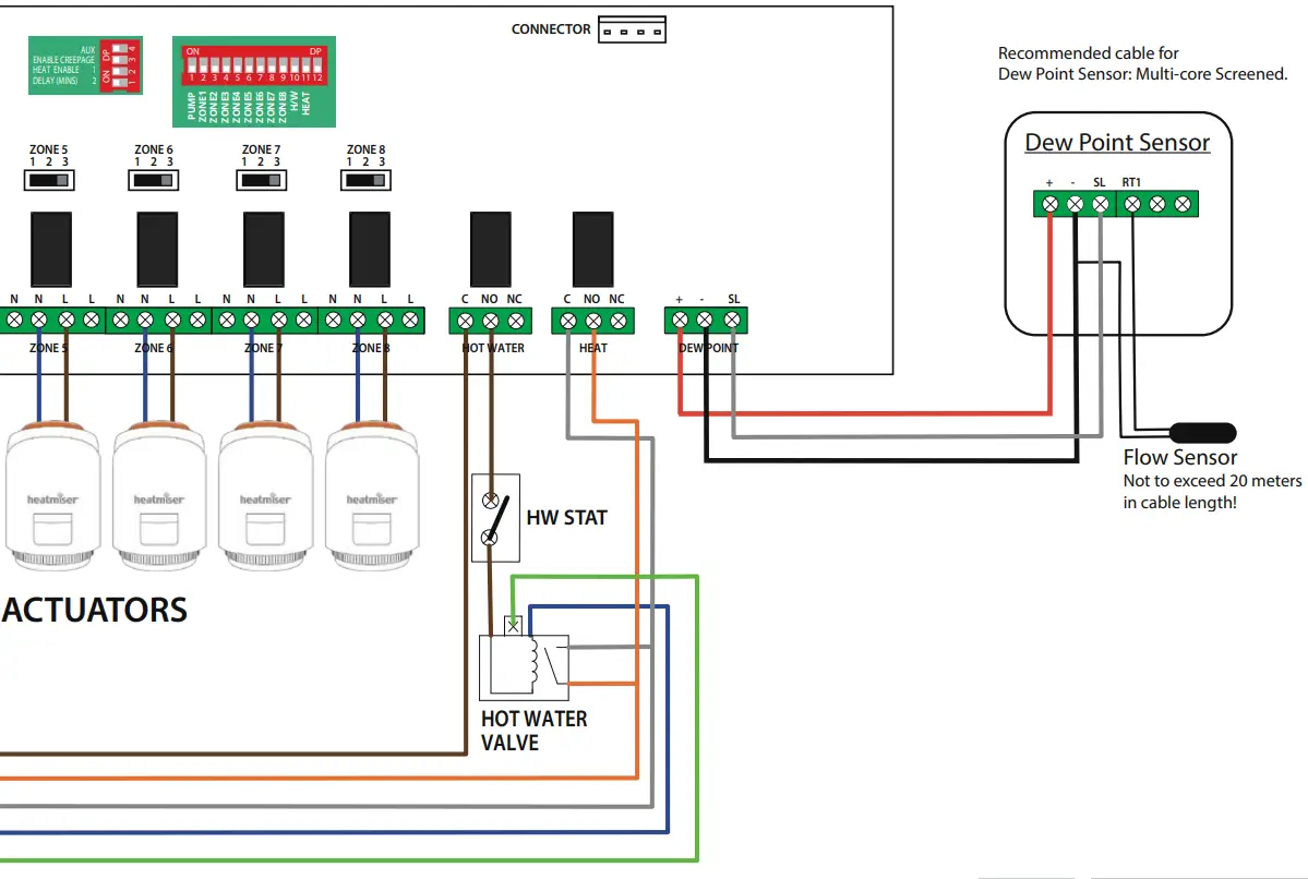 Ratings
| Supply | 230v AC 50Hz |
| Power consumption | 7W |
| Max load on boiler output | 3A 230v AC resistive. |
| Max load on H/W output | 3A 230v AC resistive. |
| Max load for zone outputs | 3A 230v AC resistive. |
| Max Total load | 5 Amps |
Optional Accessories
| RF-Switch | (Remote Boiler enable) |
| Boost | (Repeater) |
| neoPlug | (Repeater) |
| Extension Antenna (included) | (EA1) |
![]() Wiring Diagram UH8-RF with UFH & Radiator Valves
Wiring Diagram UH8-RF with UFH & Radiator Valves
Wiring Key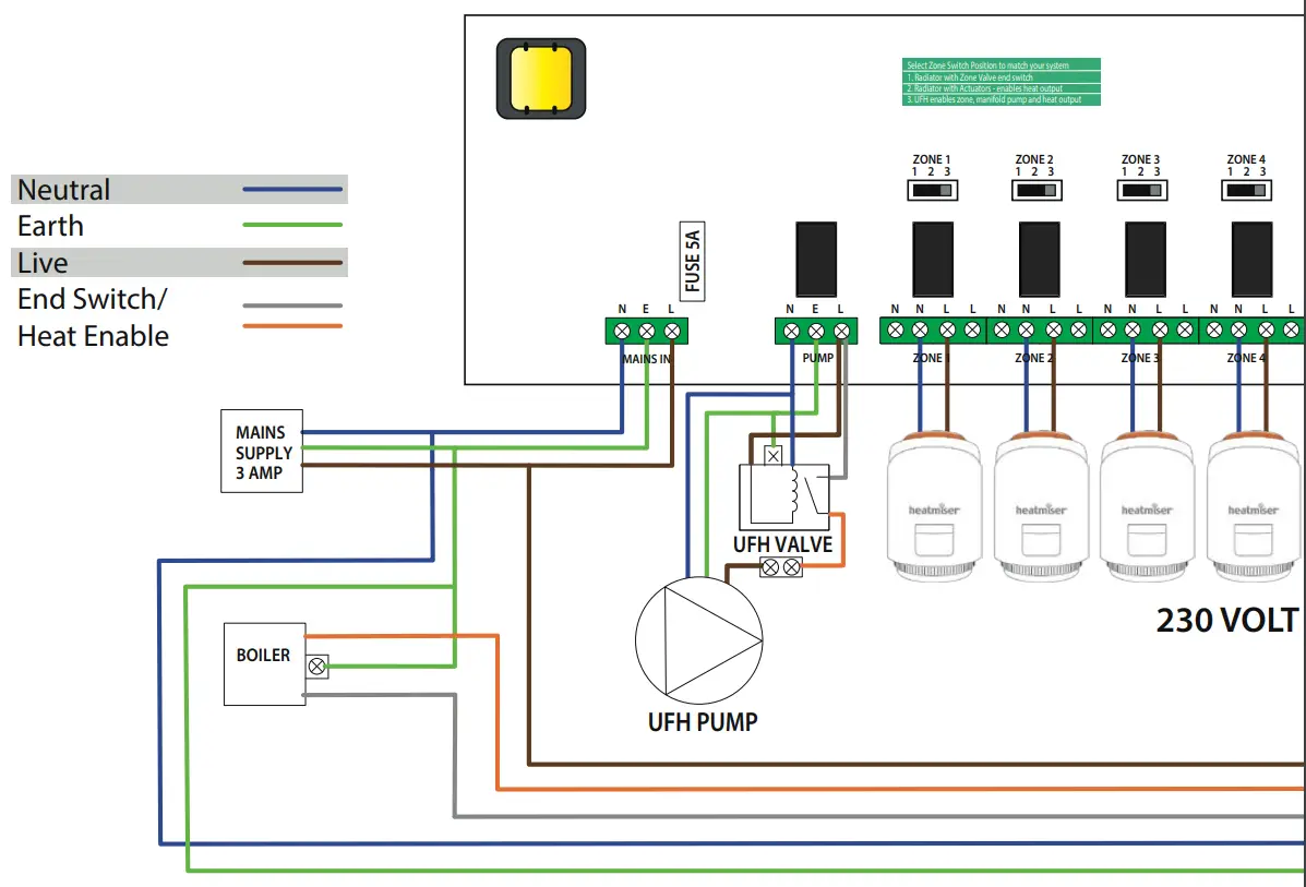 Front Panel Connection
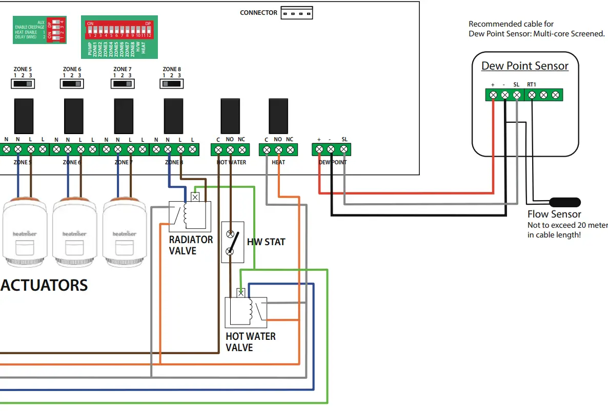 Ratings
| Supply | 230v AC 50Hz |
| Power consumption | 7W |
| Max load on boiler output | 3A 230v AC resistive. |
| Max load on H/W output | 3A 230v AC resistive. |
| Max load for zone outputs | 3A 230v AC resistive. |
| Max Total load | (EA1) |
System Setup
Zone Type Toggle Switches
There is a 3 position toggle switch above each zone. This switch allows 3 different switched outputs when the thermostat demands heat.
Position 1 – Zone output only.
When a thermostat is in demand, the UH8-RF will activate the Zone output to actuators only, PUMP and HEAT outputs will remain off.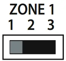
Position 2 – Zone output with heat demand.
When a thermostat is in demand the UH8-RF will activate the zone output to the actuators and heat demand to the boiler.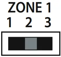 Position 3 – Zone output with heat demand and manifold pump.
When a thermostat is in demand, the UH8-RF will activate the zone output to the actuators, the heat demand to the boiler and the manifold pump.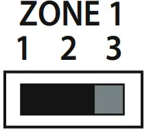 Pairing the UH8-RF V2 to the RF-Switch
· On the RF-Switch, press and hold the CH1 pairing button for 5 seconds.
The CH1 status LED will start to flash.
· Press and release the pairing button on the UH8-RF………….![]()
When the RF-Switch detects the pairing signal from the UH8-RF, the CH1 LED will stop flashing.
DIP Switches
There is a 4 way dip switch responsible for 3 functions;
- Demand RF Test
- Enable Creepage
- Heat Enable Delay 1 minute.
- Heat Enable Delay 2 minutes.
Innormal use these DIP switches can be ignored and should be left in the off position.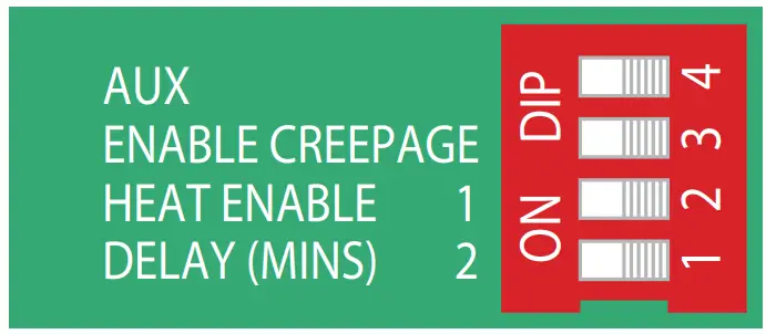 Heat Enable Delay, Dip Switches 1 & 2
Switch 2 ON, Switch 1 OFF = Will delay the heat output for 1 minute.
Switch 2 OFF, Switch 1 ON = Will delay the heat output for 2 minutes.
Switch 2 ON, Switch 1 ON = Will delay the heat output for 3 minutes.
Creepage Protection, Dip Switch 3
To enable creepage protection, put switch 3 to the ON position
 System Configuration
Zone Type Under-Floor Radiator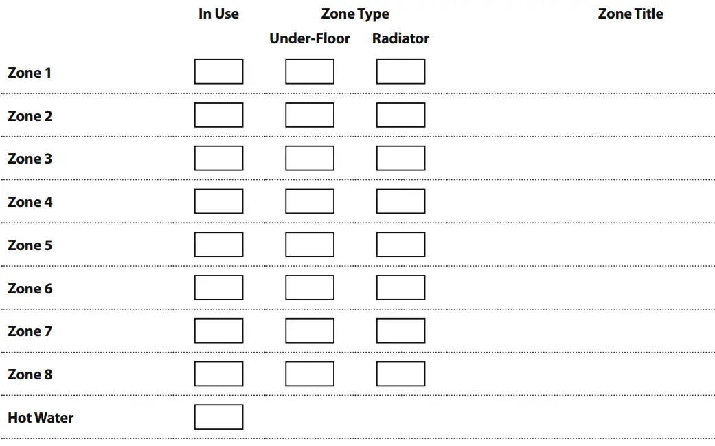
Want More Information?
Call our support team on: +44 (0)1254 669090
Or view technical specifications directly on our website: www.heatmiser.com Twitter: @heatmiseruk
Facebook: facebook.com/thermostats
Heatmiser UK Ltd Units 1-5 Hurstwood Court, Mercer Way Shadsworth Business Park, Blackburn, Lancashire, BB1 2QU, United Kingdom.
Products Commonly used with the UH8-RF V2 wiring centre.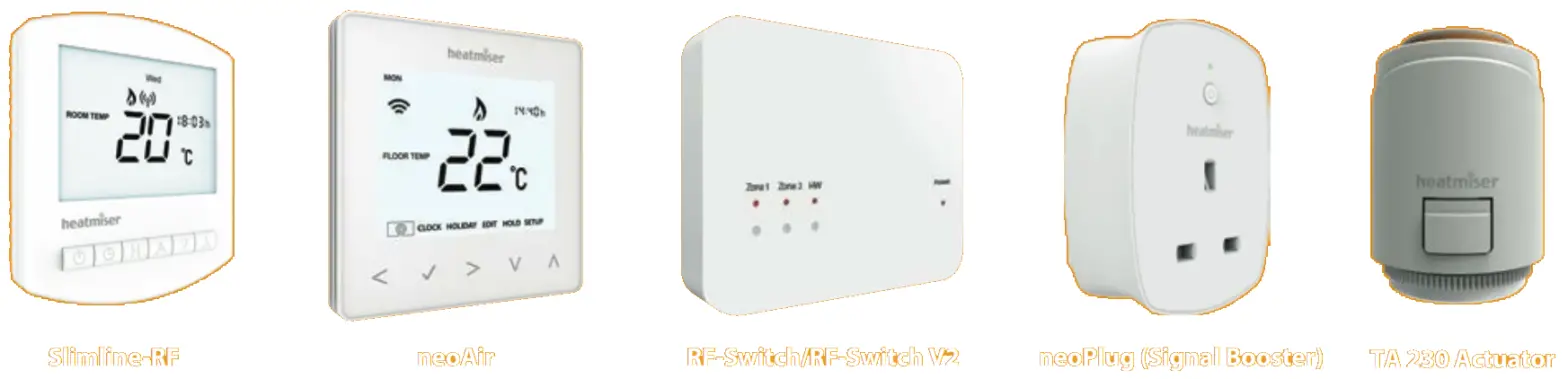
![]()


