Super Bright LEDs BRI619 0-10 Volt Low Voltage PIR Motion Sensor

Safety and Notes
- The product should be installed and serviced by a certified electrician in accordance with applicable national, state, and local building and electrical codes.
- To reduce the risk of electric shock, ensure that the main power source and circuit breakers are switched off before performing any installation or wiring procedures.
Specifications
| Model | BRI619 |
| Maximum Detection Radius | 29.5 ft (9 m) |
| Maximum Mounting Height | 39.4 ft (12 m) |
| Operating Temperature | -40°–167° F (-40°–75° C) |
| Dimming | 0–10 V¹ |
Default Settings
| Model | Sensitivity | Hold On Time | Daylight Sensor | Dimming Level | Dimming Time |
| BRI619 | 100% | 15 min | 30 lux | 30% | 60 minutes |
DIP Switch Settings
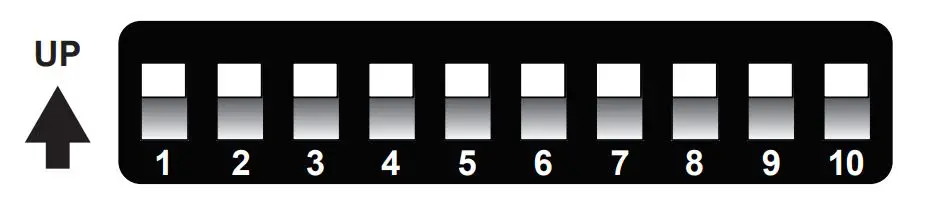
| Setting | Sensitivity | Time | Light | Standby Level | Standby Time |
| Switch Pair Position | 1 and 2 | 3 and 4 | 5 and 6 | 7 and 8 | 9 and 10 |
|
| 20% | 10 seconds | disabled | 0% | always on |
|
| 50% | 1 minute | 10 lx | 10% | 1 minute |
|
| 75% | 5 minutes | 30 lx | 30% | 30 minutes |
|
| 100% | 15 minutes | 50 lx | 50% | 60 minutes |
- Sensitivity adjusts detection range.
- Time adjusts the amount of time before the light enters standby mode when no motion is detected.
- Light adjusts the ambient light threshold (photocell operation).
- Standby Level adjusts the dimming level in standby mode.
- Standby Time adjusts the amount of time between entering standby mode and fully disabling light.
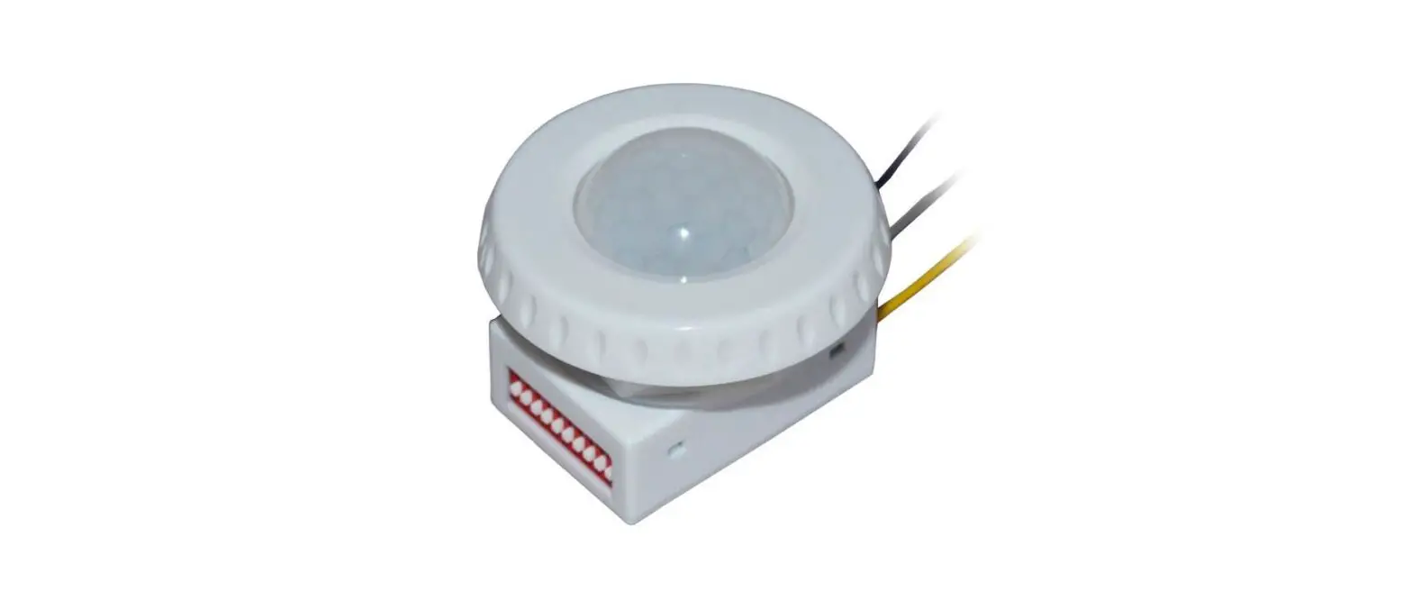
Motion Sensor
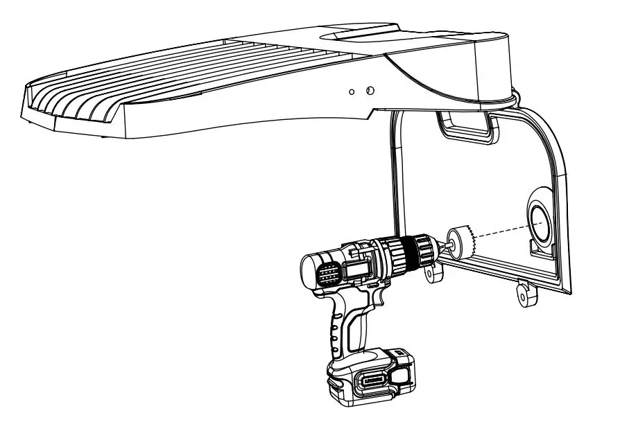
Installation
- Remove supply power from
- Remove two bolts to open access
- Drill 1 5/16 in. hole in pre-marked
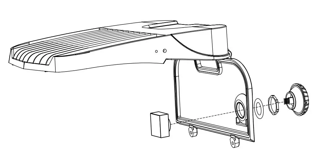
- Place module through hole, then install rubber gasket and locking
- Plug sensor into
- Wire using wiring diagram
- Close and secure panel then reapply supply.
Wiring Diagram
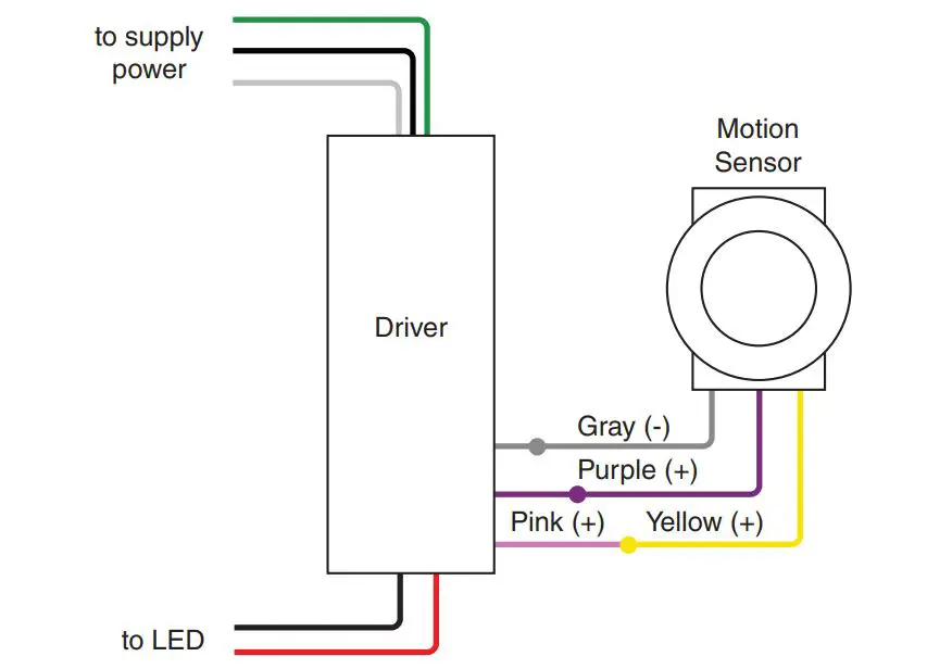
Note: Sensor uses 12–24 VDC input only


