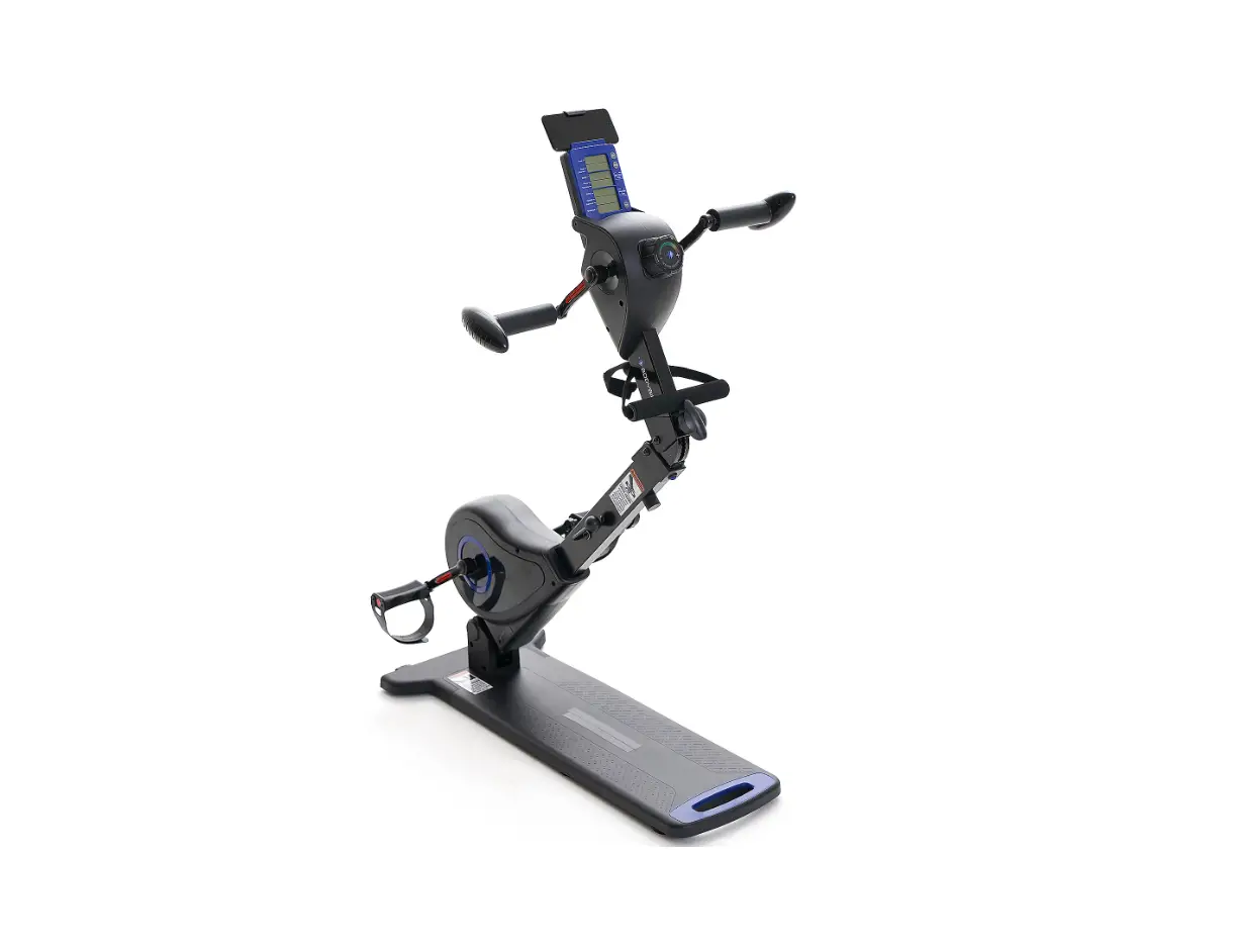
FITNATION F14397 Full Body Bike Instruction Manual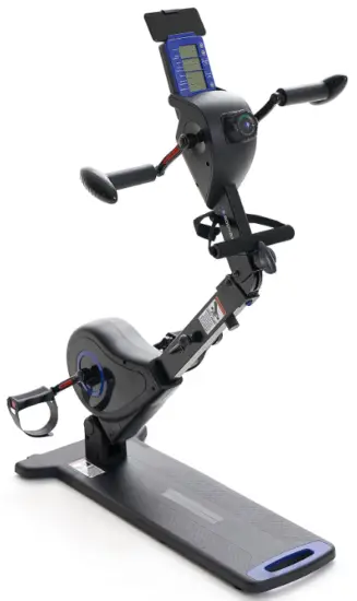
SAFETY INFO & WARNINGS
WARNING
Before starting any exercise program, consult with your physician or health professional, especially if you are above 35 years old or have a health condition.
ATTENTION
- Save these instructions and ensure that other users read this manual prior to using the Body Bike for the first time.
- Read all warnings and cautions posted on the Body Bike.
- The Body Bike should only be used after a thorough review of the manual. Make sure that it is properly assembled and tightened before use.
We recommend that two people be available for assembly of this product. - Keep children under the ape of J3 away from the Body Bike. Do not allow children to use or play on the Body Bike. Keep children and pets away from the Body Bike while it is in use.
- The Body Bike is not a freewheeling exercise bike; therefore, pedal speed should be reduced in a controlled manner to prevent injury from spinning pedals.
- It is recommended that you place this exercise equipment on an equipment mat.
- Set up and operate the Body Bike on a solid, level surface. Do not position the Body Bike on loose rugs or uneven surfaces.
- Make sure that adequate space is available for access to and around the Body Bike.
- Keep fingers clear of all pinch points when folding and unfolding the Body Bike.
- Before using, inspect the Body Bike for worn or loose components. Securely tighten or replace any worn or loose components prior to use.
- Each user should adjust the angle of upper and bottom tension control system per instruction.
- Do not attempt to adjust the angle of upper and bottom tension control system while you are using the Body Bike.
- Make sure the folding mechanism is fully locked before use.
- Consult a physician prior to starting an exercise program and follow their recommendation in developing your fitness program. If at any time during exercise you feel faint, dizzy, or experience pain, stop immediately and consult your physician.
- Always choose the workout which best fits your physical strength and flexibility level. Know your limits and train within them. Always use common sense when exercising.
- Do not wear loose clothing while using the Body Bike.
- Never exercise barefoot or while wearing only socks. Always wear proper footwear for running, walking, or crossing training. Wear shoes that fits well, provides foot support, and has non-skid rubber soles.
- Be careful to maintain your balance while using, mounting, dismounting, or assembling the Body Bike. Loss of balance may result in serious injury.
- The maximum weight capacity of the Body Bike is 248 lbs (U3 kp).
- The Body Bike should be used by only one person at a time.
- The Body Bike is for consumer use only. It is not for use in public or commercial facilities.
Requires 2 AA batteries (1.5 V each). Do not mix old and new batteries. Do not mix alkaline, standard (carbon-zinc), or rechargeable (NiCd, Ni-Mh, etc) batteries.
NOTE: This equipment has been tested and found to comply with the limits for a Class B digital device, pursuant to Pa rt 15 of the FCC Rules. These limits are designed to provide reasonable protection against harmful interference in a residential installation. This equipment generates, uses and can radiate radio frequency energy and, if not installed and used in accordance with the instructions, may cause harmful interference to radio communications.
However, there is no guarantee that interference will not occur in a particular installation. If this equipment does cause harmful interference to radio or television reception, which can be determined by turning the equipment off and on, the user is encouraged to try to correct the interference by one or more of the following measures:
- Reorient or relocate the receiving antenna;
- Increase the separation between the equipment and receiver;
- Connect the equipment into an outlet on a circuit different from that to which the receiver is connected;
- Consult the dealer or an experienced radio/TV technician for help.
EXPLODED DIAGRAM
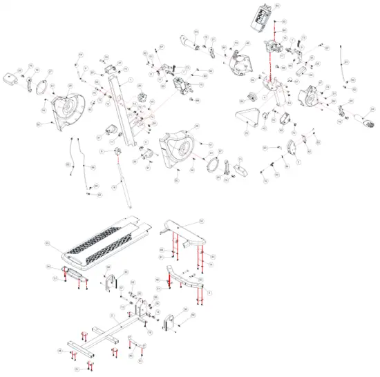
PARTS LIST
| # | PARTS NAME | QTY | # | PARTS NAME | QTY |
| 1. | Upright Post | 1 | 48. | Feet Cushion | 6 |
| 2. | Base Frame | 1 | 49. | Adjustment Lever Handle | 1 |
| 3. | Front Base Support | 1 | SO. | Phillips Head Screw, ST4.2×10 mm | 4 |
| 4. | Post for Upper Body System | 1 | 51. | Phillips Head Screw, ST4.2×16 mm | 28 |
| 5. | Folding Joint | 1 | 53. | Compression Spring | 1 |
| 6. | Cylinder Bracket | 1 | 54. | C Ring 10X § 5X0.8t | 1 |
| 7. | Magnet Holder | 2 | 55. | Socket Head Cap Screw, M8x4Omm | 2 |
| 8. | Magnet Bracket | 2 | 56. | Button Head Cap Screw, M8x55 mm | 2 |
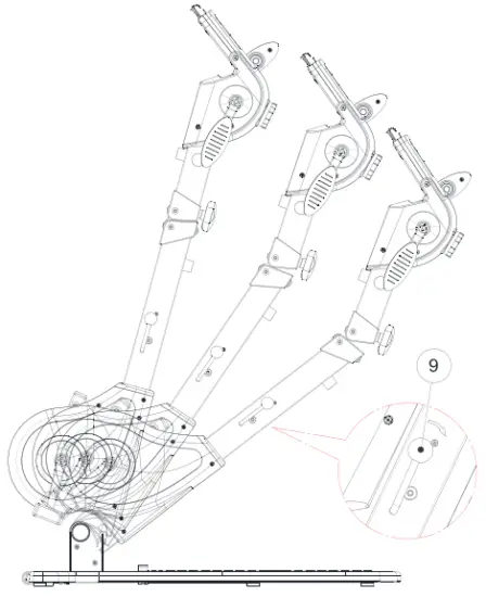
| 9. | Adjustment Lever | 1 | 57. | Button Head Cap Screw, M8x60mm | 1 |
| 10. | Folding Joint Pin | 1 | 58. | Nylon Nut M8 (Thicker) | 3 |
| 11. | Adjustment Collar | 2 | 59. | Phillips Head Screw, M5x10 mm | 8 |
| 12. | Upper Collar for Cylinder | 2 | 60. | Phillips Flat Head Head Screw, | 1 |
| 13. | Bottom Collar for Cylinder | 2 | M5x2Omm | ||
| 14. | Transport Wheel Spacer | 2 | 61. | Spring Washer M5 | 4 |
| 15. | Resistance Mechanism for | 1 | 63. | Phillips Head Screw, M5x12 mm | 2 |
| Feet System | 64. | Button Head Cap Screw, M6x10 mm | 12 | ||
| 16. | Resistance Mechanism for | 1 | 65. | Phillips Head Screw, M4x12mm | 2 |
| Hand system | 66. | Hex Nut M4 | 2 | ||
| 17. | Magnet | 14 | 67. | Socket Head Cap Screw, M6x35mm | 2 |
| 18. | Cylinder | 1 | 69. | Nylon Nut M6 | 2 |
| 19. | Left Crank for Feet System | 1 | 70. | Button Head Cap Screw, M8x45 mm | 3 |
| 20. | Right Crank for Hand System | 1 | 71 | Flat Washer M8 | 2 |
| 21. | Left Crank for Hand System | 1 | 72. | Nylon Nut M8 (Thinner) | 4 |
| 22. | Right Crank for Hand System | 1 | 73. | Compression Spring 4)9*4)0.8*45L | 2 |
| 23. | Left Handlebar | 1 | 74. | Button Head Screw, M6x26mm | 2 |
| 24. | Right Handlebar | 1 | 75. | Hex Head Screw M8x20mm | 4 |
| 25. | Left Housing for Feet System | 1 | 76. | Wrench #13-#15 | 1 |
| 26. | Right Housing for Feet System | 1 | 77. | Allen Wrench T6 | 1 |
| 27. | Housing Ring | 1 | 78. | Phillips Rounded Head Screw, | 2 |
| 28. | Upper Tension Control Knob | 1 | ST4.2×25 mm | ||
| 29. | Bottom Tension Control Knob | 1 | 79. | Balancing Handle | 1 |
| 30. | Left Pedal | 1 | 80. | Monitor | 1 |
| 31. | Right Pedal | 1 | 81. | Pen Sensor for Hand System | 1 |
| 32. | Front Base Cover | 1 | 82. | Sensor Base | 2 |
| 33. | Main Base Cover | 1 | 81 | Sensor Wire | 1 |
| 34. | Bottom Base Cover | 1 | 84. | Pen Sensor for Feet System | 1 |
| 35. | Left Bottom Joint Cover | 1 | 85. | Connection Bandage | 1 |
| 36. | Right Bottom Joint Cover | 1 | 87. | Upper Cushion | 1 |
| 37. | Left Upper Joint Cover | 1 | 88. | Sensor Holder | 2 |
| 38. | Right Upper Joint Cover | 1 | 89. | Washer | 4 |
| 39. | Folding Button | 1 | 90. | Rubber Pad | 1 |
| 40. | Upper Folding Joint Cover | 1 | 91. | Phillips Rounded Head Screw, | 4 |
| 41. | Bottom Folding Joint Cover | 1 | ST4.2 x13 mm | ||
| 42. | Front Folding Joint Cover | 1 | 92. | Phillips Head Screw, M5x10 mm | 4 |
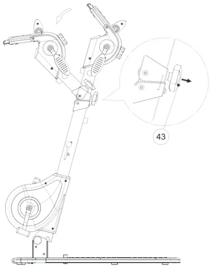
| 43. | Folding Joint Knob | 1 | 93. | Hex Nut M4x12 mm | 2 |
| 44. | Transport Wheel | 2 | 94. | Bandage | 1 |
| 45. | Bottom Cushion | 1 | |||
| 46. | Left Housing for Hand System | 1 | |||
| 47. | Right Housing for Hand System | 1 | |||
HARDWARE LIST

- Socket Head Cap Screws M8*4O mm ( •2)
- Wrench #13 and #15
- Allen Wrench T6
PRODUCT DESCRIPTION
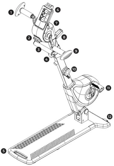
- Left Handlebar
- Upper Tension Control Knob
- Balancing Handle
- Folding Button
- Main Base Cover
- Monitor
- Housing for Hand System
- Bandage
- Right Handlebar
- Bottom Tension Control Knob
- Pedal
- Transport Wheel
ASSEMBLY
ATTENTION: Fully tiphten all screws before starting workout.
Please read the instructions carefully.
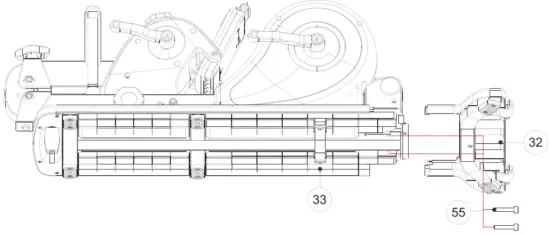
- STEP 01
Attach #32 Front Base Cover onto #33 Main Base Cover with: #55 Socket Head Cap Screw M8*4O mm.
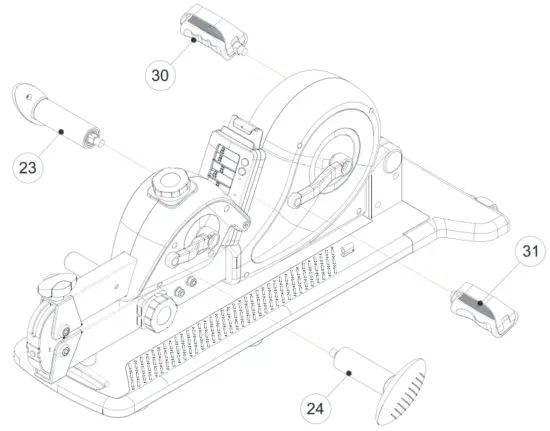
- STEP 02
Attach #2Z/24, Left/ Right Hand labors and #30/31, Left/ Right Pedals.
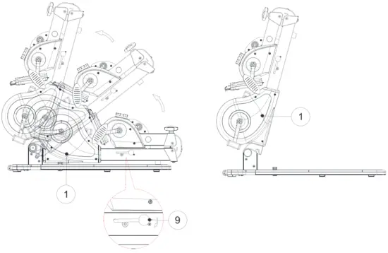
- STEP 03
Push down #9 Adjustment Lever to lift up #l Upright Post. Adjust appropriate angle by pushing down the same lever.
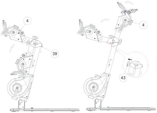
- STEP O4
Life up #4 Post for Upper Body System and rotate it forward to lock with #39 Folding Button. Then tighten #43 Folding 3oint Knob. To adjust the angle of the post, loosen #43 and the re-tighten it once it’s moved to the comfortable position.
TENSION ADJUSTMENT
RESISTANCE LEVELS
The resistance levels a re represented by the preen, yellow, and red areas on the #28/29 Tension Control Knobs. Be sure to select a resistance range you are most comfortable with.
Green = Lower Resistance Levels
Yellow = Medium Resistance Levels
Red = Higher Resistance Levels.
INCREASE RESISTANCE
To increase resistance level, rotate #28 Upper Tension Control Knob or #29 Bottom Tension Control Knob clockwise toward the “+” symbol by the red area.
DECREASE RESISTANCE
To decrease resistance level, rotate the knobs counter-clockwise toward the “—” symbol by the green area.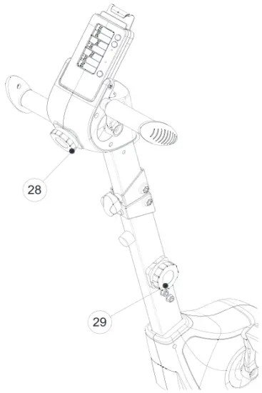
ANGLE ADJUSTMENT
- STEP 01
Loosen #43 Folding Knob by turning it counter-clockwise. Push #46/ 47 Housing for Hand System backward to appropriate angle for your workout.
- STEP 02
Push down #9 Adjustment Lever to adjust #1 Upright Post.
MONITOR ADJUSTMENT
Bottom Tension Control Knob clockwise.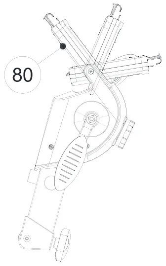
FOLDING
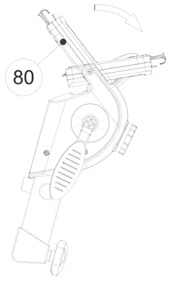
- STEP O1
Rotate #80 Monitor forward.
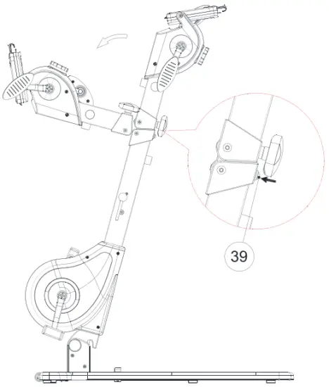
- STEP 02
Press #39 Folding Button to fold down the upper part of the Body Bike.
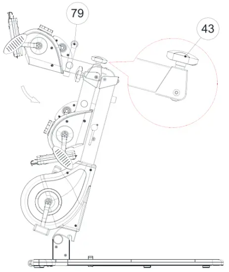
- STEP 03
Hold #79 Balancing Handle and loosen #43 Folding Knob by turning it counter-clockwise. Push #46/47 Housing for Hand System fully backwards.
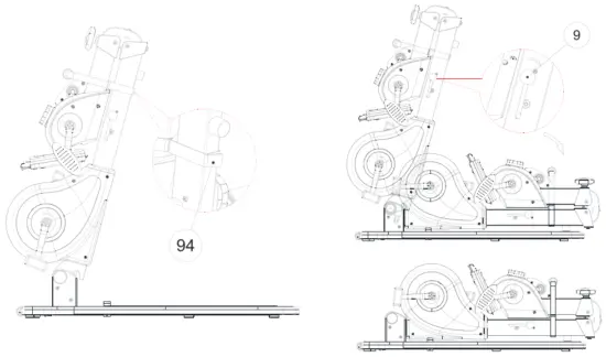
- STEP O4 & O5
Wrap and tighten both posts together with #94 Bandage.
Push down #9 Adjustment Lever to fully fold down the whole unit.
NOTE: Please keep #94 Bandage tightened on both posts. Do not un-tighten it.
- STEP 06
To move the Body Bike in fold ng position, push down #9 Adjustment Lever to lift u p the post slightly in order to have enough space for grabbing the blue handle. Hold the blue handle tightly and move the whole unit with #44 Transport Wheel.

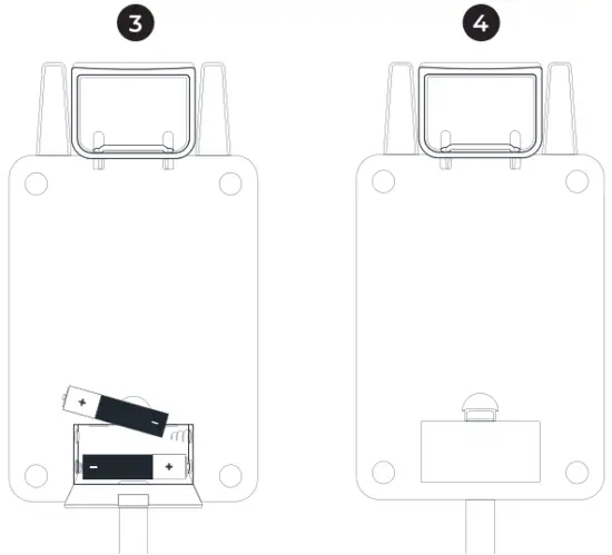
BATTERY INSTALLATION
BATTERY REQUIREMENTS
The monitor operates with two AA batteries (J.5V each).
BATTERY INSTALLATION
Locate the battery compartment cover on the back of the monitor. Remove the back cover and insert two AA batteries according to the correct polarity as shown. Replace the cover.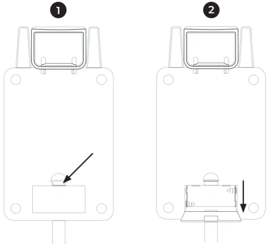
CONSOLE OPERATION
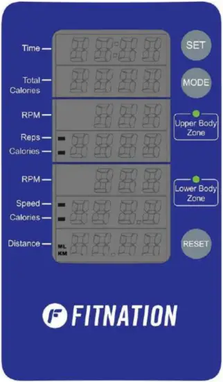
DISPLAY DEFINITION
POWER ON
Move the pedals, handlebars, or press any button. All displays will show for 2 seconds before entering stand by mode after installing batteries.
POWER OFF
Automatically shuts off after 4 minutes of inactivity. Display enters stand by mode after 4 seconds of inactivity.
TIME
Shows duration of exercise.
Display Range: OO:OO 99.59
Setting Range: 0 99 minutes. The minimum adjustable value Is l minute.
TOTAL CALORIES
Displays calories burned during exercise.
Display Range: 0 9999
Setting Range: 0 – 9999 minutes. The minimum adjustable value is 10 Kcal.
RPM – UPPER BODY
Displays revolutions per minute for arm exercise.
Display Range: 0 999
RPM – LOWER BODY
Displays revolutions per minute for leg exercise.
Display Range: 0 999
REPETITIONS
Displays the number of rotations completed for upper body exercise.
Display Range: 0 9999
Setting Range: 0 – 9999. The minimum adjustable value is 10.
CALORIES – UPPER BODY
Displays calories burned for arm exercises.
Display Range: 0 9999
Setting Range: 0 9999. The minimum adjustable value is local.
CALORIES – LOWER BODY
Displays calories burned for leg exercises.
Display Range: 0 9999
Setting Range: O 9999. The minimum adjustable val ue is loKcal.
SPEED
Displays the speed of leg exercise.
Display Range: 0 999.9
DISTANCE
Displays distance traveled d uring exercise.
Display Range: 0 99.99 KM or Miles
Setting Range: 0 – 99.99 KM or Miles. The minimum adjustable val ue is 1 KM/Mile.
SCAN
Automatically scans REPS, CALORIES (U PPER BODY), SPEED, and CALORIES (for LOWER BODY) in sequence every six seconds.
CONTROL BUTTON DEFINITION
MODE BUTTON
Select functions for value setting in sequence. TIME e REPETITIONS CALORIES (UPPER BODY) + CALORIES (LOWER BODY) DISTANCE
SET BUTTON
Press SET button for adjusting the value of each function. Press the button once to increase the setting value by one. Press and hold the button to continuously increase the setting value.
Time: Minimum value is J minute.
Total Calories: Minimum value is 10 Kcal
Repetitions: Minimum value is JO times.
Calories (for Upper Body): Minimum value is 10 Kcal.
Calories (for Lower Body): Minimum value is 10 Kcal.
Distance: Minimum value is 1 KM or Mile.
RESET BUTTON
Press RESET button to clear the setting value in each function. Press and hold the button for 2 seconds to clear the setting values for all functions.
SWITCH DISTANCE UNIT
Press “SET” and “RESET” buttons together for over 5 seconds. KM or Miles appears on the left right corner under Distance Display.
QUESTIONS?
CONTACT CUSTOMER SERVICE
833-937-2453
![]() Read Instructions Before Operating
Read Instructions Before Operating
ECHELONFIT.COM
For questions, assistance, or replacement parts, do not return to your retailer. Contact Echelon” customer service below. For refunds on items not purchased from Echelon’ directly, please contact your retailer.
ECHELON° FIT 1-YEAR LIMITED WARRANTY
Echelon’ warrants this product to be free of manufacturing defects. Should any such defect develop or become evident within one year from the date of purchase, Echelon’ will replace the entire product or, at its option, repair or replace the defective part(s) without charge. Contact Echelon’ customer service at 833-937-2453 or at [email protected] to determine whether it is necessary to return the unit. To return, securely pack the entire unit. Be sure carton clearly identifies sender by name and address. Attach a letter or card describing defect and original sales receipt. Mail prepaid to Echelon Fitness Multimedia, LLC 6011 Century Oaks Dr. Chattanooga, TN 37416. This warranty is void if damage or malfunction is due to abuse or failure to operate product in accordance with instructions and on recommended electrical current. This warranty gives you specific legal rights and you may also have other rights which vary from state to state. If you have any questions, or would like to learn more about Echelon’, please contact us at 833-937-2453 or at [email protected].
Register your product online at echelonfit.com/pages/register-warranty/
Customer Service
![]() 833-937-2453 (+1.423.402.9010)
833-937-2453 (+1.423.402.9010)![]() [email protected]
[email protected]
Model: BODYBI KE-FN
DO NOT DISPOSE OF BATTERIES IN FIRE. ALWAYS DISPOSE OF BATTERIES PER LOCAL & FEDERAL GUIDELINES.
© 2021 ECHELON FITNESS MULTIMEDIA, LLC. All specifications are subject to change without notice. All rights reserved. Echelon Fitness Multimedia, LLC 6011 Century Oaks Dr. Chattanooga, TN 37416