 FuelTech- PR0600 -Wiring- Harness
Presentation
The FuelTech PRO600 harness is the proper link between the FuelTech FT600 ECU and all of your engine sensors and actuators. This harness has all the components needed to make a plug’n’play installation on an engine. It has all the relays and fuses needed for the system on a standard setup, a firewall connector to make it easier to remove and every connector has its own label. The insulation and connectors are humidity, heat and oil resistant.
Specifications:
- 8 or 16 injector outputs(For 16 injectors a secondary injector harness is required)
- 2 FuelTech Peak and Hold external drivers ready
- Dual FuelTech WB-Nano O2 ready
- FuelTech Alcohol O2 dual channel (Adapter harness required)
- GM Style intake air temperature sensor ready
- GM Style engine temperature sensor ready
- 4 pressure sensor ready for fuel, oil wastegate and back-pressure/another 0-5V sensor
- High output relays
- 3 Extra output connectors for generic use.
- 1 Extra Inputs connector for generic use.
- Firewall CPC Connector
- Crank and Cam connectors (hall and VR options)
- FuelTech EGT-8 ready
Dimensions (in package): 20” x 20” x 5”
Weight: 11 lbs.
Warnings and Warranty Terms
The use of this equipment implies in total accordance with the terms described in this manual and exempts the manufacturer from any responsibility regarding to product misuse.
Read all the information in this manual before starting the product installation. This product must be installed and tuned by specialized auto shops and/or personnel with experience on engine tuning.
Before starting any electrical installation, disconnect the battery. The inobservance of any of the warnings or precautions described in this manual might cause engine damage and lead to the invalidation of this products warranty. The improper adjustment of the product might cause engine damage. This product does not have a certification for the use on aircrafts or any flying vehicles, as it was not designed for such use or purpose. In some countries where an annual inspection of vehicles is enforced, no modification in the OEM ECU is permitted. Be informed about local laws and regulations prior to the product installation.
Limited Warranty
All products manufactured by FUELTECH are warranted to be free from defects in material and workmanship for one year following the date of original purchase. Warranty claim must be made by original owner with proof of purchase from an authorized reseller. This warranty does not include sensors or other products that FUELTECH carries but did not manufacture. If a product is found defective, such products will, at FUELTECH’s option, be replaced or repaired at no cost. All products alleged by Purchaser to be defective must be returned to FUELTECH, postage prepaid, within the one year warranty period. This limited warranty does not cover labor or other costs or expenses incidental to the repair and/or replacement of products or parts. This limited warranty does not apply to any product which has been subject to misuse, mishandling, misapplication, neglect (including but not limited to improper maintenance), accident, improper installation, tampered seal, modification (including but not limited to use of unauthorized parts or attachments), or adjustment or repair performed by anyone other than FUELTECH. The parties hereto expressly agree that the purchaser’s sole and exclusive remedy against FUELTECH shall be for the repair or replacement of the defective product as provided in this limited warranty. This exclusive remedy shall not be deemed to have failed of its essential purpose so long as FUELTECH is willing and able to repair or replace defective goods. FUELTECH reserves the right to request additional information such as, but not limited to, tune up and log files in order to evaluate a claim. Seal violation voids warranty and renders loss of access to update releases.
Overview
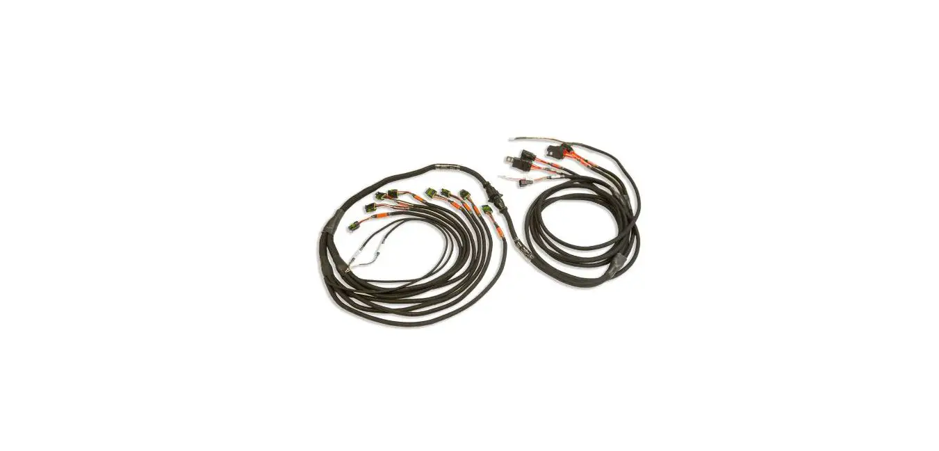
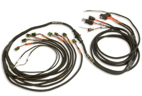
The FuelTech PRO600 Wiring Harness is a complete plug n’ play wiring solution to be used with a FuelTech FT600 ECU. It has all the connectors, relays and fuses directly built-in and can be used with nearly any application with 8 injectors (expandable up to 16 injectors).
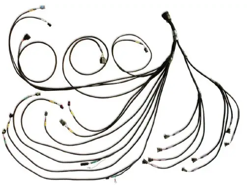
PRO600 V8 Harness
The PRO600 is a FuelTech FT600 harness designed for systems with up to 16 staged injectors(dual banks), distributor or COP coils and FuelTech Wideband Nano O2 dual channel with Bosch LSU 4.2 sensors to run sequential, semi-sequential or multipoint injection. It is already wired for 2 FuelTech Peak and Hold drivers for setups utilizing 8 low impedance injectors, for 8 more injectors a secondary injector harness is required. When using high impedance injectors, Peak and Holds are not needed. In this case, only a bypass connector (jumper wires sold separately) is required. There are 2 relays to power the complete system, separating the injectors from the electronics.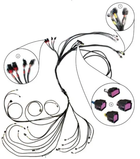
- Connector A, B and CAN of FT600;
- Relays and fuse;
- Auxiliary connectors;
Versions and components
To make it easier to install and to do services in the engine/car, the PRO600 Harness is modular, so you can disconnect the engine side of the harness from the rest of it. Below are all of the parts contained in the basic version:
PRO600 V8 components
Main/Outputs (Inner)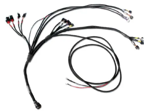
This is the section that will be installed in the inner side of the car. On this part you will find the connections to all the units, the wires related to the power supply (+12V to battery, ground to battery, ground to chassis, +12V switched), relays and fuses. Check below to see all of the connectors and where they are connected:
- FuelTech FT600 A and B connectors: Direct connection to FT600, both connectors must be securely installed.
- 2x FuelTech Peak and Hold: These are the driver modules needed to fire low impedance injectors. When the system uses high impedance injectors, jumper wires are required (sold separately). If the Peak and Hold or the jumper wires are not being used, the injectors will not fire.
- FuelTech Wideband Nano O2 dual channel: This connector goes to the FuelTech Wideband Nano O2 module, it’s capable of reading the Bosch O2 sensors and send the information to log in the T600.
- 2x 40A Relay: The system has 2 relays to power everything. The Main Relay powers the ECU, Wideband Nano O2, Peak and Hold drivers, sensors and Outputs B connector. The Injector Relay powers only the primary injectors.
- +12V Switched wire: This wire goes to the ignition key and is responsible for turning on all the relays.
- Battery ground and battery positive: It is the system power supply and must be connected exactly as the following: Battery (+) goes directly to the battery’s positive or kill switch. Battery (-) MUST GO ONLY on the battery’s negative terminal.
- CAN A and CAN B Connectors: CAN A receives any other FuelTech module that communicates through CAN ports. CAN B is used to eliminate the Racepak interface module.
- Aux Power: Power output straight from the battery to connect with secondary injector harness.
- Output Connectors: Outputs A has 8 blue wires to use as general output or to connect to secondary injector harness. Outputs B has 8 gray wires to use as general output or to connect to coil harness. Outputs C has 8 yellow wires to use as general outputs.
- Inputs Connector: Inputs connector has 13 white wires to use as general inputs for 0 to 5V analog sensors.
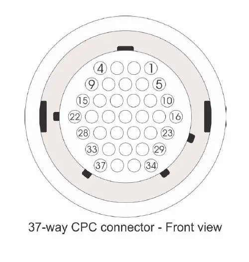
- Main Inner 37-way circular: The Main connector is a 37-way Tyco CPC connector which contains all necessary inputs to run an engine.
- POWERED CAN A connector: Ready to plug in connector with power, ground and CAN A communication wires. This connector can be attached to the firewall.
Main Engine
- Female 37-way circular connector: The Main connector is a 37- way Tyco CPC connector which contains all necessary inputs to run an engine. There you will find the following connectors: O2 sensors, Crank Trigger Sensor, Cam Sync Sensor, TPS, Oil Pressure, Fuel Pressure, Wastegate Pressure, Points, Engine Temperature, Intake Air Temperature, Back Pressure or any 0-5V sensor and the 8 injectors.
- Throttle position sensor: The TPS measures the throttle position. The PRO600 harness has a 3-way Weather Pack connector and almost any 0-5V TPS can be used.
- Back pressure sensor: This input can be used to read the back pressure, any other pressure with a FuelTech PS sensor or any 0- 5V sensor. It also can read an external MAP sensor.
- FuelTech EGT-8: Ready to plug FuelTech EGT-8 module (sold separately).
- Fuel pressure sensor: This input can be used to read fuel pressure using a FuelTech PS sensor or SSI P51 Packard sensor.
- Oil pressure sensor: This input can be used to read oil pressure using a FuelTech PS sensor or SSI P51 Packard sensor.
- Crank trigger sensor (Hall effect or variable reluctance): PRO600 harness is ready for both MSD crank trigger (VR) and FT Hall Effect RPM/speed sensor (5005100083).
- Cam sync sensor (Hall effect or variable reluctance): PRO600 harness is ready for both Pro Mag 44 trigger (with mods) and FT Hall Effect RPM/speed sensor (5005100083).
- Engine temperature sensor: Ready for GM style CLT sensor.
- Intake air temperature sensor: Ready for GM style IAT sensor.
- 2x Bosch wideband O2 sensors: Designed for Bosch LSU 4.2 O2 sensors.
- 8x fuel Injector outputs (primary bank): 8 injector outputs (EV1 connector) which allows sequential fuel injection and individual fuel cylinder trim.
- POWERED CAN A connector: Ready to plug in connector with power, ground and CAN A communication wires.
PRO600 V8 Secondary injectors extension harness components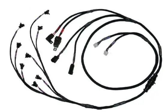
This is the extension harness required to run a secondary bank of injectors. It has 8 additional injector and 2 additional peak and hold connectors, a relay and a fuse. Check below to see all of the connectors and where they are connected:
- 2x FuelTech Peak and Hold: These are the driver modules needed to fire low impedance injectors. When using high impedance injectors, jumper wires are required (sold separately). If the Peak and Hold or the jumper wires are not being used, the injectors will not fire.
- 1x 30A Relay: This Relay will power the injectors.
- Aux Power: This connector goes to the Aux Power on the PRO600 harness and is responsible for turning on the relay.
- Outputs A connector: This connector must be plugged on the “Outputs A” connector on the PRO600 harness.
- 8x fuel injector outputs (secondary bank): 8 injector outputs (EV1 connector) which allows sequential fuel injection and individual fuel cylinder trim.
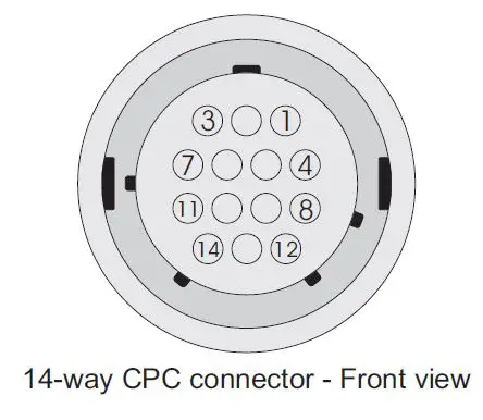
- Main Inner 24-way circular: The Main connector is a 24-way Tyco CPC connector which contains the outputs to the additional 8 injectors. This connector can be attached to the firewall.
PRO600 V8 Smart Coil harness components
This extension allows the use of 8 individual Smart COP coils(w/ integrated igniter) on the ignition system, it has 8 metri-pack 150.2 connectors, 1 relay and 1 fuse (or 2 relays and 2 fuses on the second generation). Check below to see all of the connectors and where they are connected, as well as instructions and specific information for both generations:
Standard components for both generations:
- Main Inner 24-way circular: The Main connector is a 24-way Tyco CPC connector that contains the outputs to the 8 individual coils.
- 8x Smart coil connectors: 8 Smart COP coil outputs (metric- pack 150.2 connectors) which allows either sequential or wasted spark ignition.
First-generation:
- 1x 30A Relay: This Relay will power the coils
- Outputs B connector: This connector must be plugged into the “Outputs B” connector on the PRO600 harness.
WARNING:
Making changes to the map using FTManager then writing to the ecu with car power on or with a battery charger on it may possibly damage the coils or blow the fuse.
Second generation:
- 2x 30A Relay: These Relays will power the coils.
- Outputs B connector: This connector must be plugged into the “Outputs B” connector on the PRO600 harness, To prevent damage of the coils, the separate red wire must be wired to a yellow output in the outputs C connector, the selected yellow output must be set up as a RPM activated output on the map(refer to instructions below). If no yellows are available, this red wire can be inserted in the vacant pin J or a separate switched 12v (With the risk of maybe damaging the coils if ignition is left on for long periods of time).
WARNING:
When not using a RPM activated output to trigger the relays, making changes to the map using FTManager then writing to the ecu with car power on or with a battery charger on it may possibly damage the coils or blow the fuse.
Setting up RPM Activated Output and testing the coils:
To set up a yellow output as a RPM Activated Output to trigger the coil relays follow these instructions:
On FTManager: go to Engine Settings>Map options>Other functions then check the RPM activated output checkbox, click on it to go to the set up menu, next change “Enable with RPM above” to 20 and Output signal to Activated at 12v, then go to Sensors and Calibration>Outputs and change the yellow output selected for this to “RPM activated output”.
On ECU: Go to Other functions>RPM activated output, first select the yellow output, next select “enable”, then on the last screen change the output activation to Activated at 12v.
When using the test feature on the outputs menu available on FTManager to test the coils, you must first change the RPM activated output setting to 0 RPM, so as to trigger the relays with the engine off.
Labels
All connectors have proper labels to identify each one. They are labeled by color and description name. The colors are related to their functions:
- Green: The green labels are related to the RPM sensors (Crank Trigger and Cam Sync)
- Yellow: Input sensors such as TPS, Engine Temp, Air temp, Fuel Pressure, Oil Pressure, Back Pressure or any other 0-5V sensor
- Blue: Exclusively to O2 sensors (NTK or Bosch)
- White: Outputs and Extra connector, Points, CAN
- Purple: Peak and Hold and fuel injectors (Primary bank)
- Brown: Peak and Hold and fuel injectors (Secondary bank)
- Black: FT600, Main connector, Battery (-), Power Ground
- Red: Battery (+), Main and Injectors relays/fuses
Diagrams
PRO600 diagrams
Connector A – PRO600
| FT600 #Pin | Wire color | #Pin | Connector | Function |
| 1 | Blue #1 | 4 | Peak and Hold (L) | #1 injector |
| 2 | Blue #2 | 4 | Peak and Hold (R) | #2 injector |
| 3 | Blue #3 | 2 | Peak and Hold (L) | #3 injector |
| 4 | Blue #4 | 2 | Peak and Hold (R) | #4 injector |
| 5 | Blue #5 | 5 | Peak and Hold (L) | #5 injector |
| 6 | Blue #6 | 5 | Peak and Hold (R) | #6 injector |
| 7 | Blue #7 | 1 | Peak and Hold (L) | #7 injector |
| 8 | Blue #8 | 1 | Peak and Hold (R) | #8 injector |
| 9 | Blue #9 | A | Outputs A | Generic output #1 |
| 10 | Blue #10 | B | Outputs A | Generic output #2 |
| 11 | Blue #11 | C | Outputs A | Generic output #4 |
| 12 | Blue #12 | D | Outputs A | Generic output #5 |
| 13 | Blue #13 | E | Outputs A | Generic output #6 |
| 14 | Blue #14 | F | Outputs A | Generic output #7 |
| 15 | Blue #15 | G | Outputs A | Generic output #7 |
| 16 | Blue #16 | H | Outputs A | Generic output #8 |
| 17 | Black/white | – | Power Ground | Power Ground |
| 18 | Grey #1 | A | Outputs B | Generic output #1 |
| 19 | Grey #2 | B | Outputs B | Generic output #2 |
| 20 | Grey #3 | C | Outputs B | Generic output #3 |
| 21 | Grey #4 | D | Outputs B | Generic output #4 |
| 22 | Grey #5 | E | Outputs B | Generic output #5 |
| 23 | Grey #6 | F | Outputs B | Generic output #6 |
| 24 | Grey #7 | G | Outputs B | Generic output #7 |
| 25 | Grey #8 | H | Outputs B | Generic output #8 |
| 26 | Yellow #1 | A | Outputs C | Generic output #1 |
| 27 | Yellow #2 | B | Outputs C | Generic output #2 |
| 28 | Yellow #3 | C | Outputs C | Generic output #3 |
| 29 | Yellow #4 | D | Outputs C | Generic output #4 |
| 30 | Yellow #5 | E | Outputs C | Generic output #5 |
| 31 | Yellow #6 | F | Outputs C | Generic output #6 |
| 32 | Yellow #7 | G | Outputs C | Generic output #7 |
| 33 | Yellow #8 | H | Outputs C | Generic output #8 |
| 34 | Red | 87 | Main Relay | Switched W #2 |
Connector B – PRO600
| FT600 #Pin | Wire color | #Pin | Connector | Function |
| 1 | Red (VR)/White (Hall) – Shielded black cable- crank | 2/B | Crank VR/Hall | RPM input – positive signal |
| 2 | Black – Shielded black cable – crank | 1 | Crank VR | RPM input – negative signal |
| 3 | Red (VR)/White (Hall) – Shielded gray cable – cam | B/B | Cam VR/Hall | Cam sync input – positive signal |
| 4 | Black – Shielded gray cable – cam | A | Cam VR | Cam Sync input – negative signal |
| 5 | White #1 | A | Inputs | Generic input #1 |
| 6 | White #2 | C | Back Pressure | BACK PRESSURE input |
| 7 | White #3 | B | Inputs | Generic Input #3 |
| 8 | White #4 | C | Oil Pressure | Oil pressure input |
| 9 | White #5 | A | H2O | Coolant Temperature Input |
| 10 | Black | – | Battery (-) | Power Ground |
| 11 | Yellow/Blue | 3 | CAN_A | CAN_A_LOW |
| 12 | White/Red | 4 | CAN_A | CAN_A_HI |
| 13 | White #6 | C | Fuel Pressure | Fuel pressure input |
| 14 | White #7 | A | Air Temperature | Air temperature input |
| 15 | White #8 | C | Inputs | Generic input #8 |
| 16 | White #9 | D | Inputs | Generic input #9 |
| 17 | White #10 | C | Wastegate Pressure | Wastegate Pressure Input |
| 18 | Black | – | Battery (-) | Ground |
| 19 | Black | – | Battery (-) | Ground |
| 20 | White/Red | 2 | CAN_B | CAN_B_HI |
| 21 | White #11 | B | TPS | TPS input |
| 22 | White #12 | E | Inputs | Generic input #12 |
| 23 | White #13 | F | Inputs | Generic input #13 |
| 24 | White #14 | G | Inputs | Generic input #14 |
| 25 | White #15 | H | Inputs | Generic input #15 |
| 26 | Red | 87 | Main Relay | Switched 12V |
| 27 | Green/Red | B / P | Sensors and inputs connector | 5V supply for sensors |
| 28 | Yellow/Blue | – | CAN_B | CAN_B_LOW |
| 29 | Green/Black | A / S | Sensors and Inputs Connector | Ground for sensors |
| 30 | White #16 | J | Inputs | Generic input #16 |
| 31 | White #17 | K | Inputs | Generic input #17 |
| 32 | White #18 | L | Inputs | Generic input #18 |
| 33 | White #19 | M | Inputs | Generic input #19 |
| 34 | White #20 | N | Inputs | Generic input #20 |
Connector A – base map configuration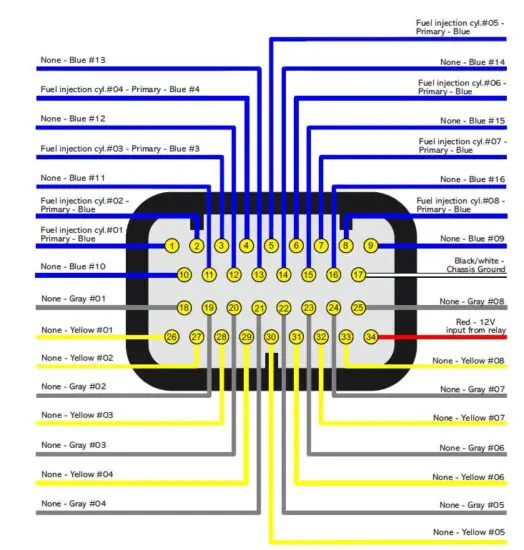
Connector B – base map configuration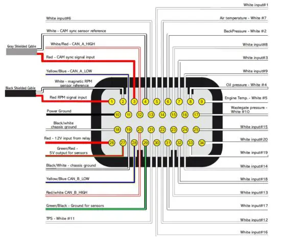
Main engine(37-way CPC connector)
| 37-way #Pin | Wire color | Connector | #Pin | Function | ||
| Inner Side | Engine Side | Inner Side | Engine Side | |||
| 1 | White #7 | FT600 B | Air Temp | 14 | A | Air Temperature Input |
| 2 | White #6 | FT600 B | Fuel Pressure | 13 | C | Fuel Pressure Input |
| 3 | White #5 | FT600 B | H2O | 9 | A | Engine Temperature Input |
| 4 | Black – Shielded cable – Crank | FT600 B | Crank VR | 2 | 1 | RPM Input – Negative Signal |
| 5 | White #4 | FT600 B | Oil Pressure | 8 | C | Oil Pressure Input |
| 6 | White #11 | FT600 B | TPS | 21 | B | TPS Input |
| 7 | Red – Shielded Cable – Cam | FT600 B | Cam VR | 3 | B | Cam Sync Input – Positive Signal |
| White | Cam Hall | |||||
| 8 | Red – Shielded Cable – Crank | FT600 B | Crank VR | 1 | 2 | RPM Input – Positive Signal |
| White | Crank Hall | B | ||||
|
9 |
Green/Red |
FT600 B | TPS |
27 | C |
5V Supply |
| Back Pressure | B | |||||
| Fuel Pressure | ||||||
| Oil Pressure | ||||||
| 10 | White #2 | FT600 B | Back Pressure | 6 | C | Back Pressure Input |
| 11 | Black – Shielded Cable – Cam | FT600 B | Cam VR | 4 | A | Cam Sync Input – Negative Signal |
| 12 | White #10 | FT600 B | Wastegate Pressure | 17 | C | Wastegate Pressure Input |
| 13 | Red | Main Relay | Crank Hall | 87 | A | Switched 12V |
| Cam Hall | ||||||
| EGT-8/Deutsch | 1 | |||||
|
14 |
Green/Black |
FT600 B | Air Temp |
29 | B |
Sensor Ground |
| Fuel Pressure | A | |||||
| H2O | B | |||||
| Oil Pressure | A | |||||
| Back Pressure | ||||||
| TPS | ||||||
| EGT-8/Deutsch | 2 | |||||
| 15 | Yellow/Blue | FT600 B | CAN_A | 11 | 3 | CAN_A_LOW |
| EGT-8/Deutsch | ||||||
| 16 |
Purple | Peak & Hold Left | Injector #1 | 9 |
2 | Primary #1 Injector |
| 17 | Injector #3 | 7 | Primary #3 Injector | |||
| 18 | Injector #5 | 10 | Primary #5 Injector | |||
| 19 | Injector #7 | 6 | Primary #7 Injector | |||
| 20 | Peak & Hold Right | Injector #2 | 9 | Primary #2 Injector | ||
| 21 | Injector #4 | 7 | Primary #4 Injector | |||
| 22 | Injector #6 | 10 | Primary #6 Injector | |||
| 23 | Injector #8 | 6 | Primary #8 Injector | |||
|
24 |
Red |
Inj Relay | Injector #1 |
87 |
1 |
Switched 12V |
| Injector #3 | ||||||
| Injector #5 | ||||||
| Injector #7 | ||||||
|
25 |
Red |
Inj Relay | Injector #2 |
87 |
1 |
Switched 12V |
| Injector #4 | ||||||
| Injector #6 | ||||||
| Injector #8 | ||||||
| 37-way #Pin | Wire color | Connector | #Pin | Function | ||
| Inner Side | Engine Side | Inner Side | Engine Side | |||
| 26 | Blue |
WB Nano #1 Left |
O2 Sensor #1 Left | 9 | 4 |
Left O2 Sensor |
| 27 | Brown | 3 | 1 | |||
| 28 | Green | 8 | 3 | |||
| 29 | Yellow | 2 | 5 | |||
| 30 | Orange | 7 | 2 | |||
| 31 | White/Red | FT600 B | CAN_A | 12 | 4 | CAN_A_HI |
| EGT-8/Deutsch | ||||||
| 32 | Blue |
WB Nano #2 Right |
O2 Sensor #2 Right | 9 | 4 |
Right O2 Sensor |
| 33 | Brown | 3 | 1 | |||
| 34 | Green | 8 | 3 | |||
| 35 | Yellow | 2 | 5 | |||
| 36 | Orange | 7 | 2 | |||
| 37 | Red | WB Nano #1 / #2 | O2 Sensor #1 / #2 | 1 | 6 | Switched 12V |
Ford Configuration
Injectors have different allocation in the CPC for the Ford version:
| 37-way #Pin | Wire color | Connector | #Pin | Function | ||
| Inner Side | Engine Side | Inner Side | Engine Side | |||
| 16 |
Purple | P&H Left | Injector #5 | 9 |
2 | Primary #5 Injector |
| 17 | P&H Right | Injector #1 | 7 | Primary #1 Injector | ||
| 18 | P&H Left | Injector #6 | 10 | Primary #6 Injector | ||
| 19 | P&H Right | Injector #2 | 6 | Primary #2 Injector | ||
| 20 | P&H Left | Injector #7 | 9 | Primary #7 Injector | ||
| 21 | P&H Right | Injector #3 | 7 | Primary #3 Injector | ||
| 22 | P&H Left | Injector #8 | 10 | Primary #8 Injector | ||
| 23 | P&H Right | Injector #4 | 6 | Primary #4 Injector | ||
Secondary injector (14-way CPC connector)
| 14-Way #Pin | Function |
| 1 | Injector #1 |
| 2 | Injector #2 |
| 3 | Injector #3 |
| 4 | Injector #4 |
| 5 | Injector #5 |
| 6 | Injector #6 |
| 7 | Injector #7 |
| 8 | Injector #8 |
| 9 | Power 12V + |
| 10 | Power 12V + |
| 11 | Not Used |
| 12 | Not Used |
| 13 | Not Used |
| 14 | Not Used |
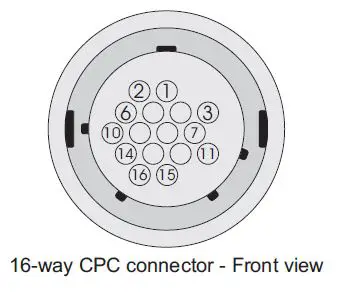
FTSPARK-8 (16-way CPC connector)
| 16-Way #Pin | Function |
| 1 | Multiplex from FT600 |
| 2 | Power Level |
| 3 | Can Low |
| 4 | Can Hi |
| 5 | Not Used |
| 6 | Not Used |
| 7 | Not Used |
| 8 | Power 12V + |
| 9 | Power 12V + |
| 10 | Power 12V + |
| 11 | Power 12V + |
| 12 | Signal GND |
| 13 | Power GND |
| 14 | Power GND |
| 15 | Power GND |
| 16 | Not Used |
Connectors
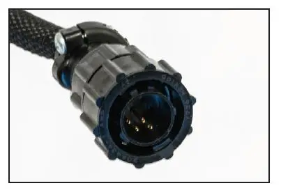
Firewall Circular Connector
The CPC connector is both safe and user-friendly and offers the perfect connection solution for the harness through the firewall, by having keys that don’t allow connection in the wrong position.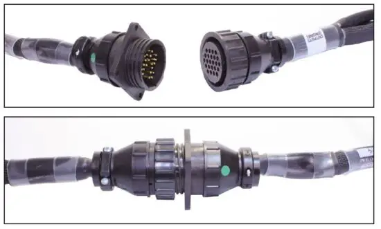
Relay and Fuses
All relays available in the PRO600 Harness are automotive sealed heavy duty type. The relay max current is 40A followed by a 40A fuse. There is a main relay for the FuelTech units such as ECU, O2 conditioner and sensors. The other relay is for the fuel injectors.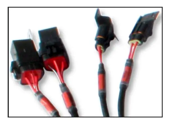
Crank Trigger and Cam Sync sensor
The harness is ready to run MSD 8276 and FT Hall Effect RPM/speed sensor (5005100083) for the crank trigger. For the cam sync sensor, it is designed to read the MSD 2346 cam sync kit and a hall effect sensor.
Crank Trigger
When using MSD 8276 as crank trigger, be sure that the violet wire from the sensor goes to the red wire of Crank VR connector and the green wire from the sensor goes to the black wire of Crank VR connector. If for any reason the sensor is not wired liked this, swap the wires to match and connect like the above. The Crank VR connector is a MSD 8824 and Crank Hall is a 3-way Metri-Pack 150.2.
| Sensor | Sensor pin/wire | Harness wire |
| FT Hall (5005100083) | A | 12V |
| B | White wire from Crack Hall | |
| C | Battery’s negative | |
| MSD 8276 | Purple | Red wire from Crank VR |
| Green | Black wire from Crank VR | |
| MSD 8154 | Red | Red wire from Crank VR |
| Black | Black wire from Crank VR | |
| Electrimotion | 1 | Black wire from Crank VR |
| 2 | Red wire from Crank VR |
Cam Sync sensor
The PRO600 is made to read the MSD 2346 Cam Sync kit and FT Hall Effect RPM/speed sensor (5005100083). With MSD 2346, the purple wire must go to the white wire from Cam VR and the green wire must go to the black wire from Cam VR. If for any reason the sensor is not wired like this, swap the wires to match and connect like above.
| Sensor | Sensor pin/wire | Harness wire |
| FT Hall (5005100083) | A | 12V |
| B | White wire from Crack Hall | |
| C | Battery’s negative | |
| MSD 2346 | Purple | Red wire from Cam VR |
| Green | Black wire from Cam VR | |
| Pro Mag 44 | Black/Orange | Red wire from Cam VR |
| Black/Purple | Black wire from Cam VR | |
| Electrimotion | 1 | Black wire from Cam VR |
| 2 | Red wire from Cam VR |
TPS
TPS is a potentiometer that informs the throttle position. FT600 can read almost any 0-5V TPS. The PRO600 harness uses a 3-way male Weather Pack connector.
- Pin A: signal ground;
- Pin B: signal output;
- Pin C: 5V supply.

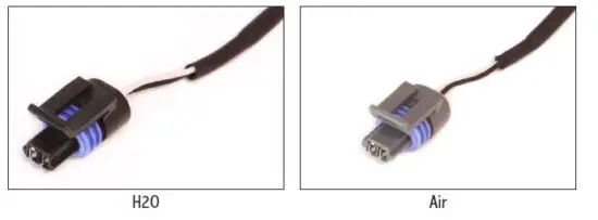
H2O and Air Temperature
The PRO600 Harness has 2 temperature inputs. One input is for the engine temperature (H2O) and the other is for the intake air temperature (AIR). Both sensors are GM style and uses Metri-Pack 150.2 connectors.
- Pin A: signal output;
- Pin B: battery’s negative.

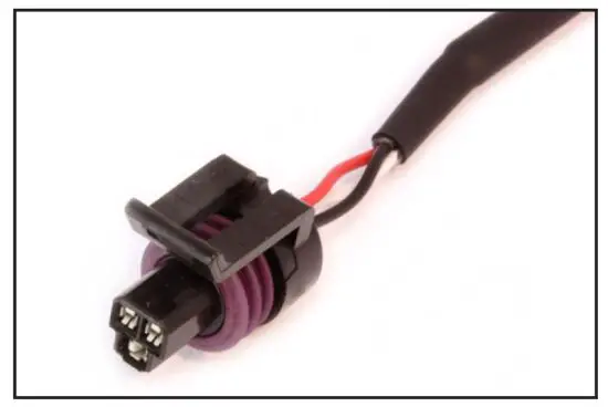
Oil, Fuel and Wastegate Pressure
The oil, fuel and Wastegate pressure sensor connectors are designed for the PS-150, PS-300 and PS-1500 sensors; ranging from 150 to 1500 psi, with a Packard style 3-way connector. It has a 5V ground and signal.
- Pin A: battery’s negative (black);
- Pin B: 5V supply (green/red);
- Pin C: signal output (white).

Injectors
There are 8 injector outputs available (primary bank). All injector connectors are Bosch EV1 style.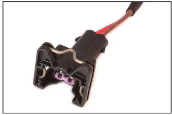
Back Pressure
This is a generic input pressure normally used to read back pressure. It can also be used as a MAP sensor input or any other 0-5V sensor. PRO600 harness comes with a Delphi MetriPack 150 connector and uses the white input #2, which is also available at Extra connector. When the back pressure connector is being used, the white #2 in the Extra connector can’t be used.
- Pin A: battery’s negative (black);
- pin B: 5V supply (green/red);
- Pin C: signal output (white).
NOTE:
Do not connect the pressure sensor directly to the exhaust manifold. Use a pipe between the sensor and the heat source to prevent overheat.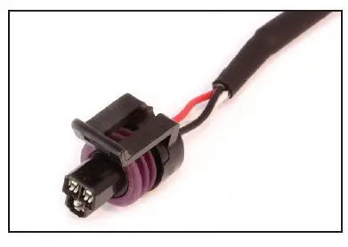
FuelTech EGT-8
EGT-8 connector to read Thermocouples Type K (sold separately), communicates with FuelTech over CAN A port.
- Pin 1: Switched +12V
- Pin 2: Sensor ground
- Pin 3: CAN A HI (+)
- Pin 4: CAN A LO (-)

POWERED CAN A
Auxiliary connectors in the Inner and Engine side of the harness that plug directly to the FuelTech Switch Panel or that can be used for something else. It has Switched 12V, sensor ground and CAN A communication.
- Pin 1: Switched +12V
- Pin 2: Sensor ground
- Pin 3: CAN A LO (-)
- Pin 4: CAN A HI (+)

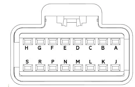
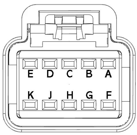
White – Inputs
| INPUTS – White | ||
| Pin | FT600 Extra White Input | Function/Sensor |
| A | White input #1 | |
| B | White input #3 | |
| C | White input #8 | |
| D | White input #9 | |
| E | White input #12 | |
| F | White input #13 | |
| G | White Input #14 | |
| H | White Input #15 | |
| J | White input #16 | |
| K | White input #17 | |
| L | White input #18 | |
| M | White input #19 | |
| N | White input #20 | |
| P | Green/Red 5V outputs for sensors | |
| R | Red – 12V input from relay | |
| S | Green/Black – Ground for Sensors | |
 | ||
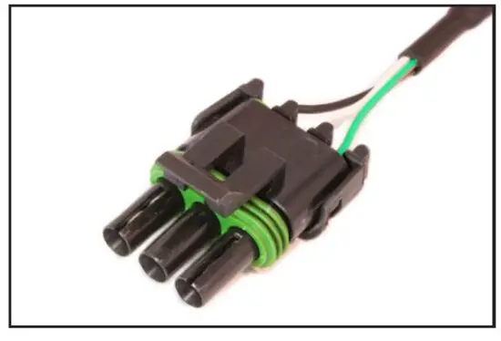
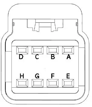
Yellow – Outputs
| OUTPUTS C – Yellow | ||
| Pin | FT600 Extra Yellow Outputs | Function/Sensor |
| A | Yellow output #1 | |
| B | Yellow output #2 | |
| C | Yellow output #3 | |
| D | Yellow output #4 | |
| E | Yellow output #5 | |
| F | Yellow output #6 | |
| G | Yellow output #7 | |
| H | Yellow output #8 | |
 | ||
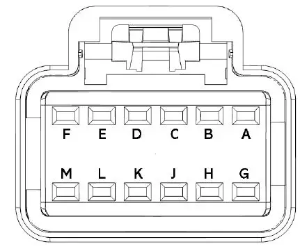
Blue – Outputs
| OUTPUTS A – Blue | ||
| Pin | FT600 Extra Blue Outputs | Function/Sensor |
| A | Blue output #9 | |
| B | Blue output #10 | |
| C | Blue output #11 | |
| D | Blue output #12 | |
| E | Blue output #13 | |
| F | Blue output #14 | |
| G | Blue output #15 | |
| H | Blue output #16 | |
| J | Red – 12V input from relay | |
| K | Black – negative battery | |
| L | NOT USED | |
| M | NOT USED | |
 | ||
Gray – Outputs
| OUTPUTS B – Grey | ||
| Pin | FT600 Extra Gray Outputs | Function/Sensor |
| A | Gray output #1 | |
| B | Gray output #2 | |
| C | Gray output #3 | |
| D | Gray output #4 | |
| E | Gray output #5 | |
| F | Gray output #6 | |
| G | Gray output #7 | |
| H | Gray output #8 | |
| J | Red – 12V input from relay | |
| K | Black – negative battery | |
|
| ||
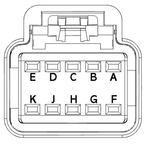
Gray – Outputs – FORD configuration
| OUTPUTS B – Grey | ||
| Pin | FT600 Extra Gray Outputs | Function/Sensor |
| A | Gray output #1 | Cylinder 5 |
| B | Gray output #2 | Cylinder 1 |
| C | Gray output #3 | Cylinder 6 |
| D | Gray output #4 | Cylinder 2 |
| E | Gray output #5 | Cylinder 7 |
| F | Gray output #6 | Cylinder 3 |
| G | Gray output #7 | Cylinder 8 |
| H | Gray output #8 | Cylinder 4 |
| J | Red | 12V input from relay |
| K | Black | Negative battery |
| ||
If the system being activated requires a 12v output, the yellow outputs are capable of ground or 12v. If no yellow outputs are available, it’s possible to drive a relay by ground with any gray output to get the proper 12v output switched by one of the gray outputs by following this diagram: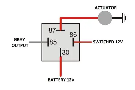
Yellow outputs are the most specialized outputs. They are HALF BRIDGE or PUSH PULL type outputs. This means that they can feed 5A both by negative or positive side. They are important and necessary to control Electronic drive-by-wire throttle (DC motors) and stepper motor 4 wire idle control valves. They also can be used to control any type of LO SIDE or HI SIDE actuator (LO SIDE means the ECU will switch ground to activate the device, HI SIDE means the ECU will switch 12V to active the device). Since it can feed 12V power at 5A, if wired to a relay activating it by ground (from the FuelTech) when turned off, it senses the 12V through the relay coil and feeds back power to the ECU. In this case, it is necessary to run a series diode (4004 or 4007) like the following schematic to avoid this issue. Both ways of wiring this output are described in the following diagrams: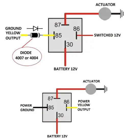
There are some relays with a built-in diode, like Hella 003437101.
Standard Sensors
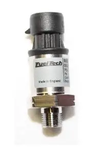
Fuel and Oil Pressure
FuelTech PS-150/300/1500 is a high precision sensor responsible for general pressure readings (fuel, oil, boost, exhaust back pressure, etc.) It can be purchased online at www.fueltech.net or from an authorized FuelTech dealer (check the website to locate the dealer nearest to you). FuelTech PS-150/300/1500 sensor below:
- Connection: 1/8” – 27NPT
- Pressure Range: 0 to 150/300/1500psi
- Power Voltage: 5V
- Output Scale: 0.5-4.5V
- Electric Connector: 3-way Metri Pack 150
- Pin 1: Battery’s Negative
- Pin 2: 5V supply
- Pin 3: Output signal

FuelTech part numbers:
- 5005100020 – 0-150 psi sensor
- 5005100021 – 0-300 psi sensor
- 5005100217 – 0-500 psi sensor
- 5005100022 – 0-1500 psi sensor
- 5005100220 – 0-3000 psi sensor
Intake Air Temperature
With this sensor, the ECU can monitor the intake air temperature and perform real time compensations. One of its pins is connected to the battery negative, the other to the white #7 wire.
Part numbers: FuelTech 5005100015 or GM 25036751
Engine Temperature
This sensor is very important for a good running engine, as varying engine temperatures dramatically affect an engine’s fuel and timing requirements. On water cooled engines, place this sensor near the engine head, reading the water temperature. On air cooled engines, install this sensor reading the engine oil temperature. One of its pins is connected to the battery negative, the other to the white #5 wire. Part numbers: FuelTech 5005100016 or GM 12146312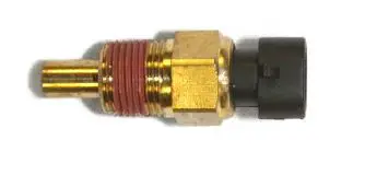
Meters and adapter wires
Fuel Tech WB-O2 Nano
The WB-02 Nano has a 12-way connector with 3 wire groups. One of them has the connector for the O2 sensor, the second makes the CAN communication with FT600 and the third is responsible for power and analog output. By default, the analog output is set to values of 8.7AFR to 16.2AFR Gas, but can be configured to 5.14AFR to 17.6AFR Gas or 9.55 to 19.11AFR or 9.55 to 58.80AFR or yet 9.55 to 146.9AFR (Gas), if necessary. For further information, check the FuelTech WB-O2 Nano manual.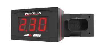
FuelTech EGT-8
The FuelTech EGT-8 is the module that is capable to read Thermocouple Type K sensors and send the data to the ECU through CAN A communication port. Capable to read temperatures from 32ºF to 1832ºF.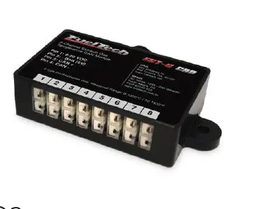
Alcohol O2
The FuelTech Alcohol O2 is a dual channel O2 reader and is designed to read extremely low AFRs, recommended mainly for alcohol engines in drag race application, since it is able to read down to 0.28 lambda (1.79AFR alcohol, 2.52AFR E100 or 4.12AFR gasoline). FuelTech Alcohol O2 has an AMP Super Seal connector. For further information, check the FuelTech Alcohol O2 manual.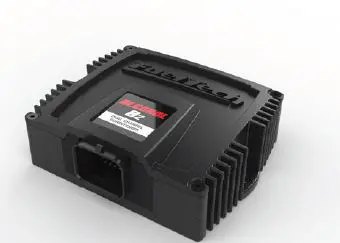
Bosch LSU 4.2 Wideband O2 Sensor
The BOSCH LSU 4.2 is a wideband O2 sensor that can be used with both the WB-O2 Nano and Alcohol O2. When using LSU 4.2 with our Alcohol O2 reader, an adapter harness is required, as well as free air calibration. Check the Alcohol O2 manual for further instructions.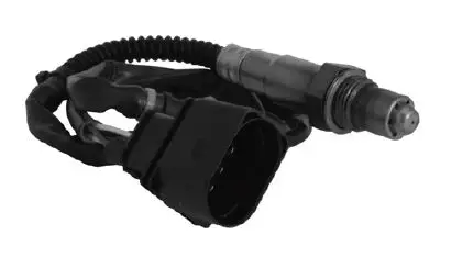
NTK WB-O2 sensor – Alcohol
The NTK wideband O2 sensor is designed for high accuracy and low AFR’s, must be used with FuelTech Alcohol O2. This sensor requires an adapter harness and free-air calibration. For further information, check the FuelTech Alcohol O2 manual.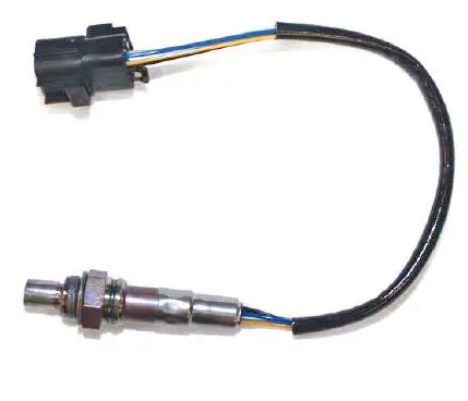
Bosch LSU 4.2 O2 sensor to Alcohol O2 adapter harness
This adapter is required when using the Alcohol O2 with Bosch LSU 4.2 O2 sensors. Each channel of the Alcohol O2 can read a single Bosch LSU 4.2 O2 sensor. To purchase the adapter harness, contact FuelTech. Part numbers: FuelTech 3022000965 or Bosch.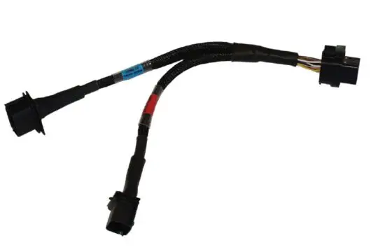
WB-O2 sensor Bosch to NTK adapter harness
This adapter is necessary to use 16 injectors with Alcohol O2. To purchase the adapter harness, contact FuelTech.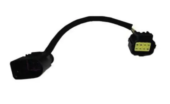
Peak and Hold – External Injector Driver
Peak and Hold drivers are designed to control the current on low impedance injectors. The FuelTech Peak and Hold has 4 outputs and in the PRO Wiring Harness will run one injector per channel.
There are 3 different versions of Peak and Hold available to fire different injectors, according to the resistance of the injector. The only differences between the versions are the peak current and the hold current. Considering one injector per channel application: 2A/0.5A – Bosch 1600cc, Ford Racing 1600cc 4A/1A – Siemens Deka 225lb/hr, Precision 225lb/hr 8A/2A – Precision 550lb/hr, Billet Atomizer, Moran Some earlier Moran injectors require a 4A/1A driver. Contact FuelTech tech support to confirm correct Peak and Hold drivers before purchasing. When using high impedance injectors without Peak and Hold drivers, jumpers wires (sold separately, part number 2001000071) must be connected to the Peak and Hold plugs in the harness. If the jumper wires are not being used then the injectors won’t fire since there will be no continuity between the FT600 and injectors.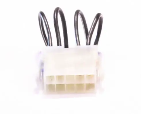
Troubleshooting
| Issue | Solution | |
|
FT600 Unit doesn’t turn on | 1. | Check battery voltage |
| 2. | Check power and ground cables | |
| 3. | Check Switched 12V cable | |
| 4. | Check ECU harness cables | |
| FT600 doesn’t read cranking | 1. | Check crank trigger and cam sync connections (chapter 7.3) |
| 2. | Check sensor gap | |
| 3. | Check diagnostic panel for RPM signal | |
|
FT600 reads RPM but engine doesn’t start | 1. | Check if there is spark and injector pulse |
| 2. | Check fuel pressure | |
| 3. | Check crank trigger alignment and TPS calibration | |
| 4. | Check if outputs are activated and properly configured | |
| 5. | Check the O2 sensor reading | |
|
Engine runs but doesn’t idle | 1. | Check TPS calibration |
| 2. | Check timing with a timing light | |
| 3. | Check TPS idle table and adjustment | |
| 4. | Check O2 sensor reading | |
| Engine spits & sputters | 1. | Check O2 sensor reading |
| 2. | Check ignition calibration and firing order | |
| ECU won’t communicate to PC | 1. | Ensure your software version is compatible with your FT600 firmware version |
| 2. | Check if read and write buttons get colored when FT600 is connected | |
FuelTech Latest Manuals and Software
You can access all updated manuals and software at the FuelTech website: www.fueltech.net/manuals www.fueltech.net/software


