![]()
![]()
X-ROM iQ
Instructions For Use
BEFORE USING THE DEVICE, PLEASE READ THE FOLLOWING INSTRUCTIONS COMPLETELY AND CAREFULLY. CORRECT APPLICATION IS VITAL TO THE PROPER FUNCTIONING OF THE DEVICE.
INTENDED USER PROFILE
The intended use should be a licensed medical professional, the patient, the patient’s caretaker, or a family member providing assistance. The user should be able to read, understand, and be physically able to perform and follow the directions, warnings, and cautions provided in the information for use. This device is not intended for use by children.
INTENDED USE/INDICATIONS
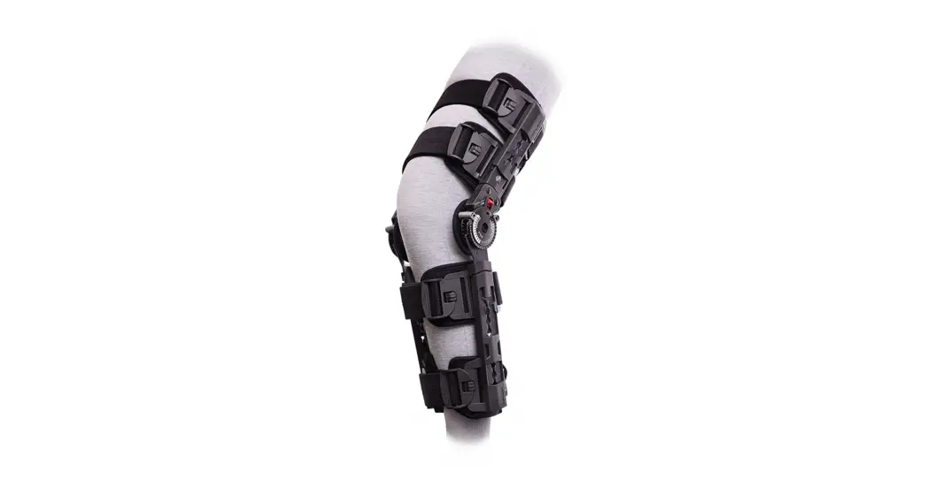
To aid in immobilization and protected range of motion associated with ACL, PCL, LCL, MCL surgeries, and meniscal repairs. This product was designed to help complement the variety of medical treatments common to the above afflictions. The range of motion settings, frequency, and duration of use should be determined by your prescribing Healthcare professional. The Motion iQ platform together with the X-ROM iQ brace is intended to be used to measure and evaluate activity and knee joint range of motion.
CONTRAINDICATIONS
None.
WARNINGS AND CAUTIONS
If you experience any pain, swelling, sensation changes, or any unusual reactions while using this product, consult your medical professional immediately. Do not wear brace while swimming, in the shower, or bath. Do not use this product outside of intended use.
Warning: Equipment contains a CR2032 lithium coin cell battery. There is a danger of explosion if lithium-ion batteries are incorrectly replaced.
SYMBOLS
 | WARNING! Read and understand all warnings and Instructions for Use before using this device. |  | Manufacturer |
| Temperature range |  | Non-ionizing electromagnetic radiation | |
 | Atmospheric pressure range | Humidity Range | |
 | Indication for protection against water and particular matter. |  | Prescription only (USA). |
ENVIRONMENTAL CONDITIONS
| operating conditions | Temperatures | +41°F (5°C) TO +104°F (40°C) |
| Relative Humidity | 15% to 90% non-condensing | |
| Atmospheric Pressure | 700 hPa to 1060 hPa | |
| Altitude | Maximum of 3000 m | |
| Transport and Storage Conditions | Temperatures | -13°F (-25°C ) without relative humidity control, up to 158°F (70°C) |
| Relative Humidity | 15% – 90% non-condensing | |
| Atmospheric Pressure | 500 hPa to 1060 hPa |
When operating after transporting or storage in elevated or low-temperature conditions, please keep the sensor at ambient temperature for 15 min. prior to operation.
APPLICATION SET UP AND PAIRING
- Download Motion iQ TM App from the App store.
- Ensure Bluetooth is enabled on your phone or tablet Settings
a. For iPhone: Settings > Bluetooth > On
b. For Android: Settings > Connections. Bluetooth > On - Follow the link in the welcome email from your clinician. This will launch the Motion iQ application and start your account setup. (Note: If you have not yet received a welcome email, please contact your physician)
- Follow the instruction in the application to complete your account setup.
- Follow the instructions in the application to pair with your mobile phone or tablet.
a. When prompted by the app to choose a brace to pair, select X-ROM iQ
b. Watch the pairing instruction video in the application
c. On the brace hinge marked with “iQ”, use a small object such as a pen or paper clip to press the button until the blue LED light blinks (see image 1 below)
d. Click “Go” when prompted in the app on your mobile phone or tablet
e. Screen will show “Congratulations” when successfully connected.
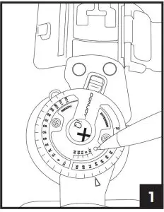
Note: This step only needs to occur one time. Brace will pair automatically while wearing the brace and standing in full extension.
BRACE APPLICATION INFORMATION
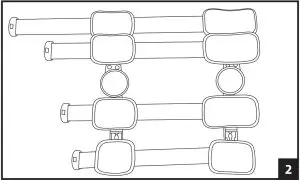
- Unfasten strap ends near black buckles and open brace flat by pulling both uprights apart.

- Place the leg on top of the flat brace. A shorter upright is applied to the thigh. Adjust brace until each upright is aligned to the centerline of the medial and lateral sides of the leg and the center of the hinge is aligned with the center of the knee joint.

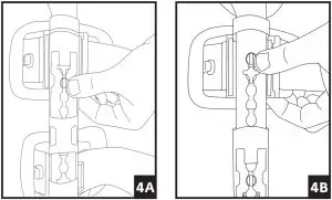
- Telescope sliders by depressing the slider button until the desired length is reached. The top and bottom sliders should be adjusted first, followed by the sliders closest to the knee (note that inner sliders cannot be adjusted until the outer sliders are moved to provide sufficient clearance). Ensure that both bars are equal in length and that each strap slider is indexed to the same position on each upright respectively.
 4. Adjust the strap lengths:
– Ensure the tab is lifted from the strap, allowing the strap to move freely (see arrow position A in figure 5)
– By pulling the strap away from the body, remove slack from the backside of the brace (see arrow position B in figure 5)
– Ensure uprights are aligned on medial and lateral sides of the leg
– Lower tab and apply pressure to secure strap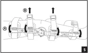
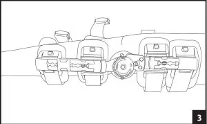
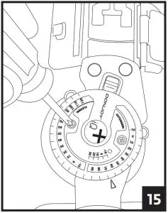
5. Attach each of the black buckles. Tighten straps by pulling on the loose ends. Remove the excess strap and reposition alligator strap end to the new edge of the strap. Secure strap-end to strap.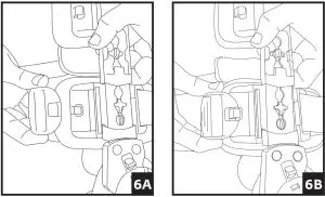 6. A) Adjust the hinge by pulling the Flexion and Extension stops outward and rotating until the desired angle aligns with the button center. Release stops and ensures they are fully inserted.
B) Utilize the quick-lock feature at -10, 0, 10, 20, or 30 degrees, by aligning the red arrow with the desired degree and sliding the red quick lock button inward until the lock is engaged. Ensure uprights do not rotate. If another lock setting is required, see step 6 and ensure both Flexion and Extension buttons are set at the same angle setting.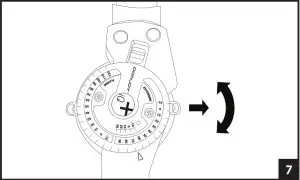 7. To remove the brace, release each buckle. The brace can then be reapplied as a single unit.
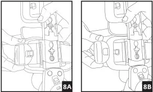
OTHER ADJUSTMENTS: The hinge bars may be bent to add varus or valgus contouring. Bend each bar by holding the thigh/calf bar firmly against a solid surface and apply gentle and constant pressure to the hinge in the direction desired. Bend each side bar an equal amount above and below the hinge. For optimal ease of application post-operatively, pre-fit the brace prior to surgery if possible.
STRAP REPLACEMENT: Should straps require replacement, carefully use scissors to cut away the strap where it connects to the slider. Insert the new strap and secure. contact JO for the X-ROM iQ Replacement Straps Kit. If you are having any medical issues or need an urgent response, please call your doctor’s office directly.
If assistance is needed with the brace or setting up or using the App, please call or email:
Phone: (844) 279-0200
Email: [email protected]
Visit: DJOglobal.com
![]() Hand wash foam liners in water (30°C) with mild detergent. Rinse thoroughly. AIR DRY only, do not heat dry.
Hand wash foam liners in water (30°C) with mild detergent. Rinse thoroughly. AIR DRY only, do not heat dry.
 Do not wash the hinge component containing the electronic sensor.
MATERIAL CONTENTS
Nylon 50%, Aluminum 40%, Polypropylene 5%, Delrin 3%, Stainless Steel 2%.
BATTERY REPLACEMENT
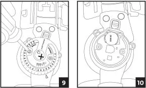
1. Locate the hinge with the iQ logo. Using a Phillips head screwdriver, unscrew the two screws and remove the hinge cover.
2. Using a fingernail or small object such as a ball point pen, push the gold battery clip to the side and lift up the battery to remove.
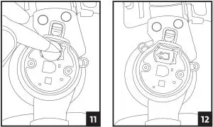
3. Place the new battery into the slot towards the gold clip then push the opposite side down until the battery clicks into place.
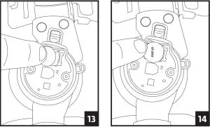
4. Carefully slide the hinge cover back onto the brace and secure it by replacing the screws. Be careful to not over-tighten the screws.
FCC AND IC STATEMENTS
FCC Statements
Warning: Changes or modifications to this device not expressly approved by (DJO LLC) could void the user’s authority to operate the equipment.
NOTE: This equipment has been tested and found to comply with the limits for a Class B digital device, pursuant to Part 15 of the FCC Rules. These limits are designed to provide reasonable protection against harmful interference in a residential installation. This equipment generates, uses, and can radiate radio frequency energy and, if not installed and used in accordance with the instructions, may cause harmful interference to radio communications. However, there is no guarantee that interference will not occur in a particular installation. If this equipment does cause harmful interference to radio or television reception, which can be determined by turning the equipment off and on, the user is encouraged to try to correct the interference by one or more of the following measures:
- Reorient or relocate the receiving antenna.
- Increase the separation between the equipment and receiver.
- Connect the equipment into an outlet on a circuit different from that to which the receiver is connected.
- Consult the dealer or an experienced radio/TV technician for help.
This equipment complies with radiation exposure limits set forth for an uncontrolled environment. This equipment is in direct contact with the body of the user under normal operating conditions. This transmitter must not be co-located or operating in conjunction with any other antenna or transmitter. This device complies with Part 15 of the FCC Rules. Operation is subject to the following two conditions: (1) This device may not cause harmful interference, and (2) this device must accept any interference received, including interference that may cause undesired operation.
IC Statements
This device complies with Industry Canada licence-exempt RSS standard(s). Operation is subject to the following two conditions: (1) this device may not cause interference, and (2) this device must accept any interference, including interference that may cause undesired operation of the device.
ELECTROMAGNETIC COMPATIBILITY (EMC)
The X-ROM iQ sensor is intended for use in the electromagnetic environment specified below. The customer or user of the X-ROM iQ sensor should assure that it is used in such an environment.
Guidance and Manufacturer’s Declaration – Electromagnetic Emissions | ||
| Emissions Tests | Compliance | Electromagnetic Environment Guidance |
| RF Emissions CISPR 11 | Group 1 | The X-ROM iQ sensor is an equipment where there is intentionally generated, or used, conductively coupled Radio Frequency (RF) energy that is necessary for the internal functioning of the equipment |
| RF Emissions CISPR 11 | Class B | The X-ROM iQ sensor is suitable for use in all establishments, including domestic establishments and those directly connected to public low voltage power supply network that supplies buildings used for domestic purposes. |
| Harmonic Emissions IEC 61000-3-2 | N/A. Battery Powered. | N/A |
| Voltage Fluctuations/ emission oscillations IEC 61000-3-3 | N/A. Battery Powered. | N/A |
Guidance and Manufacturer’s Declaration – Electromagnetic Immunity | |||
| Immunity Test | IEC 60601 Test Level | Compliance Level | Electromagnetic Environment Guidance |
| Electrostatic Discharge (ESD) IEC 61000-4-2 | ±6 kV contact ±8 kV air | ±8 kV contact ±15 kV air | Floors should be wood, concrete or ceramic tile. If floors are covered with synthetic material, the relative humidity should be at least 30%. |
| Electrical Fast Transient/ Burst IEC 61000-4-4 | ±2 kV for power supply lines ±1 kV for input/ output lines | N/A. Battery Powered. | The main power quality should be that of a typical commercial or hospital environment. |
| Surge IEC 61000-4-5 | ±1 kV differential mode ±2 kV common mode | N/A. Battery Powered. | The main power quality should be that of a typical commercial or hospital environment. |
| Voltage dips, short interruptions, and voltage variations on power supply input lines IEC 61000-4-11 | <5% U (>95% dip in TU) for 0.5 cycle 40% U (60% dip in TU) for 5 cycles 70% U (30% dip in TU) for 25 cycles <5% U (>95% dip in TU) for 5 sec | N/A. Battery Powered. | The main power quality should be that of a typical commercial or hospital environment. |
| Power Frequency (50/60Hz) Magnetic Fields IEC 61000-4-8 | 3 A/m | 30 A/m | Power frequency magnetic fields should be at levels characteristic of a typical location in a typical commercial or hospital environment. |
Guidance and Manufacturer’s Declaration – Electromagnetic Immunity | |||
| Portable and mobile RF communications equipment should be used no closer to any part of the X-ROM iQ sensor, including cables, than the recommended separation distance calculated from the equation applicable to the frequency of the transmitter. | |||
| Immunity Test | IEC 60601 Test Level | Compliance Level | Recommended Separation Distance |
| Conducted RF IEC 61000-4-6 | 3 Vrms 150 kHz to 80 MHz | 3 V | 1.2√P |
| Radiated RF IEC 61000-4-3 | 3 V/m 80 MHz to 2.5 GHz | 10 V/m | 0.35√P 80 MHZ TO 800 MHZ 0.7√P 800 MHZ TO 2.5 GHZ |
| Where P is the maximum output power rating of the transmitter in watts (W) according to the transmitter manufacturer and d is the recommended separation distance in meters (m). Field strengths from fixed RF transmitters, as determined by an electromagnetic site survey a, should be less than the compliance level in each frequency range b. Interference may occur in the vicinity of equipment marked with the following symbol:
| |||
| NOTE 1: At 80 MHz and 800 MHz, the higher frequency range applies NOTE 2: These guidelines may not apply in all situations. Electromagnetic propagation is affected by absorption and reflection from structures, objects, and people | |||
aField strengths from fixed transmitters, such as base stations for radio (cellular/ cordless) telephones and land mobile radios, amateur radio, AM and FM radio broadcast and TV broadcast cannot be predicted theoretically with accuracy. To assess the electromagnetic environment due to fixed RF transmitters, an electromagnetic site survey should be considered. If the measured field strength in the location in which the X-ROM iQ sensor is used exceeds the applicable RF compliance level above, the X-ROM iQ sensor should be observed to verify normal operation. If abnormal performance is observed, additional measures may be necessary, such as reorienting or relocating the X-ROM iQ sensor. bOver the frequency range 150 kHz to 80 MHz, field strengths should be less than 3 V/m.
TECHNICAL SPECIFICATIONS
Recommended Separation Distances between Portable and Mobile RF Communications Equipment and the X-ROM iQ sensor
The X-ROM iQ sensor is intended for use in an electromagnetic environment in which radiated RF disturbances are controlled. The customer or the user of the X-ROM iQ sensor can help prevent electromagnetic interference by maintaining a minimum distance between portable and mobile RF communications equipment (transmitters) and the X- ROM iQ sensor as recommended below, according to the maximum output power of the communications equipment.
| The rated maximum output power of the transmitter (watts) | Separation distance according to the frequency of the transmitter (Meters) | ||
| 150 KHz to 80 MHz d = 1.2 VP | 80 MHz to 800 MHz d = 0.35 VP | 800 MHz to 2.5 Glitz d = 0.7 VP | |
| 0.01 | 0.12 | 0.03 | 0.07 |
| 0.1 | 0.38 | 0.11 | 0.22 |
| 1 | 1.2 | 0.35 | 0.7 |
| 10 | 3.8 | 1.1 | 2.2 |
| 100 | 12 | 3.5 | 7 |
For transmitters rated at a maximum output power not listed above, the recommended separation distance d in meters (m) can be estimated using the equation applicable to the frequency of the transmitter, where P is the maximum output power rating of the transmitter in watts (W) according to the transmitter manufacturer.
NOTE 1: At 80 MHz and 800 MHz, the separation distance for the higher frequency range applies.
NOTE 2: These guidelines may not apply in all situations. Electromagnetic propagation is affected by absorption and reflection from structures, objects, and people.
WARRANTY
DJO, LLC will repair or replace all or part of the unit and its accessories for material or workmanship defects for a period of six months from the date of sale. To this extent, the terms of this warranty are inconsistent with local regulations. The provisions of such local regulations will apply.
DISPOSAL
The sensor is electronic equipment and may include substances that can damage the environment. Do not dispose of the device in municipal waste. Do not puncture. Do not dispose in fire or incinerate. Dispose of the unit according to national, state, and local regulations.
Rx ONLY.
INTENDED FOR SINGLE PATIENT USE.
NOT MADE WITH NATURAL RUBBER LATEX.
NOTICE: WHILE EVERY EFFORT HAS BEEN MADE IN STATE-OF-THE-ART TECHNIQUES TO OBTAIN THE MAXIMUM COMPATIBILITY OF UNCTION, STRENGTH, DURABILITY, AND COMFORT, THERE IS NO GUARANTEE THAT INJURY WILL BE PREVENTED THROUGH THE USE OF THIS PRODUCT. THIS DEVICE IS NOT INTENDED TO PREVENT INJURY, BUT AS AN ADJUNCT TO POSTOPERATIVE THERAPY. USE CAUTION AND FOLLOW YOUR DOCTOR’S ADVICE.
![]()
![]() DJO, LLC
DJO, LLC
1430 Decision Street
Vista, CA 92081-8553 • the USA
T +1.800.321.9549
T +1.800.336.6569
F +1.800.936.6569
DJOglobal.com
©2021 DJO, LLC. All rights reserved.
14-4014 REV B
2021/02/16


