![]() TW TRACETM Vertical
TW TRACETM Vertical
Installation Instructions
Profiles:
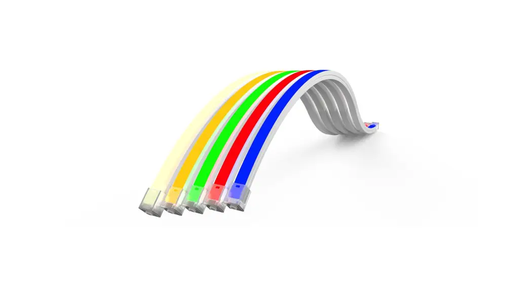
TRACE™ Vertical
TW TRACE Vertical
TRACETM is an indoor/outdoor low voltage lighting system used primarily for direct or indirect lighting designs.
Please verify the contents of the packages!
Please read instructions entirely before starting installation
Be sure power is turned off before installing the system
Call Tivoli, LLC tech support with questions
Caution: TRACETM TW is designed to work with listed Class 2 24V DC transformers only. Use of any other power source will cause damage, shorten the life of the fixture and will void the warranty.
Consult any and all applicable local and national codes for installation.
Do not conceal or extend exposed conductors through a building wall as per local electrical code.
Warning: With any luminaire for any application, basic safety precautions should always be followed to reduce the risk of fire, electric shock and personal injuries. This lighting system should be installed by a certified professional.
![]()
WARNINGS
TRACETM TW MAY BE EASILY DAMAGED! The reliability of the product can only be ensured if these warnings and cautions are complied with faithfully. Keep these instructions for future maintenance work.
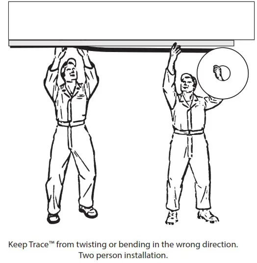
WARNING! Risk of product damage. Longer runs of TraceTM lighting strands must be installed by at least two people.
IMPORTANT! The TraceTM Tunable White luminaire must not be allowed to bend or hang down. That way, the bending limit will not be inadvertently exceeded, resulting in product damage.
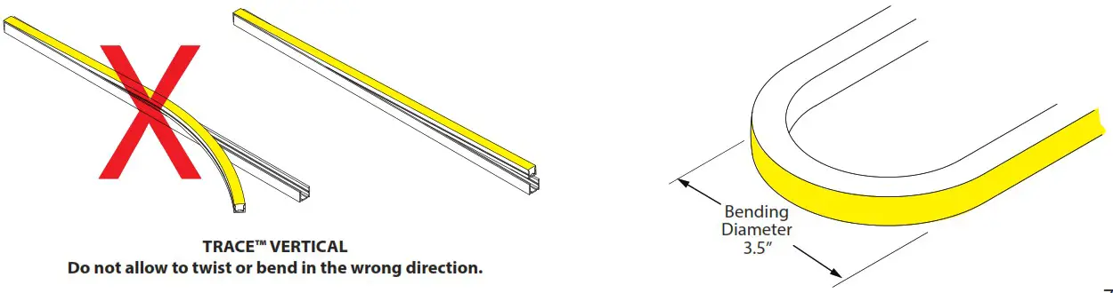
Warning! Risk of product damage.
TraceTM TW Vertical must not be bent at less than 3.5″ diameter or damage will result. Do not allow TraceTM to twist or bend in the wrong direction.
WARNING! Risk of Damage. Insert TraceTM TW Vertical into channel evenly and gradually to keep twisting and bending to a minimum.
Overview: Read Before Installing Luminaire
Installation Notes:
Step 1: Measure run area where TraceTM is to be installed. Locate power feed end at highest point of the run to minimize exposure to water run off.
Step 2: A Mounting Channel is recommended for outdoor applications. Lay channel along desired area and attach with screws (by others) every 18 to 24 inches. If the design requires creating bends and arcs, it is recommended that the Vertical Notched Channels are used. Mounting Clips are for use on indoor applications only.
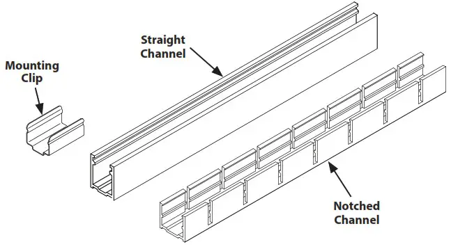
Note: Minimum bending diameter for the notched channel is 11″. TraceTM lighting strand must not be bent at less than 3.5″ diameter or damage will result.
Step 3: TraceTM must be installed with two people. One to press the luminaire into the channel and the other to hold the spool and unroll it while keeping the TraceTM flex body straight.
Warning: Risk of Product damage. Do not stretch, pull, or yank. Doing so can damage the TraceTM internal connections and void the warranty.
Step 4: Insert TraceTM into mounted channel starting from power connector end. The End Cap and Power Feed Connector do not fit within the channel, so cut the Mounting Channel so that connectors and End Caps will overhang outside the ends of the Channel. TraceTM should be pressed into the channel carefully and gradually, without excessive bending or damage will result.
Note: We recommend using a dry spray lubricant, such as 3M Spray Lubricant or WD-40 Specialist for all TraceTM installations to insure the luminaire fits into the channel without damage. Additionally, when installing with Mounting Clips, Silicone Sealant (FLXD-SIL-GE-10) may be applied to the inside bottom surface.
Step 5: Secure power connection to building with use of C-clamp (by others) or mount connection inside J-Box.
Connect to 24V DC power supply according to supplied wiring diagrams.
TraceTM Tunable White Mounting Options
TraceTM Tunable White Vertical with Mounting Clips
Warning: Risk of Product Damage. Only bend the TraceTM Vertical so the lens bends up or down. See diagram below.
Note: Minimum bending diameter for TraceTM TW Vertical is 3.5″ in the vertical direction only.
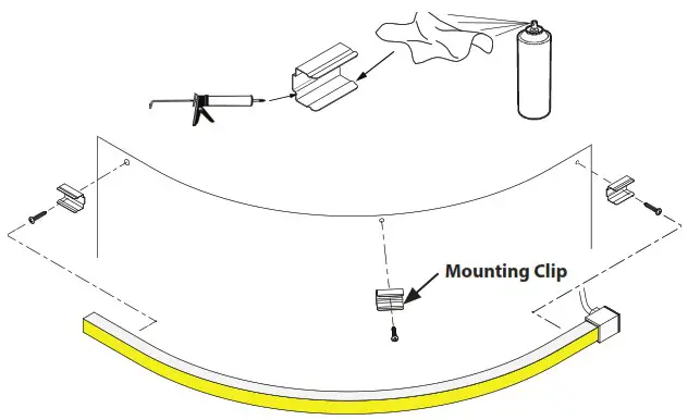
Step 1: Determine where the Mounting Clips will need to be installed to achieve the desired shape.
Step 2: Position the Mounting Clips and attach with screws (Included).
Step 3: Lay a bead of Silicone Adhesive (LFXD-SIL-GE-10) to the inside bottom surfaces of the Mounting Clips, as shown.
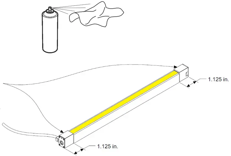
Step 4: Spray Dry Lubricant on a rag and wipe the inside upper surfaces of the mounting clips, as shown, to allow the TraceTM fixture to slide more easily into the mounting clip. 3M Spray Lubricant or WD-40 Specialist is recommended.
Warning! Risk of Product Damage.
Regular WD40 490002 will stress craze, crack or swell the TraceTM Silicone covering. Do not use!
Step 5: TraceTM must be installed with two people. One to press the luminaire into the channel and the other to hold the spool and unroll it while keeping the TraceTM flex body straight.
Step 6: Press the TraceTM into the Mounting Clips.
Step 7: Connect to power.
Bending Limitations
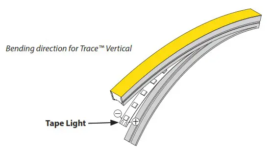
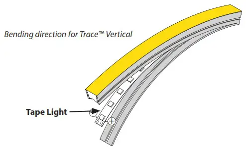
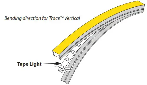
Warning! Risk of Product Damage. TraceTM TW Vertical can only be bent in the direction that does not twist the Tape Light.
Install TraceTM TW Vertical in Notched Mounting Channel
Warning: Risk of Product Damage. Only bend the TraceTM Vertical so the lens bends up or down so as not to twist the Tape Light. See diagrams.
Note: Minimum bending diameter for the notched channel is 11″. However, the minimum bending diameter for Trace Vertical is 3.5″ in the vertical direction only.
Step 1: Determine Channel mounting Location.
Step 2: Drill a hole 3″ from each end of the Channel and 18″-24″ along length of Channel.
Step 3: Position the Notched Channel and attach with screws (Included).
 Step 4: Spray dry lubricant on a rag and wipe along the inside upper surfaces of the extrusion. We recommend using a dry spray lubricant, such as 3M Spray Lubricant or WD-40 Specialist for all TraceTM installations to insure the luminaire fits into the channel without damage.
Step 5: TraceTM must be installed with two people. One to press the luminaire into the channel and the other to hold the spool and unroll it while keeping the TraceTM flex body straight.
Step 6: Start by orienting the TraceTM with the Lens facing away from the Channel, as shown.
Step 7: Insert the TraceTM body into the Channel one flex section at a time. Start at one end and and press it down carefully and gradually, working along the Channel, inserting the TraceTM body into each section until the entire TraceTM fixture is securely mounted in the channel.
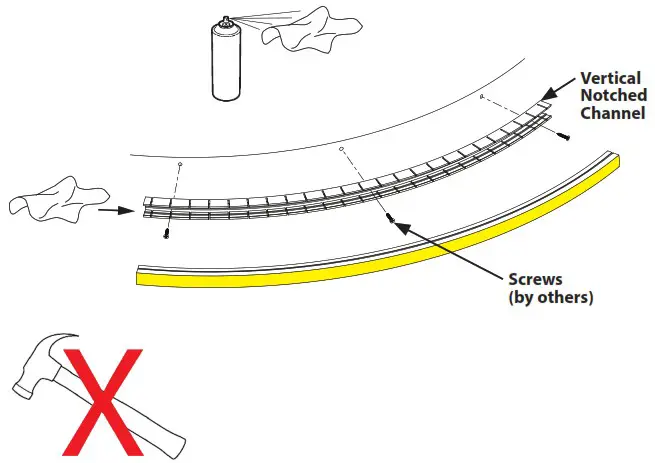
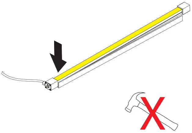
WARNING! Risk of Product Damage.
Do not hammer or pound the luminaire into the channel. Once inserted, do not pull or yank on the fixture. TraceTM will be damaged unless it is handled carefully.
Step 8: Connect to power.
Bending Limitations
Warning! Risk of Product Damage. TraceTM TW Vertical can only be bent in the direction that does not twist the Tape Light.
Straight Channel for TraceTM TW Vertical Installation
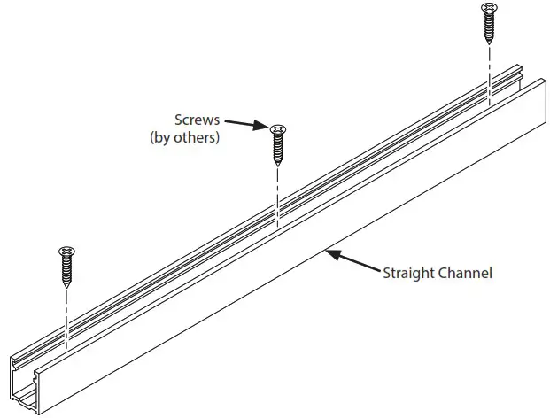
Step 1: Prepare Straight Mounting Channel for installation cutting it to the correct length, keeping in mind that the End Caps will not fit inside the Channel, and by drilling screw holes 3″ from each end and additional holes approximately every 18″ along the channel.
Step 2: Place Straight Channel on the mounting surface and mark the hole locations.
Step 3: Remove the Channel and drill pilot holes at all hole locations.
Step 4: Place the Channel into position and secure with screws (not included).
Note: Screws (by others) should be appropriate for the mounting location. (ie: wood screws for wood, etc.)
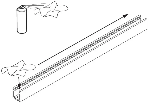
 Step 5: Spray dry lubricant on a rag and wipe along the inside upper surfaces of the extrusion. We recommend using a dry spray lubricant, such as 3M Spray Lubricant or WD-40 Specialist for all TraceTM installations to insure the luminaire fits into the channel without damage.
Step 6: TraceTM must be installed with two people. One to press the luminaire into the channel and the other to hold the spool and unroll it while keeping the TraceTM flex body straight.
tep 7: Start by orienting the TraceTM with the Lens facing away from the Channel, as shown.
 Step8: IMPORTANT! Insert the TraceTM body into the Channel. Start at one end and and press it down carefully and gradually, working along the Channel, inserting the TraceTM body along the channel until the entire TraceTM fixture is securely mounted in the channel.
 WARNING! Risk of Product Damage. Do not hammer or pound the luminaire into the channel. Once inserted, do not pull or yank on the fixture. TraceTM will be damaged unless it is handled carefully.
Step 9: Connect to power.
Bending Limitations
Warning! Risk of Product Damage.
TraceTM TW Vertical can only be bent in the direction that does not twist the Tape Light.
Bending direction for TraceTM Vertical
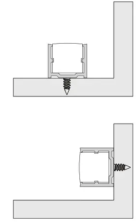
Note: TraceTM Mounting Channel can be mounted on horizontal or vertical surfaces.
Product Specification Guide
| LUMINAIRE | POWER CONSUMPTION | MAX RUN LENGTH* |
| Trace TW, Low Output | 1.5W | 58’ |
| Trace TW, Standard | 3W | 29’ |
| Trace TW, High Output | 4.5W | 19’ |
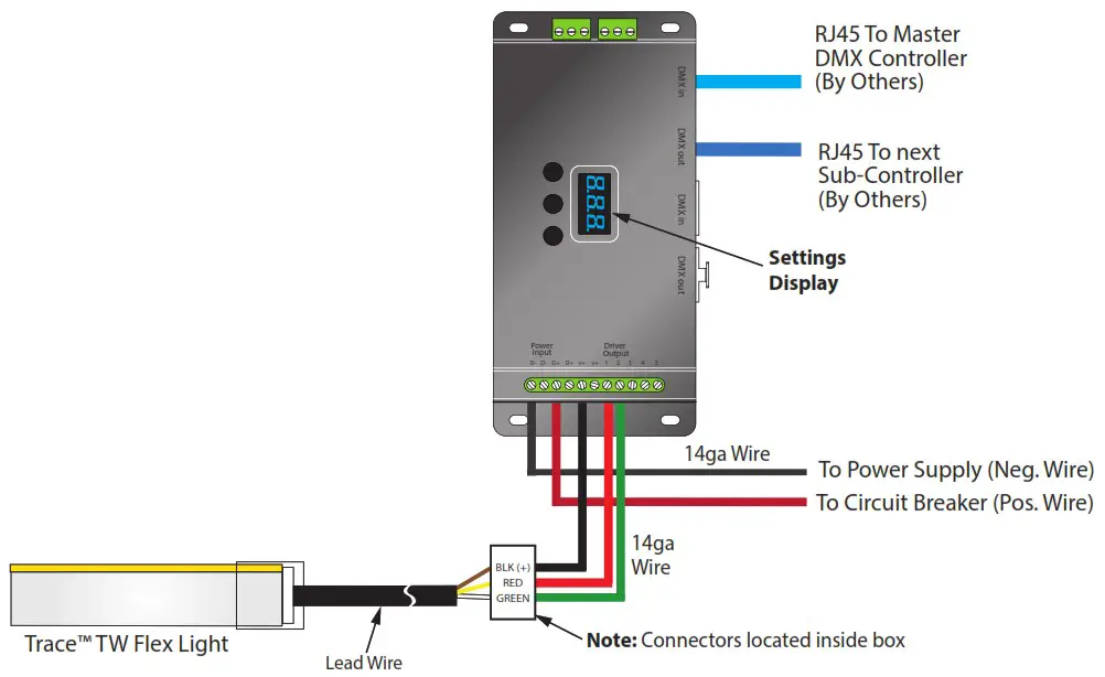
TraceTM Tunable White Basic Wiring Diagram
Elecrical Connections for TraceTM Tunable White
Step 1: Turn power off before beginning electrical installation.
Note: Contacting hot wires against the TraceTM leads may damage the product and void the warranty.
Step 2: Connect TraceTM lead wires to RGB-Sub-Controller, or if using our ADUL-DIN series transformers, connect to pre-wired connectors which are found inside the power supply box. Refer to diagram below and on Page. Make sure each lead wire is connected to the correct terminal, as follows:
| LEAD WIRE COLOR | SUB-CONTROLLER TERMINAL OR ADUL-DIN CONNECTOR WIRE COLOR |
| Brown | Black (+) |
| Yellow | Red |
| White | Green |
Step 3: Connect to a listed Class 2, 24V DC transformer only. See list of approved transformers.
Step 4: Optionally, TraceTM VW may be dimmed using an MLV or ELV dimmer that is suitable for the power supply. Please contact our technical support staff for more information.
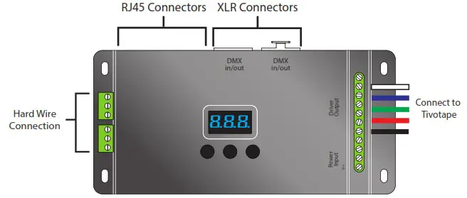
- DMX512 RDM decoder, RDM function can provide the interface between DMX master and decoder.
- OLED Display for example, DMX decoder’s address may be set from DMX master console.
- Multiple kinds of DMX in/out ports: RJ 45, XLR , normal screws.
- Total 5 PWM output channels, common anode. DMX channel quantity from 1CH~5CH programmable
- PWM output resolution ratio 8bit , 16bit settable.
- Output dimming curve gamma value from 0.1 ~ 9.9 settable.
- Programmable Decoding mode.
Safety and Warnings:
- Do not install with power applied to device.
- Do not expose to moisture.
Note: The Installation Instructions for your power supply includes DMX programming instructions.
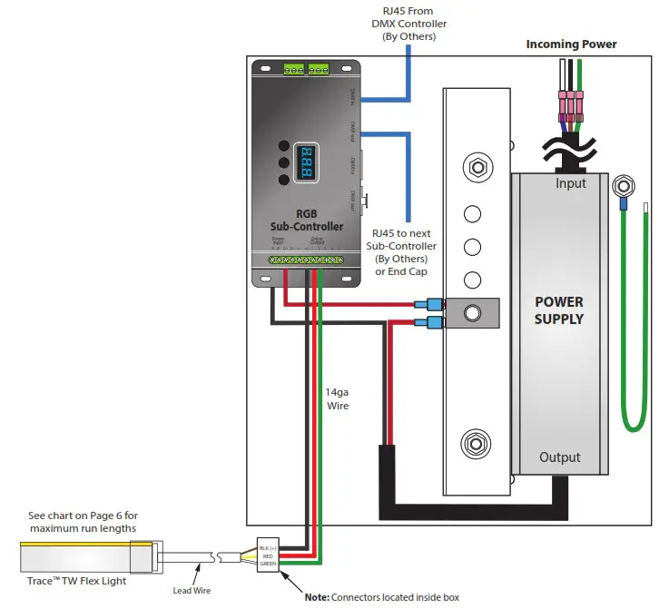
Power Supply with Sub-Controller Sample Wiring Diagram
There are many possible options for dimming TraceTM TW. See the specification Sheet for more information. The following wiring diagram is for reference only. Please refer to the Installation Instruction for the Power Supply you choose for detailed wiring instructions.
Copyright © 2022 Tivoli 08.08.22
www.tivolilighting.com
tel: 714-957-6101 fax:
714-427-3458


