BOSS Acoustic Simulator AC-3 Owner’s Manual
Before using this unit, carefully read the sections entitled: “USING THE UNIT SAFELY” and “IMPORTANT NOTES” (supplied on a separate sheet). After reading, keep the document(s) where it will be available for immediate reference.
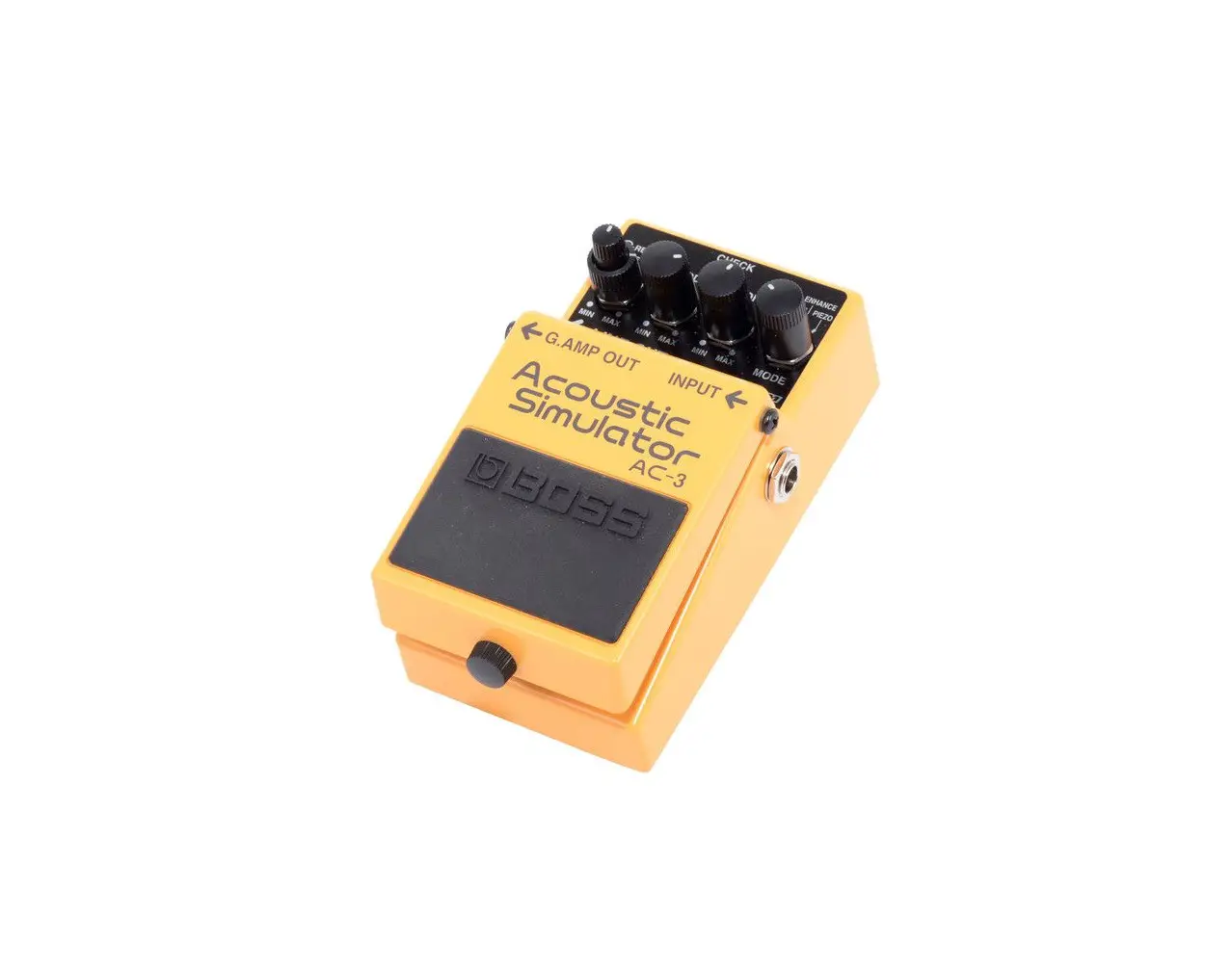
Panel Descriptions
| Name | Explanation | |
| 1 | DC IN jack | Accepts connection of an AC Adaptor (PSA series; sold separately). By using an AC Adaptor, you can play without being concerned about how much battery power you have left. We recommend that you keep batteries installed in the unit even though you’ll be powering it with the AC adaptor. That way, you’ll be able to continue a performance even if the cord of the AC adaptor gets accidently disconnected from the unit. Use only the specified AC adaptor (PSA-series). If the AC adaptor is connected while power is on, the power supply is drawn from the AC adaptor. |
| 2 | CHECK indicator | This indicator shows whether an effect is ON/OFF, and doubles as the Battery Check indicator. The indicator lights when an effect is ON. If this indicator goes dim or no longer lights while an effect is ON, the battery is near exhaustion and should be replaced immediately. &“Changing the Battery” |
| 3 | LINE OUT jack | This output jack is used for connecting to mixers, recorders, and other devices that accept line-level input. When a cable is also connected to the G.AMP OUT jack, the effect sound is output from the LINE OUT jack when the effect is switched on, while the output is muted when the effect is switched off. &“Connections” |
| 4 | G.AMP OUT jack | This output jack is used for connecting to guitar amps and other effects processors. The effect sound or direct sound is output from here depending on whether the effect is switched on or off. When a cable is simultaneously connected to the LINE OUT jack, the output from the G.AMP OUT jack is muted when the effect is switched on, while the direct sound is output when the effect is switched off. &“Connections” | ||
| 5 | INPUT jack | This jack accepts input signals (coming from an electric guitar, some other musical instrument, or another effects unit). * The INPUT jack doubles as power switch. Power to the unit is turned on when you plug into the INPUT jack; the power is turned off when the cable is unplugged. When not using the effects unit, be sure to disconnect the plug from the INPUT jack. | ||
| 6 | Pedal switch | This switch turns the effects on/off. | ||
| 7 | Thumbscrew | When this screw is loosened, the pedal will open, allowing you to change the battery. &“Changing the Battery” | ||
| 8 | [REVERB] knob | Adjusts the amount of reverb applied to the sound. | ||
| 9 | [LEVEL] knob | Adjusts the volume of the effect sound. | ||
| 10 | [BODY] knob | Adjusts the resonance of the sound produced by the guitar body, altering the characteristic mellowness and breadth of the acoustic guitar sound. | ||
| 11 | [TOP] knob | Adjusts the sense of attack and the harmonic content of the upper range. * If the sound is distorted, adjust by turning the [TOP] knob to the left (counterclockwise). * Distortion can also be suppressed by turning the [LEVEL] knob to the left. | ||
| 12 | [MODE] knob | Provides for selection of the tone. The knob can be used to select any of four tones. STANDARD This tone is that of the popular Dreadnought acoustic guitar body style. JUMBO This setting provides a tone characteristic of an oversized guitar body, a tone featuring a rich bass response along with a beautiful high end. Providing a sharper attack than the standard tone, this tone does not ENHANCE become masked by the sounds of other instruments, even in bands and ensembles. PIEZO This setting provides the tone of a round-back acoustic guitar, with subdued body resonance and a unique attack. | ||
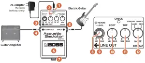
Connections
When Connecting to a Guitar Amp
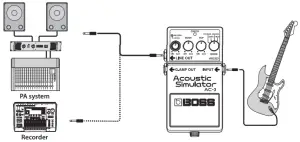
When Connecting to a PA System, Recorder, or Similar Equipment
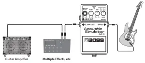
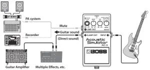
When Connecting Both to a Guitar Amp and PA System (or Recorder or Similar Equipment)
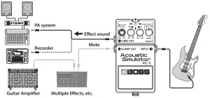
With Effect On: The CHECK indicator lights, the output from the AC-3: G.AMP OUT jack is muted, and the effect sound is output from the LINE OUT jack.
With Effect Off
The CHECK indicator is off, the guitar sound (with effect off) is output from the AC-3: G.AMP OUT jack, and the output from the LINE OUT jack is muted.
The following shows the correspondence between output jack connection status and the sound output.
| Output from LINE OUT | Output from G.AMP OUT | |||
| Effects On | Effects Off | |||
| Only G.AMP OUT Connected | – | – | Effect Sound (for Guitar Amp) | Direct Sound |
| Only LINE OUT Connected | Effect Sound (Line) | Direct Sound | – | – |
| Both LINE OUT and G.AMP OUT Connected | Effect Sound (Line) | Mute | Mute | Direct Sound |
Precautions When Connecting
- To prevent malfunction and equipment failure, always turn down thevolume, and turn off all the units before making any connections.
- Once the connections have been completed, turn on power to your various devices in the order specified. By turning on devices in the wrong order, you risk causing malfunction and/or damage to speakers and other devices. When powering up: Turn on the power to your guitar amp last.
When powering down: Turn off the power to your guitar amp first. - Before turning the unit on/off, always be sure to turn the volume down. Even with the volume turned down, you might hear some sound when switching the unit on/off. However, this is normal and does not indicate a malfunction.
Changing the Battery
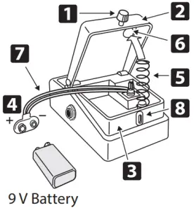
- Hold down the pedal and loosen the thumbscrew 1, then open the pedal 2 upward.
The pedal can be opened without detaching the thumbscrew completely. - Remove the old battery from the battery housing 3 , and remove the battery 4 snap connected to it.
- Connect the battery snap to the new battery, and place the battery inside the battery housing.
Be sure to carefully observe the battery’s polarity (+ versus -). - Slip the coil spring 5 onto the spring base 6 on the back of the pedal, and then close the pedal.
Carefully avoid getting the battery snap cord 7 caught in the pedal, coil spring, and battery housing. - Insert the thumbscrew into the guide bush hole 8 and tighten it securely.
Main Specifications
| Nominal Input Level | -20 dBu |
| Input Impedance | 1 MO |
| Nominal Output Level | -20 dBu |
| Output Impedance | 1 k.0 |
| Recommended Load Impedance | 10 k.0 or greater |
| Power Supply | Alkaline battery (9 V, 6LR61) AC adaptor (PSA series: sold separately) |
| Current Draw | 50 mA ‘1 Expected battery life under continuous use: Alkaline: 8 hours These figures will vary depending on the actual conditions of use. |
| Dimensions | 73 (W) x 129 (D) x 59 (H) mm 2-7/8 (W) x 5-1/8 (D) x 2-3/8 (H) inches |
| Weight | 425 g /15 oz (including Battery) |
| Accessories | Owner’s Manual Leaflet (“USING THE UNIT SAFELY,””IMPORTANT NOTES,”and “Information”) Alkaline battery (9 V, 6LR61) |
| Options (sold separately) | AC adaptor: PSA series |
0 dBu = 0.775 Vrms
This document explains the specifications of the product at the time that the
document was issued. For the latest information, refer to the Roland website.
Use of Battery
- The battery that was supplied with the unit is for temporary use, intended primarily for testing the unit’s operation. We suggest replacing this with an alkaline dry cell.
- If you handle batteries improperly, you risk explosion and fluid leakage. Make sure that you carefully observe all of the items related to batteries that are listed in “USING THE UNIT SAFELY” and “IMPORTANT NOTES” (supplied on a separate sheet).


