![]()
![]() VAVSMOD2
VAVSMOD2
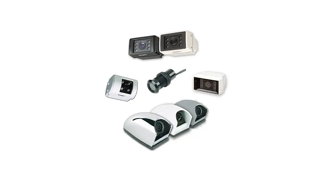
Voyager 360 Camera System
User Manual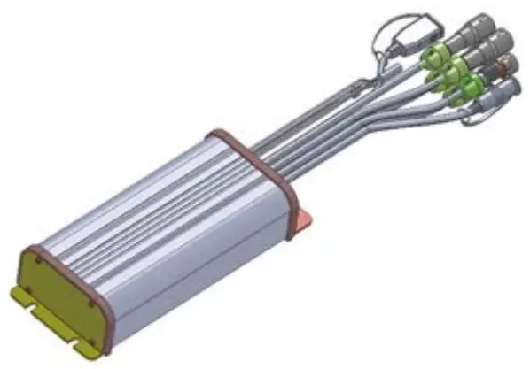 Version 1.2
Content List
| Item | Description | QTY |
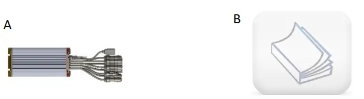
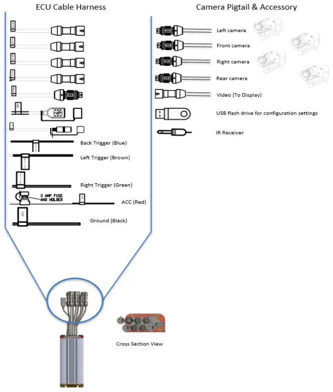
| A | ECU (electronic control unit/module) with Harness | 1 |
| B | User Manual | 1 |
Additional Products Required (Sold Separately)
Compatible Camera
| Item | Part Number | Description | QTY |
| C | VAVSCAM2 | Camera and camera hardware | 1 |
*NOTE: 4x VAVSCAM2 required for full system
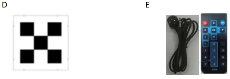
Calibration Tools
System Connections
Camera Installation and Calibration Layout with Small Mat
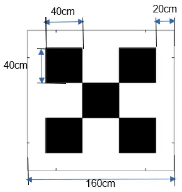
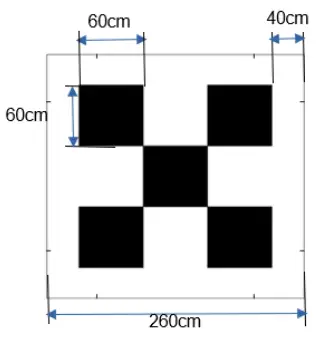
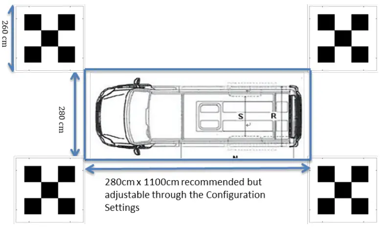
4.1 Mat Dimension
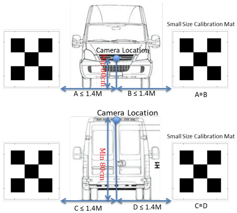
 4.2 Camera Installation Front and Rear View
The camera is recommended to be mounted at the center (A≅B, C≅D ), and the tolerance between C and D could be as much as +/- 30 cm if the Camera is mounted on the Roof.
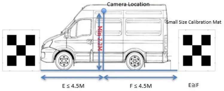
4.3 Camera Installation Side View
The camera is recommended to be mounted at the center (E≅F), and the tolerance could be as much as +/- 30 cm.
4.4 Calibration Layout Top View
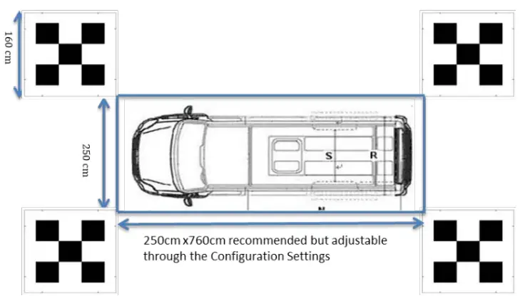
Camera Installation and Calibration Layout with Large Mat
5.1 Mat Dimension
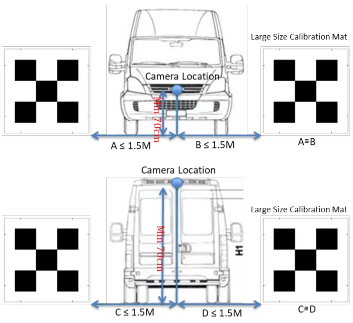
5.2 Camera Installation Front and Rear View
The camera is recommended to be mounted at the center (A≅B, C≅D ), and the tolerance between C and D could be as much as +/- 30 cm if the Camera is mounted on the Roof.
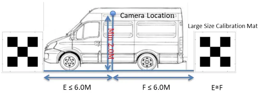
5.3 Camera installation Side View
The camera is recommended to be mounted at the center (E≅F), and the tolerance could be as much as +/- 30 cm.
5.4 Calibration Layout Top View
Auto Calibration
- Plug the IR receiver into the connecter labeled IR of ECU
- If a new calibration layout, new SKU, or new Vehicle Image deployment is needed, plug the USB Disk into the connector labeled USB of ECU,
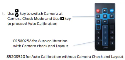
- Use the Remote Control to process the Auto/ Manual Calibration
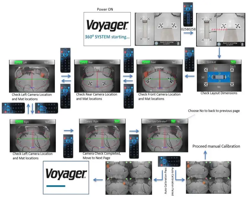
- Press 02580258 on the Remote Control for Auto Calibration with Camera Check View.
NOTE: As each button is pressed, you should see a red asterisk (*) appear on the screen indicating the button press was received by the ECU module. Once eight asterisks (********) are shown on the screen, the unit will enter the calibration process.
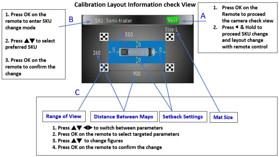
- Calibration Layout Information Check View

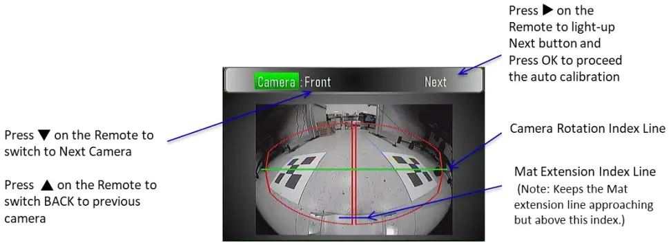
- Camera Check View
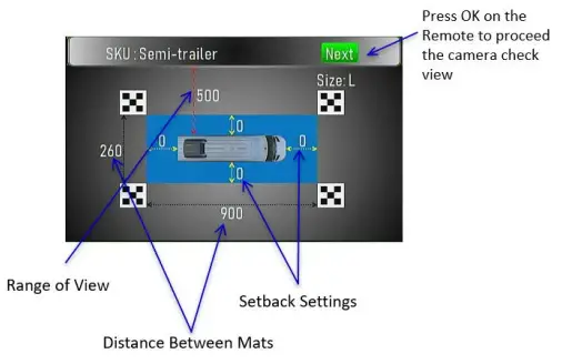
6.1 SKU, Layout, and Mat Selection
- In Calibration Layout Information Check View, press◄ the key and hold to proceed with SKU, Layout, and Mat size selection with remote control
- Move the cursor to SKU and press OK to enter SKU change mode
– Press ▲▼ to select the preferred SKU
– Press OK to confirm the change - Move the cursor to the target parameter and press OK to enter the parameter change mode
– Available parameters are Range of View/ Distance between mats/ Setback setting/ Mat size
– Press ▲▼ to select a preferred value
– Press OK to confirm the change - Move the cursor to NEXT and press OK to proceed with the camera check view
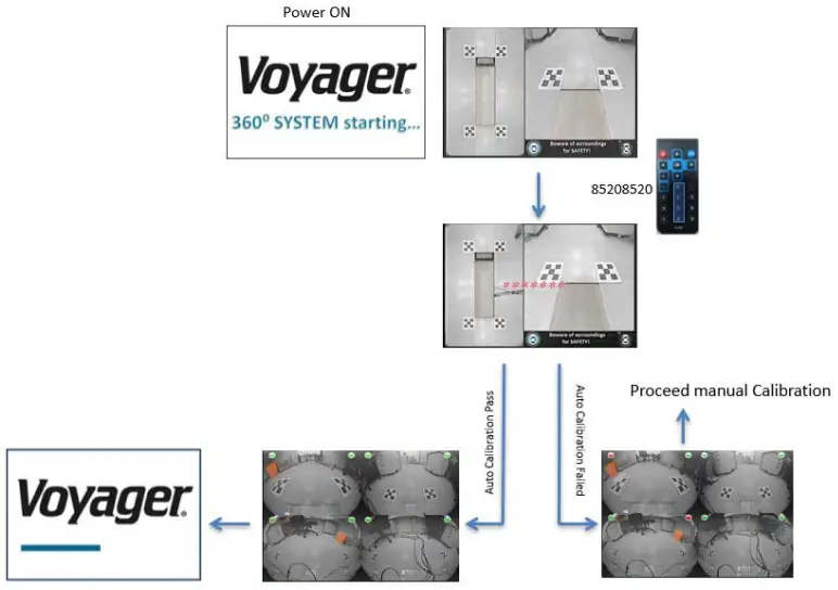
6.2 Auto Calibration Flow
- Press 02580258 on the Remote to access Auto-calibration with Layout/Camera Check View

- Press 85208520 on the Remote to access Auto-calibration without Layout/Camera Check

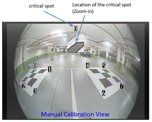
Manual Calibration
When the system failed to complete the auto calibration, it will lead to manual calibration.
(However, it is recommended to find the obstruction which caused the failure and remove it from the layout area. Then reattempt the auto-calibration process.)
Manual Calibration Process:
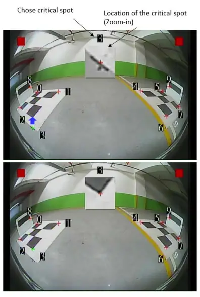
- Use the numerical keys (0-7) on the remote to choose the critical spot which is NOT in the correct location.
- Use the cursor (▲▼◄►) to move the critical spot to the correct location and check the zoom-in window to confirm.
- Use “MENU” key to switch cameras and inner/outer critical spot views
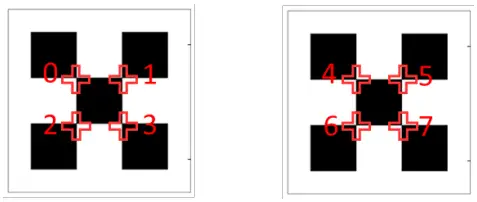
The Correct Locations of each outer critical spot
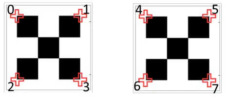 The Correct Locations of each inner critical spot
7.1 Manual Calibration Flow
- Use the numerical keys on the remote to choose the critical spot which is NOT in the correct location. (in this case #3)
- Use the Remote cursor (▲▼◄►) to move the cursor to the correct location. (The Zoom-in window at the top helps with accuracy)
- Once finished with the adjustments, Press the “MENU” key to switch to the inner 8 critical spots of the same camera and repeat the adjustment, if needed.
- When step 3 is finished, the Remote the “MENU” key to switch to the next camera and repeat steps 1, 2, and 3.
- When all four cameras are checked (Front -> Rear-> Left-> Right -> Front), Press “OK” to complete manual calibration setup. The system will reset and process the calibration.
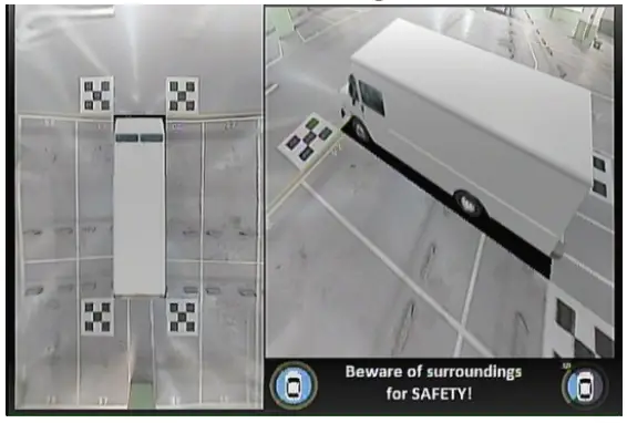
Trigger Views
If the vehicle is driving forward without turn signals triggered, the VAVSMOD2 will give the driver a top view and Rear view
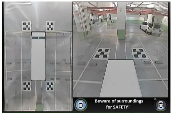
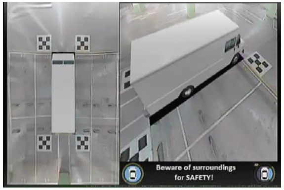
If the Left Turn Signal is triggered, the VAVSMOD2 will give the driver a top view and left-side view
If the Right Turn Signal is triggered, the VAVSMOD2 will give the driver a top view and a Right-side view
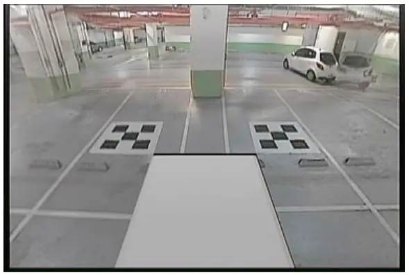
If the vehicle gear is set to Reverse, the VAVSMOD2 will give the driver a full-screen Rear view
Note: Reverse trigger has the top priority. Whenever the turn light and backward are both triggered, the VAVSMOD2 shows the backward view.
Specification
| VAVSMOD2 ECU | |
| Power Supply | DC 12V |
| Power Consumption | 700 mA (Max) |
| Working Temp | -40 ℃ ~ +85 ℃ |
| Storage Temp | -40 ℃ ~ +95 ℃ |
| Input Signal | AHD 720P |
| Video Input | Camera * 4 |
| Video Output | CVBS/NTSC (640 * 480 Pixel) |
| IR port | 1 |
| USB port | 1 |
| VAVSCAM2 CAMERA (SOLD SEPARATELY) | |
| Image Sensor | 1/3“ (SONY) |
| Resolution | 1.2M |
| Optical Lens | 2G4P + IR Cut |
| Aperture | 2.0 |
| FOV | 190° (H)/ 140° (V) |
| Optical Decenter | 5 Pixel |
| Operating Temperature | -20°C ~ 70°C |
| Min Illumination | 0.1 Lux |
| Power Supply | DC 12V |
| Water Resistance | IP67 |
Trouble Shooting Guide
| Issue | Possible Causes | Corrective Actions |
| No power | Bad connection of power input | Please check AVM power and ground connection |
| No image on the screen | Monitor signal cable is not connected | Please check if the monitor signal cable is properly connected or if any pins inside the connector are bent |
| The fuzzy screen on the monitor | Dirt on the surface of the lenses | Please clean the lenses with soft and clean fabric |
| The screen image is not clear | Monitor display resolution is too low | Resolution with 480X234 above is recommended |
| The dark image on the screen | Camera video cable of the camera is not connected to the VAVSMOD2 ECU module | Please check if the camera video cable is connected or if any pins inside the connector are bent |
| Camera is damaged | Please replace the camera (may require re-calibration) | |
| No function of left/right/reverse trigger | The trigger signal is not properly connected | Please check if the trigger signal is connected |
| The system will not auto- calibrate | The calibration Mat is obstructed | Check for objects obstructing the camera view of the Mats. Fold in side mirrors if they are obstructing. |
| Calibration Mats are not within the Red Box | Perform calibration camera check (press 02580258 on the remote). Check that the Mats are within the red box AND above the blue Mat Extension Index Line. | |
| Poor lighting or Shadows on the calibration Mats | Check for poor lighting conditions or shadows that are being cast onto the calibration Mats. Correct the poor light condition. |
Version 1.2
July 26, 2021


