![]()
User Guide
Symbio 700 Controller
![]() SAFETY WARNING
SAFETY WARNING
Only qualified personnel should install and service the equipment. The installation, starting up and servicing of heating, ventilating, and air-conditioning equipment can be hazardous and requires specific knowledge and training. Improperly installed, adjusted, or altered equipment by an unqualified person could result in death or serious injury. When working on the equipment, observe all precautions in the literature and on the tags, stickers, and labels that are attached to the equipment.
Introduction
Read this manual thoroughly before operating or servicing this unit.
Warnings, Cautions, and Notices
Safety advisories appear throughout this manual as required. Your personal safety and the proper operation of this machine depend upon the strict observance of these precautions.
The three types of advisories are defined as follows:![]() WARNINGIndicates a potentially hazardous situation that, if not avoided, could result in death or serious injury.
WARNINGIndicates a potentially hazardous situation that, if not avoided, could result in death or serious injury.![]() CAUTIONIndicates a potentially hazardous situation that, if not avoided, could result in minor or moderate injury. It could also be used to alert against unsafe practices.
CAUTIONIndicates a potentially hazardous situation that, if not avoided, could result in minor or moderate injury. It could also be used to alert against unsafe practices.
NOTICEIndicates a situation that could result in equipment or property damage only accidents.![]() WARNING
WARNING
Proper Field Wiring and Grounding Required! Failure to follow code could result in death or serious injury. All field wiring MUST be performed by qualified personnel. Improperly installed and grounded field-wiring poses FIRE and ELECTROCUTION hazards. To avoid these hazards, you MUST follow requirements for field wiring installation and grounding as described in NEC and your local/state/national electrical codes.![]() WARNING
WARNING
Personal Protective Equipment (PPE) Required! Failure to wear proper PPE for the job being undertaken could result in death or serious injury. Technicians, in order to protect themselves from potential electrical, mechanical, and chemical hazards, MUST follow precautions in this manual and on the tags, stickers, and labels, as well as the instructions below:
• Before installing/servicing this unit, technicians MUST put on all PPE required for the work being undertaken (Examples; cut resistant gloves/sleeves, butyl gloves, safety glasses, hard hat/bump cap, fall protection, electrical PPE, and arc flash clothing). ALWAYS refer to appropriate Safety Data Sheets (SDS) and OSHA guidelines for proper PPE.
• When working with or around hazardous chemicals, ALWAYS refer to the appropriate SDS and OSHA/GHS (Global Harmonized System of Classification and Labelling of Chemicals) guidelines for information on allowable personal exposure levels, proper respiratory protection, and handling instructions.
• If there is a risk of energized electrical contact, arc, or flash, technicians MUST put on all PPE in accordance with OSHA, NFPA 70E, or other country-specific requirements for arc flash protection, PRIOR to servicing the unit. NEVER PERFORM ANY SWITCHING, DISCONNECTING, OR VOLTAGE TESTING WITHOUT PROPER ELECTRICAL PPE AND ARC FLASH CLOTHING. ENSURE ELECTRICAL METERS AND EQUIPMENT ARE PROPERLY RATED FOR INTENDED VOLTAGE.![]() WARNING
WARNING
Follow EHS Policies! Failure to follow the instructions below could result in death or serious injury.
• All Trane personnel must follow the company’s Environmental, Health, and Safety (EHS) policies when performing work such as hot work, electrical, fall protection, lockout/Tagout, refrigerant handling, etc. Where local regulations are more stringent than these policies, those regulations supersede these policies.
• Non-Trane personnel should always follow local regulations.
Copyright
This document and the information in it are the property of Trane, and may not be used or reproduced in whole or in part without written permission. Trane reserves the right to revise this publication at any time and to make changes to its content without the obligation to notify any person of such revision or change.
Trademarks
All trademarks referenced in this document are the trademarks of their respective owners. The Symbio™ 700 controller is a factory-installed, programmed control system providing digital control and protection of the equipment. It offers equipment and control configurations that can be used with Odyssey™ cooling and heat pump systems. This control system consists of the Symbio™ 700 main controller and up to four option modules used to provide optional functional operation. A system may or may not include optional modules, depending on the configuration of the equipment.
Applications
Odyssey cooling and heat pump split systems
Features and Benefits
• Open and Flexible
– Readily available software for configuration and troubleshooting
– Field upgradable software
– Built on mobile service technology, Symbio 700 empowers customers to select a service that meets their needs
– Full suite of communication options for BAS integration today and into the future
– Optional TGP2 and XM support (Tracer TU required) to provide custom sequences and/or side control functionality
• Connected
– Optional remote access and monitoring, providing troubleshooting support without a site visit.
Controller Overview
The Symbio 700 has two model options:
• SSttaannddaarrdd CCoonnffiigguurraattiioonn — provides standard troubleshooting via an on-board user interface (UI) and access to the Symbio Service and Installation mobile app.
• AAddvvaanncceedd CCoonnffiigguurraattiioonn — introduces additional troubleshooting tools and Building Automation System interface via BACnet® (ANSI/ASHRAE Standard 135-2016) or LonTalk™.
To upgrade from Standard Functionality to Advance Functionality a new Symbio 700 controller must be purchased with the Advance Functionality and installed on the equipment.
Functionality
| Feature | Standard Functionality | Advanced Functionality |
| Event Log | Only show last 5 through Mobile Service Tool Unavailable on Onboard UI | Unrestricted on Mobile Service Tool Unavailable on Onboard UI |
| Active Alarms | Most Current with Highest Priority through Mobile Service Tool Unrestricted with Onboard UI | Unrestricted |
| Export Trends | Not Allowed on Mobile Service Tool Not Allowed on Onboard UI | Unrestricted on Mobile Service Tool |
| Communication Protocol | None | BACnet MS/TP BACnet Air-Fi BACnet IP LonTalk |
| TGP2 | None | Unrestricted |
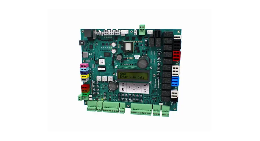
User Interface
The Symbio 700 controller provides a 2 X 16 backlit LCD display in the middle of the controller. The onboard user interface includes a Bluetooth pair button to pair with the Symbio 700 controller for use with the mobile service tool.
Figure 1. User interface keypad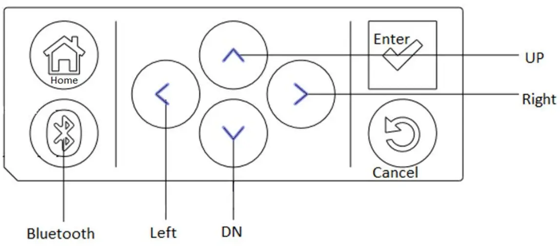
Table 1. User interface buttons
| Button | Description |
| Up/down | Allow the user to scroll the menus and submenus. |
| Left/right | Allow the user to scroll between values for editable items. |
 | • Allows users to drill down into a component of the menu tree. • Confirm data changes on writable data. When data is editable, the data point’s least significant digit flashes with a cursor. If the data has multiple editable digits, the user scrolls the cursor left and right to choose the editable digit. Once the editing is complete, the data is not changed and propagated through the controller until the Enter button is tapped. |
 | Tap to exit all submenus and return to the Home screen. |
 | Tap to go to the Bluetooth menu and initiate the Bluetooth device pairing sequence. |
 | Tap to return to the previous menu level. |
Figure 2. Symbio 700 menu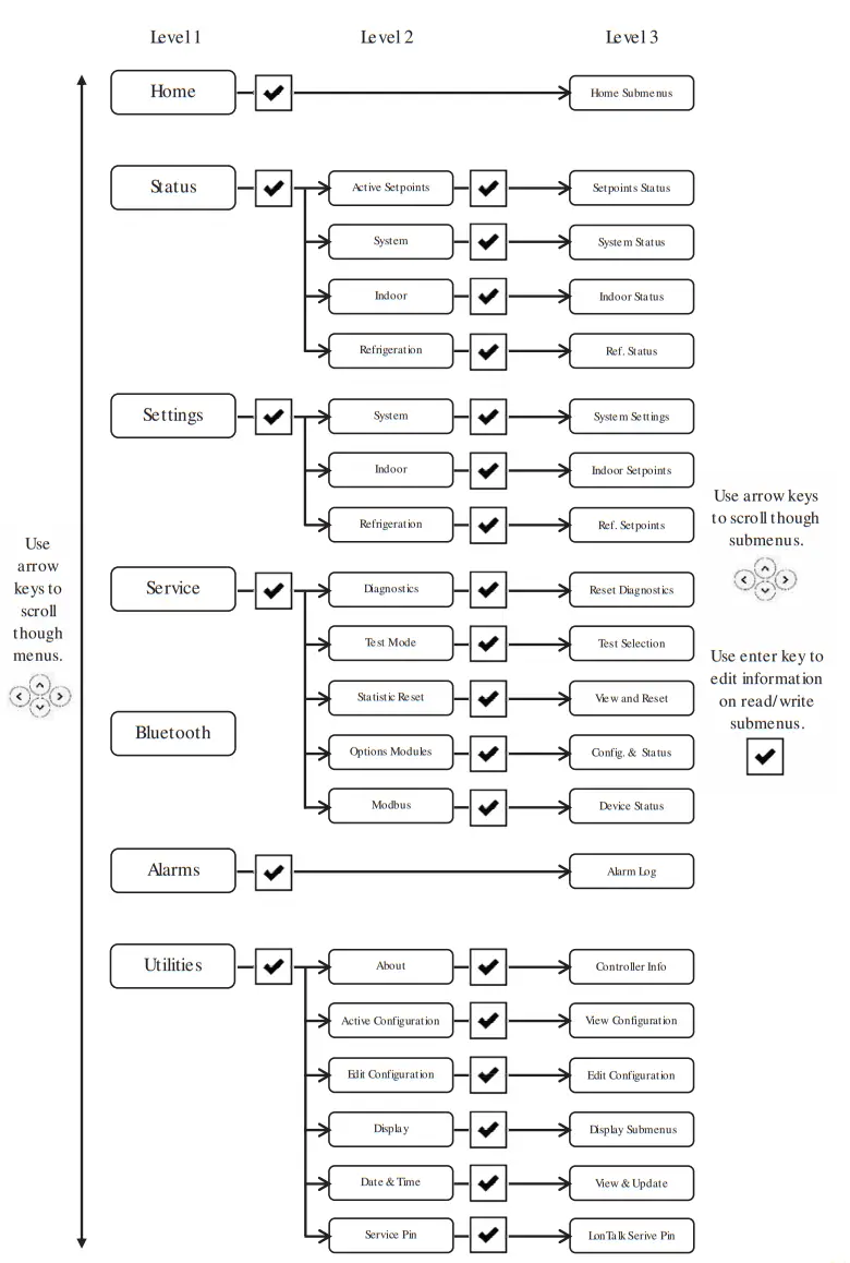
Menu | Description | |
| Home | Allows the user to view the status of: | |
| Unit Operation | ||
| Status | Active Setpoints | Allows the user to view all active setpoint values |
| System | Allows the user to view the status of: | |
| Alarm indicator | ||
| Equipment shutdown input | ||
| Phase Monitor | ||
| Supply Air Tempering (if configured) | ||
| T-Stat Inputs | ||
|
Indoor | Allows the user to view the status of (if configured): | |
| Supply fan information | ||
| Indoor Symbio Options Module | ||
| Discharge Air Temperature | ||
| Filter Runtime Hours | ||
| Refrigeration | Allows the user to view the status of: | |
| Compressor Information and Setpoints | ||
| Refrigeration Circuit Information | ||
| Settings | System | Allows the user to change them: |
| Arbitration Method Request | ||
| Emergency Override BAS | ||
| Unit Stop Command | ||
| Indoor | Allows the user to change the (if configured): | |
| Supply Fan Information | ||
| Filter Runtime Hours | ||
| Refrigeration | Allows the user to change the: | |
| Compressor Information | ||
| Refrigeration Circuit Information | ||
| Service | Diagnostics | Allows the user to reset active diagnostics. |
| Test | Allows the user to set the unit into service test using the Service Test Request. | |
| Statistic Reset | Allows the user to reset all the component statistic data. | |
| Options Modules | Displays configuration, communication status, and firmware versions of option modules. | |
| Modbus | Displays communication status of Modbus devices. | |
| Bluetooth | Identifies if a Bluetooth device is connected. | |
| Alarms | Provides a list of active alarms, the newest alarm is listed first | |
| Alarms presented: | ||
| Line 1: Point Name | ||
| Line 2: Assigned Severity (if applicable) | ||
Table 2. Symbio 700 menu item descriptions (continued)
| Menu | Description | |
| Utilities | About | Lists the Symbio module(s) software versions |
| Active Configuration | Read-only list of current unit configuration | |
| Edit Configuration | Allows the user to reconfigure the unit or modify the individual configuration settings. | |
| Display | Allows the user to change display units and display scroll speed | |
| Date and Time | Display and edit the current date and time | |
| (hh:mm AM/PM), Date (MM/DD/YYY), and Time Zone | ||
| Service Pin | Service Pin request | |
LED Functions
Table 3. Symbio 700 LED functions
| LED | Function |
| LED 1 – Binary Output | SOLID ON=When output is on OFF=When output is off |
| LED 2 – Binary Output | SOLID ON=When output is on OFF=When output is off |
| LED 3 – Bluetooth | OFF = Bluetooth radio is not available ON = Active Bluetooth connection in process BLINKING = Controller is waiting for a Bluetooth connection |
| LED 4 – Binary Output | SOLID ON=When output is on OFF=When output is off |
| LED 5 – Binary Output | SOLID ON=When output is on OFF=When output is off |
| LED 6 – Binary Output | SOLID ON=When output is on OFF=When output is off |
| LED 7 | SOLID ON = When a link is connected OFF = When a link is disconnected |
| LED 8 | BLINKING = Activity on link OFF = No activity on the link |
| LED 9 | SOLID GREEN = All objects in a normal state OFF = Controller not powered or is in an alarm condition |
| LED 10 – Status | BLINKING RED = At least one object is in a not normal state OFF = Controller not powered or is in a normal state |
| LED 11 – Modbus RTU Link TX | BLINKING GREEN = when Modbus data is sent |
| LED 12 – Modbus RTU Link RX | BLINKING YELLOW = when Modbus data is received |
| LED 13 – IMC Link TX | BLINKING GREEN = when IMC data is sent |
| LED 14 – IMC Link RX | BLINKING YELLOW = when IMC data is received |
| LED 15 – Binary Output | SOLID ON=When output is on OFF=When output is off |
| LED 16 – Binary Output | SOLID ON=When output is on OFF=When output is off |
| LED 17 – Binary Output | SOLID ON=When output is on OFF=When output is off |
| LED 18 – Binary Output | SOLID ON=When output is on OFF=When output is off |
| LED 19 – Binary Output | SOLID ON=When output is on OFF=When output is off |
| LED 20 – Binary Output | SOLID ON=When output is on OFF=When output is off |
| LED 21 – Binary Output | SOLID ON=When output is on OFF=When output is off |
| LED 22 – Binary Output | SOLID ON=When output is on OFF=When output is off |
| LED 23 – BACnet MS/TP-Link RX | BLINKING YELLOW = when BACnet data is received |
| LED 24 – BACnet MS/TP-Link TX | BLINKING GREEN = when BACnet data is received |
Mobile Application
The Symbio™ Service and Installation mobile app provide advanced configuration, setup, status updates, alarms, and service capabilities for the Symbio 700 controller via Bluetooth connection.
The Symbio 700 can connect to mobile devices that support BLE version 4.2 and higher. Only one connection is allowed at a time to prevent another user from connecting to the system while it is already in use. If a connection is lost, whether accidental or purposeful, a timer is used to prevent the controller from being locked by a user that does not disconnect the controller in a preferred manner.
The Symbio Service and Installation app is required to configure the following:
• BACnet® over ZigBee® (Air-Fi® Wireless)
• BACnet IP
• BACnet MS/TP
• LonTalk
Technical Specifications
Input/Output Connection Assignments
Figure 3. Symbio 700 module factory connections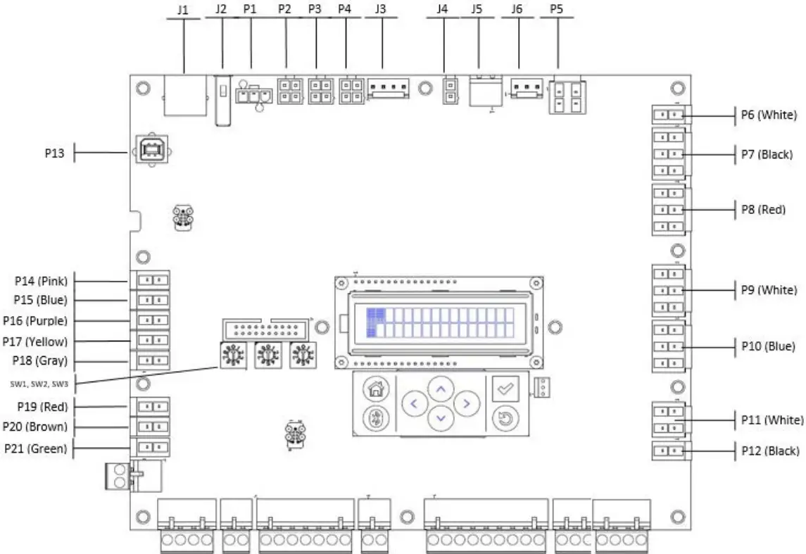
Table 4. Symbio 700 factory connections
| Factory Connection | Function | Pin # | Signal |
| P1 | Modbus Communication | 1 | GND |
| 2 | Modbus – | ||
| 3 | Modbus + | ||
| P2 | IMC Communication | 1 | 24VAC Out |
| 2 | GND | ||
| 3 | IMC + | ||
| 4 | IMC – | ||
| P3 | IMC Communication | 1 | 24VAC Out |
| 2 | GND | ||
| 3 | IMC + | ||
| 4 | IMC – | ||
| P4 | IMC Communication | 1 | 24VAC Out |
| 2 | GND | ||
| 3 | IMC + | ||
| 4 | IMC – |
Table 4. Symbio 700 factory connections (continued)
| Factory Connection | Function | Pin # | Signal |
|
P5 |
Indoor Fan | 1 | Common |
| 2 | Indoor Fan Run Command | ||
| 3 | Common | ||
| 4 | Indoor Fan High Speed | ||
| P6 | Power for Outdoor Fan and SOV Outputs | 1 | 24VAC In |
| 2 | GND | ||
| P7 | Outdoor Fan Outputs | 1 | Outdoor Fan 1 |
| 2 | GND | ||
| 3 | Outdoor Fan 2 | ||
| 4 | GND | ||
| 5 | Outdoor Fan 3 | ||
| 6 | GND | ||
| P8 | Compressor 1 Circuit | 1 | 24VAC Pass-through |
| 2 | 24VAC Pass-through | ||
| 3 | Compressor 1 Proving | ||
| 4 | Common | ||
| 5 | Compressor 1 Run | ||
| 6 | Compressor 1 Unloader | ||
| P9 |
Compressor 2 Circuit | 1 | 24VAC Pass-through |
| 2 | 24VAC Pass-through | ||
| 3 | Compressor 2 Proving | ||
| 4 | Common | ||
| 5 | Compressor 2 Run | ||
| 6 | Compressor 2 Unloader | ||
| P11 | Switchover Valves | 1 | Switchover Valve 1 |
| 2 | GND | ||
| 3 | Switchover Valve 2 | ||
| 4 | GND | ||
| P12 | ECM Fan Control | 1 | ECM Fan Control Output |
| 2 | GND | ||
| P13 | USB Service Tool | ||
| P14 | Spare Input | 1 | Spare |
| 2 | GND | ||
| P15 | Outdoor Air Temperature | 1 | Outdoor Air Temperature |
| 2 | GND | ||
| P16 | Coil Temperature 1 | 1 | Coil Temperature 1 Input |
| 2 | GND | ||
| P17 | Coil Temperature 2 | 1 | Coil Temperature 2 Input |
| 2 | GND | ||
| P19 | Circuit 1 LPC | 1 | 24Vac Out |
| 2 | Circuit 1 LPC Input |
Table 4. Symbio 700 factory connections (continued)
| Factory Connection | Function | Pin # | Signal |
| P20 | Circuit 2 LPC | 1 | 24Vac Out |
| 2 | Circuit 2 LPC Input | ||
| P21 | Spare | 1 | 24Vac Out |
| 2 | Spare | ||
| J1 | Ethernet | ||
| J2 | USB Host a | ||
| J3 | IMC Communication | 1 | 24V DC Power out |
| 2 | GND | ||
| 3 | IMC + | ||
| 4 | IMC – | ||
| J4 | Input Power | 1 | 24VAC In/Out |
| 2 | GND | ||
| J5 | Input Power | 1 | 24VAC In/Out |
| 2 | GND | ||
| J6 | Phase Monitor Input | 1 | 24VAC Out |
| 2 | Phase Monitor Input | ||
| 3 | GND | ||
| SW1 | BACnet Address | NA | |
| SW2 | BACnet Address | NA | |
| SW3 | BACnet Address | NA |
(a) USB HOST not intended to charge mobile phones
Figure 4. Symbio 700 field connections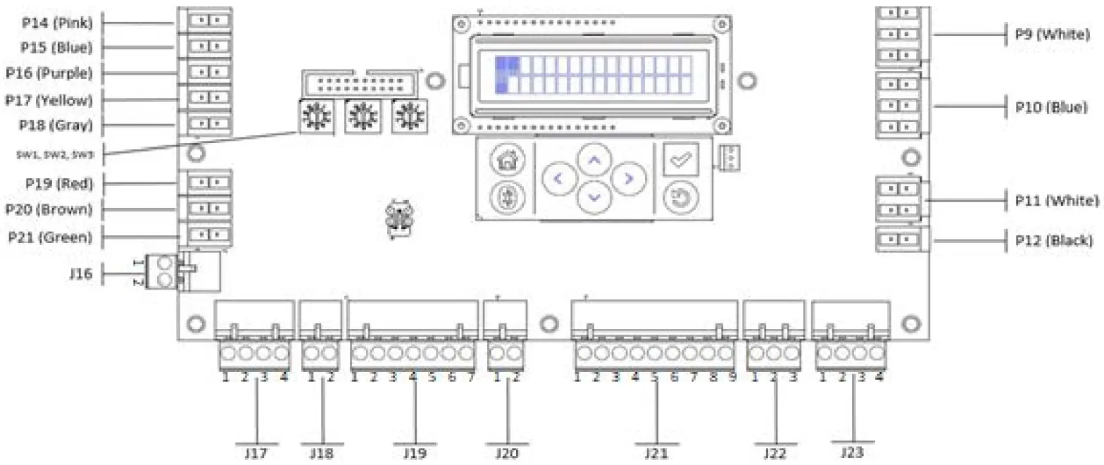
Table 5. Symbio 700 field connections
| Customer Connections | Function | Pin # | Signal |
| J16 | Demand Shed/Demand Limit Connection | 1 | 24VAC Out |
| 2 | Demand Shed/Demand Limit Input | ||
| J17 | BACnet Communication Connections | 1 | BACnet + |
| 2 | BACnet – | ||
| 3 | BACnet + | ||
| 4 | BACnet – | ||
| J18 | Equipment Shutdown Input Connections | 1 | 24VAC Out |
| 2 | Equipment Shutdown Input | ||
|
J19 |
Zone Sensor Connections | 1 | Space/Zone Temperature |
| 2 | GND | ||
| 3 | Cool Setpoint | ||
| 4 | Mode | ||
| 5 | Heat Setpoint | ||
| 6 | GND | ||
| 7 | 24VAC Out | ||
| J20 | Occupancy Connections | 1 | 24VAC Out |
| 2 | Occupancy Switch | ||
| J21 | Thermostat Connections | 1 | 24VAC Out |
| 2 | Y1 | ||
| 3 | W1/O | ||
| 4 | G | ||
| 5 | W2 | ||
| 6 | Y2 | ||
| 7 | X2 | ||
| 8 | 1.5K Ohms Pull-down | ||
| 9 | GND | ||
| J22 | Space CO2 | 1 | 24VDC Out |
| 2 | Input (0-10Vdc) | ||
| 3 | GND | ||
| J23 | Space Humidity | 1 | 24VDC Out |
| 2 | Input (4-20mA) | ||
| 3 | GND | ||
| 4 | NA |
Figure 5. Symbio 700 indoor option module factory connections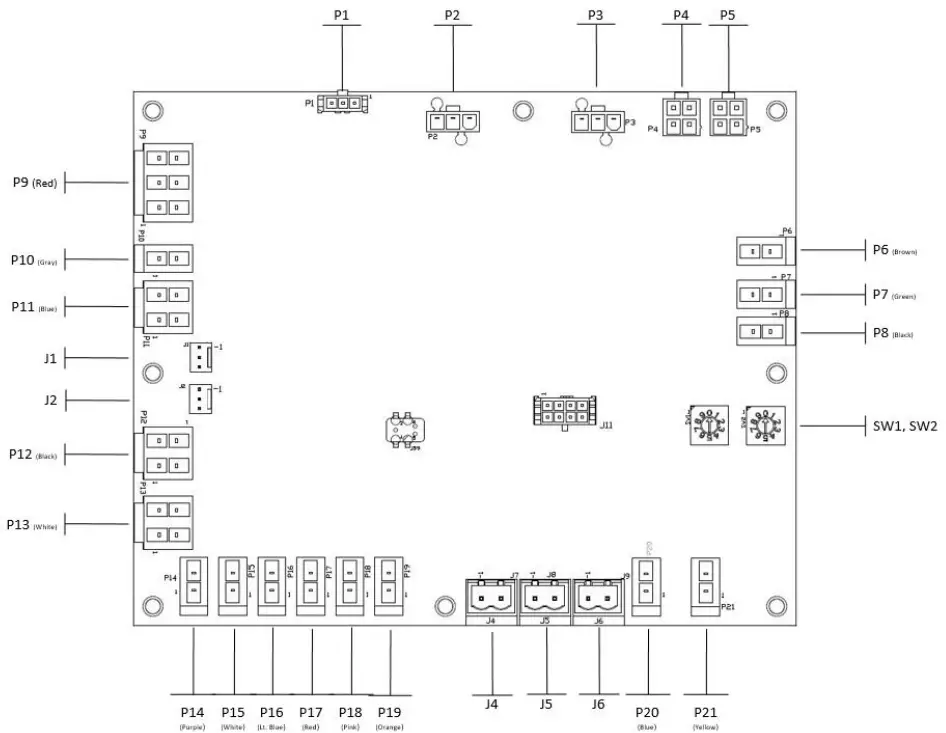
Table 6. Symbio 700 indoor option module factory connections
| Factory Connections | Function | Pin # | Signal |
| P4 | IMC Communication | 1 | 24VAC In/Out |
| 2 | GND | ||
| 3 | IMC + | ||
| 4 | IMC – | ||
| P5 | IMC Communication | 1 | 24VAC In/Out |
| 2 | GND | ||
| 3 | IMC + | ||
| 4 | IMC – | ||
| P6 | Electric Heat Stage 1 | 1 | Electric Heat Stage 1 Output |
| 2 | GND | ||
| P7 | Electric Heat Stage 2 | 1 | Electric Heat Stage 2 Output |
| 2 | GND | ||
| P14 | Discharge Air Temp | 1 | Discharge Air Temperature Input |
| 2 | GND | ||
| P16 | frost | 1 | 24Vac Out |
| 2 | FroStat Input | ||
| SW1 | Module Address | NA | NA |
| SW2 | Module Address | NA | NA |
Thermostats and Zone Sensors
Thermostats
Customers occasionally require operation with a conventional thermostat rather than a zone sensor. Non-Trane building controllers typically provide an interface to HVAC equipment based on a conventional thermostat interface. Units applied with this type of controller need to accept conventional thermostat inputs. Conventional thermostat signals represent direct requests for unit functions. This function provides inputs for the thermostat signals and processing to enhance reliability and performance. Compressor protection and reliability enhancement functions (HPC, LPC, minimum On/Off timers, etc.) all operate the same whether applied with zone sensors or a conventional thermostat. Logic is also provided to cause appropriate unit functions when inappropriate thermostat signals are provided. Simultaneous calls for heating and cooling will be ignored, and the fan will be turned on with a call for heating or cooling even if the fan request is not detected. If the thermostat is immediately changed from a heating to a cooling call or vice versa, there will be a delay before the new mode will initiate.
Table 7. Thermostat signals
Thermostat Operation
| J21 terminal | (1) R 24VAC power to the thermostat (2) Y1 Call for stage 1 of cooling (6) Y2 Call for stage 2 of cooling (4) G Call for supply fan (3) W1 Call for stage 1 of heating (5) W2 Call for stage 2 of heating |
| Heat pump only | (7) X2 Call for emergency heat (3) O Switchover valve On = cooling, Off = heating |
| Conventional thermostat – gas/ electric, electric heat | G (fan) Fan runs continuously Y1 (first stage of cooling) Compressor 1 runs Y2 + Y2 (second stage of cooling) Compressor 1 and Compressor 2 runs W1 (first stage of heating) Electric first stage operates W2 (second stage of heating) Electric second stage operates |
| Conventional thermostat – heat pump | G (fan) Fan runs continuously O (reversing valve during cooling) Reversing valve in cool mode Y1 + O (first stage cooling) Compressor 1 run Y1 + Y2 + O (second stage of cooling) Compressor 1 and Compressor 2 will run |
Zone Sensors
A 10k ohm resistance type 2 thermistor can be wired to terminals J19-1 and J19-2 as input for space temperature.
Averaging
In some applications, 1 zone sensor does not give a good representation of zone temperature. The internal thermistors, 10K ohm resistance @ 25C/77F, can be wired as shown below in order to provide an average input to the J19-1 and J19-2 terminals
Figure 6. Zone sensors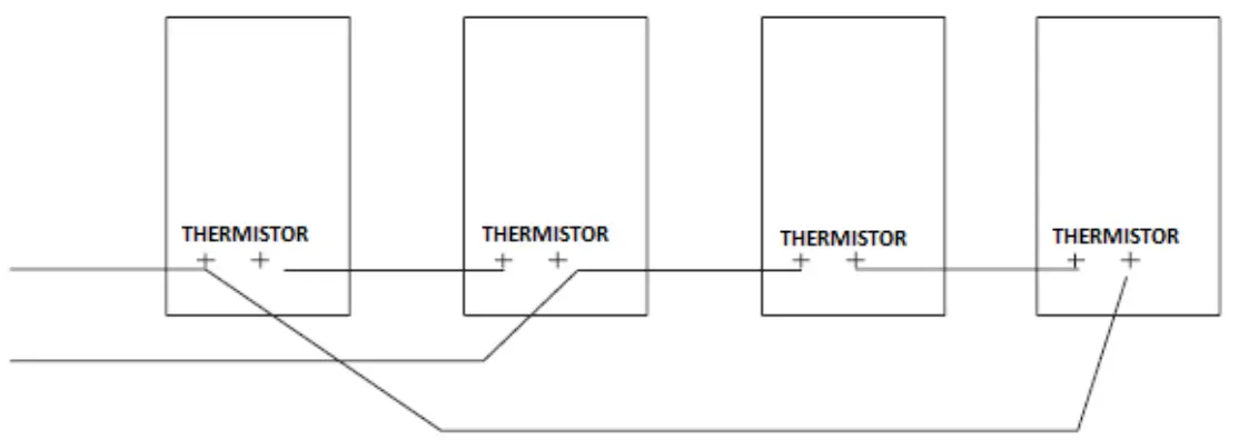
Communication Protocols
BACnet (ANSI/ASHRAE Standard 135-2016)
The Symbio 700 controller supports communication using BACnet MS/TP, BACnet IP, or BACnet/ Zigbee (Air-Fi™ Wireless). This allows the controller to communicate with most building automation systems. For more information on this protocol, see BACnet Integration to Odyssey Units with Symbio 700 Controls (ACC-SVP001).
LonTalk
The Symbio 700 Controller supports communication using LonTalk when the Tracer USB LonTalk Module is installed. This allows the controller to communicate with most building automation systems. For more information on this protocol, see LonTalk Integration to Odyssey Units with Symbio 700 Controls (ACC-SVP002).
Trane – by Trane Technologies (NYSE: TT), a global innovator – creates comfortable, energy-efficient indoor environments for commercial and residential applications. For more information, please visit.trane.com or tranetechnologies.com.
Trane has a policy of continuous product and product data improvements and reserves the right to change design and specifications without notice. We are committed to using environmentally conscious print practices.
BAS-SVU054A-EN 10 Jun 2020
Supersedes (New)
©2020 Trane


