IND308/B520 Replacement Quick Guide
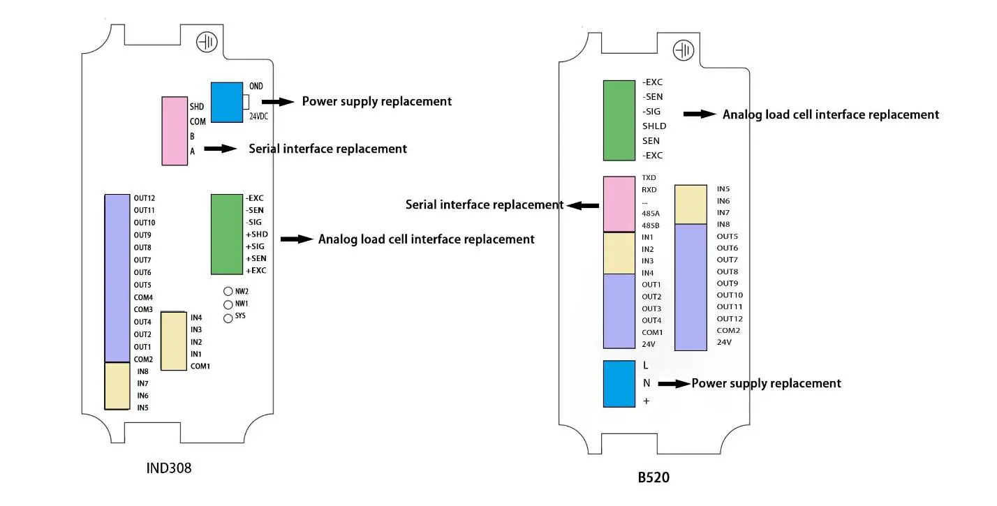
Hardware Replacement
- Power supply NoticeC30 requires 24VDC power supply
Pin Description GND Negative terminal +24VDC Positive terminal - Replacement of analog load cell interface follows the sequence of B520 wire
- Serial interface
IND308 PIN B520 PIN Description 485A 485A RS485 RxD+ 485B 485B RS485 RxD- COM COM Common SHD Shield
Scale calibration
Enter “Scale”, set “Capacity & Increment” Enter “Capacity & Increment”, set F1.2 → “Capacity” F1.3 → “Increment” | Enter “Calibration”,”Linearity” set to “Disabled” 1. Enter “Set Zero”, empty the scale and press” 2. Enter “Span Calibration”, enter “Test load 1”, and press “ |
PLC Mode DI/O Definition
| Input replacement | Output replacement | ||||
| IND308 PIN | 8520 PIN | Description | IND308 PIN | B520 PIN | Description |
| IN1 | IN1 | Start/Stop | OUT1 | OUT1 | Fast Feeding SP1 |
| 1N2 | 1N2 | Emergency Stop | OUT2 | OUT2 | Middle Feeding SP2 |
| 1N3 | 1N4 | Tolerance Accepted | OUT3 | OUT3 | Fine Feeding/ Spill Pr |
| 1N4 | 1N5 | Sever Valve ON OK | OUT4 | OUT4 | Discharge |
| COM1 | COM1 | I/O external power supply | OUT5 | OUT8 | Out of Tolerance |
| +24VDC | +24VDC | OUT6 | OUT10 | Near Zero | |
| 1N5 | 1N6 | Tare | OUT7 | OUT11 | Sever Valve Output |
| 1N6 | IN7/IN8 | Hopper Ready | |||
| COM2 | COM2 | I/O external power supply | |||
| +24VDC | +24VDC | ||||
PLC Mode Parameters setting
Enter “Application”, and set F2.1:0 → “Work Mode”: “PLC Mode” | Enter “Control Mode”, and set F2.3: 0 → “Output Type”: “Concurrent” F2.3: 1 → “Output Type”: “Independent” F2.6: 0 → “Judge Tolerance”: “Disabled” F2.6: 1 → “Judge Tolerance”: “Enabled” F3.18: 0 → “Discharge Near Zero”: “Disabled” F3.18: 1 → “Discharge Near Zero”: “Enabled” F2.5: 0 → “Power Up Mode Continue Bagging”: “Continue Bagging” F2.5: 1 → “Power Up Mode Continue Bagging”: “Empty Reset” |
Enter “Time”, and set F3.1.1 → “SP1 Inhibit Time” F3.1.2 → “SP2 Inhibit Time” F3.1.3 → “Spill Inhibit Time” F3.2 → “Stable Time” F3.3 → “Before Discharge Off” F3.4 → “After Discharge Off” F3.16 → “Jog Time” | Enter “Input”, if any input has no connection, set the input as “None”. If any input function changes, set the input as corresponding function.
|
Bulk Grain Mode DI/O Definition
| Input replacement | Output replacement | ||||
| IND308 PIN | 8520 PIN | Description | IND308 PIN | B520 PIN | Description |
| IN1 | IN1 | Start/Stop | OUT1 | OUT1 | Fast Feeding SP1 |
| IN2 | IN2 | Emergency Stop | OUT2 | OUT2 | Middle Feeding SP2 |
| IN3 | IN3 | Last Package | OUT3 | OUT3 | Fine Feeding/Spill Pr |
| IN4 | IN4 | Tolerance Accepted | OUT4 | OUT4 | Discharge |
| IN5 | IN5 | Sever Valve ON OK | OUTS | OUT8 | Out of Tolerance |
| COM1 | COM1 | I/O external power supply | OUT6 | OUT10 | Near Zero |
| +24VDC | +24VDC | OUT7 | OUT11 | Sever Valve Output | |
| IN6 | INC | Upper Hopper Low | |||
| IN7 | IN7/IN8 | Lower Hopper High | |||
| IN8 | IN7/IN8 | Hopper Ready | |||
| COM2 | COM2 | I/O external power supply | |||
| +24VDC | +24VDC | ||||
Bulk Grain Mode Parameters Setting
Enter “Application”, and set | Enter “Control Mode”, and set F2.3: 0 → “Output Type”: “Concurrent” F2.3: 1 → “Output Type”: “Independent” F3.10 → “Periodic Zero Cycles” F2.6: 0 → “Judge Tolerance”: “Disabled” F2.6: 1 → “Judge Tolerance”: “Enabled” F2.5: 0 → “Power Up Mode Continue Bagging”: “Continue Bagging” F2.5: 1 → “Power Up Mode Continue Bagging”: “Empty Reset” Enter “Signal Mode”, and set F2.7: 1 → “Upper Hopper Low”: “Default On” F2.7: 2 → “Upper Hopper Low”: “Default Off” F2.8: 1 → “Lower Hopper High”: “Default On” F2.8: 2 → “Lower Hopper High”: “Default Off” |
Enter “Time”, and set F3.1.1 → “SP1 Inhibit Time” F3.1.2 → “SP2 Inhibit Time” F3.1.3 → “Spill Inhibit Time” F3.2 → “Stable Time” F3.3 → “Before Discharge Off” F3.4 → “After Discharge Off” F3.16 → “Jog Time” | Enter “Input”, if any input has no connection, set the input as “None”. If any input function changes, set the input as corresponding function. |
No Hopper Mode DI/O Definition
| Input replacement | Output replacement | ||||
| IND308 PIN | 8520 PIN | Description | IND308 PIN | B520 PIN | Description |
| IN1 | INI | Start (Auto)/ Stop (Manual) | OUT1 | OUTI | Fast Feeding SPI |
| IN2 | IN2 | Emergency Stop | OUT2 | OUT2 | Middle Feeding SP2 |
| IN3 | IN3 | Clamp/Loose | OUTS | OUTS | Fine Feeding/Spill Pr |
| IN4 | IN4 | Tolerance Accepted | OUT4 | OUT4 | Discharge |
| COM1 +24VDC | COM1 +24VDC | I/O external power supply | OUT5 OUT6 | OUT5 OUT6 | Clamp Flap/Drop |
| IN5 | INS | Sever Valve ON OK | OUT7 | OUT7 | Cycle Complete |
| IN6 | IN6 | Upper Hopper Low | OUTS | OUT8 | Out of Tolerance |
| IN7 | IN7/IN8 | Lower Hopper High | OUT9 | OUT1O | Near Zero |
| IN8 | IN7/IN8 | Hopper Ready | OUT1O | OUTI I | Sever Valve Output |
| COM2 | COM2 | I/O external power supply | |||
| +24VDC | +24VDC | ||||
Have Hopper Mode Parameters Setting
Enter “Application”, and set F2.1: 2 → “Work Mode”: “Have Hopper Mode”Enter “Sequence”, and set F2.16: 0 → “Flap/Drop Mode”: “Flap” F2.16: 1 → “Flap/Drop Mode”: “Drop” F3.7 → “Final Flap/Drop Times” F3.5 → “Flap Interval” F3.11 → “Preset Packages” F3.13 → “Ton Bag Weight” | Enter “Control Mode”, and set F2.3: 0 → “Output Type”: “Concurrent” F2.3: 1 → “Output Type”: “Independent” F3.10 → “Periodic Zero Cycles” F2.6: 0 → “Judge Tolerance”: “Disabled” F2.6: 1 → “Judge Tolerance”: “Enabled” F3.18: 0 → “Discharge Near Zero”: “Disabled” F3.18: 1 → “Discharge Near Zero”: “Enabled” F2.5: 0 → “Power Up Mode Continue Bagging”: “Continue Bagging” F2.5: 1 → “Power Up Mode Continue Bagging”: “Empty Reset” Enter “Signal Mode”, and set F2.7: 1 → “Upper Hopper Low”: “Default On” F2.7: 2 → “Upper Hopper Low”: “Default Off” F2.8: 1 → “Lower Hopper High”: “Default On” F2.8: 2 → “Lower Hopper High”: “Default Off” |
Enter “Time”, and set F3.1.1 → “SP1 Inhibit Time” F3.1.2 → “SP2 Inhibit Time” F3.1.3 → “Spill Inhibit Time” F3.2 → “Stable Time” F3.3 → “Before Discharge Off” F3.4 → “After Discharge Off” F3.16 → “Jog Time” F3.14 → “Clamp Delay” F3.15 → “Delay to Declamp” | Enter “Input”, if any input has no connection, set the input as “None”. If any input function changes, set the input as corresponding function. Enter “Output”, if any output has no connection, set the output as “None”. If any output function changes, set the output as corresponding function. |
No Hopper Mode DI/O Definition
| Input replacement | Output replacement | ||||
| IND308 PIN | 8520 PIN | Description | IND308 PIN | B520 PIN | Description |
| IN1 | IN1 | Start (Auto) / Stop (Manual) | OUT1 | OUT1 | fEE.,At]. SP1 |
| 1N2 | IN2 | Emergency Stop | OUT2 | OUT2 | rt-CETU=} SP2 |
| 1N3 | IN3 | Clamp/Loose | OUT3 | OUT3 | Fast Feeding SP1 |
| IN4 | IN4 | Tolerance Accepted | OUT4 | OUTS | Middle Feeding SP2 |
| COM1 | COM 1 | I/O external power supply | OUTS | OUT6 | Fine Feeding/Spill Pr |
| +24VDC | +24VDC | OUT6 | OUT7 | Clamp | |
| INS | INS | Sever Valve ON OK | OUT7 | OUT8 | Flap/Drop |
| 1N6 | Upper Hopper Low | OUT8 | OUT9 | Cycle Complete | |
| IN? | IN7/IN8 | Lower Hopper High | OUT9 | OUT1O | Out of Tolerance |
| IN8 | IN7/IN8 | Bag Clamped OK | OUT1O | OUT11 | Rise Platform |
| COM2 | COM2 | I/O external power supply | |||
| +24VDC | +24VDC | ||||
No Hopper Mode Parameters Setting
Enter “Application”, and set | Enter “Control Mode”, and set F2.3: 0 → “Output Type”: “Concurrent” F2.3: 1 → “Output Type”: “Independent” F3.10 → “Periodic Zero Cycles” F2.6: 0 → “Judge Tolerance”: “Disabled” F2.6: 1 → “Judge Tolerance”: “Enabled” F3.18: 0 → “Discharge Near Zero”: “Disabled” F3.18: 1 → “Discharge Near Zero”: “Enabled” F2.5: 0 → “Power Up Mode Continue Bagging”: “Continue Bagging” F2.5: 1 → “Power Up Mode Continue Bagging”: “Empty Reset” Enter “Signal Mode”, and set F2.7: 1 → “Upper Hopper Low”: “Default On” F2.7: 2 → “Upper Hopper Low”: “Default Off” F2.8: 1 → “Lower Hopper High”: “Default On” F2.8: 2 → “Lower Hopper High”: “Default Off” |
Enter “Time”, and set F3.1.1 → “SP1 Inhibit Time” F3.1.2 → “SP2 Inhibit Time” F3.1.3 → “Spill Inhibit Time” F3.2 → “Stable Time” F3.16 → “Jog Time” F3.14 → “Clamp Delay” F3.15 → “Delay to Declamp” | Enter “Input”, if any input has no connection, set the input as “None”. If any input function changes, set the input as corresponding function. Enter “Output”, if any output has no connection, set the output as “None”. If any output function changes, set the output as corresponding function. |
Dual Scale Mode DI/O Definition
| Input replacement | Output replacement | ||||
| IND308 PIN | 8520 PIN | Description | IND308 PIN | 8520 PIN | Description |
| IN I | NiI | Start/Stop | OUT I | OUTI | Fast Feeding SP1 |
| IN2 | IN2 | Emergency Stop | 0 UT2 | 0 UT2 | Middle Feeding SP2 |
| IN3 | INS | Clamp/Loose | 0 UT3 | 0 UT3 | Fine Feeding/Spill Pr |
| IN4 | IN4 | Tolerance Accepted | 0 UT4 | 0 UT4 | Discharge |
| COMI | COMI | I/O external power supply | OUTS | OUTS | Clamp |
| +24VDC | +24VDC | OUT7 | OUT7 | Cycle Complete | |
| INS | INS | Dual Scale Sync | 0 UT8 | 0 UT8 | Out of Tolerance |
| IN6 | IN6 | Upper Hopper Low | 0 UT9 | OUTIO | Near Zero |
| IN7 | INI/IN8 | Lower Hopper High | OUT 10 | OUTI2 | Dual Scale Sync |
| INS | IN7/IN8 | Hopper Ready | |||
| COM2 | COM2 | I/O external power supply | |||
| +24VDC | +24VDC | ||||
Dual Scale Mode Parameters Setting
Enter “Application”, and set F2.1: 5 → “Work Mode”: “Dual Scale Mode” Enter “Sequence”, and set F3.11 → “Preset Packages” F2.11: 0 → “Master/Slave Mode”: Master Scale F2.11: 1 → “Master/Slave Mode”: Slave Scale F2.12: 0 → “Dual Scale Discharge”: “Combination” F2.12: 1 → “Dual Scale Discharge”: “Interlock” | Enter “Control Mode”, and set F2.3: 0 → “Output Type”: “Concurrent” F2.3: 1 → “Output Type”: “Independent” F3.10 → “Periodic Zero Cycles” F2.6: 0 → “Judge Tolerance”: “Disabled” F2.6: 1 → “Judge Tolerance”: “Enabled” F3.18: 0 → “Discharge Near Zero”: “Disabled” F3.18: 1 → “Discharge Near Zero”: “Enabled” F2.5: 0 → “Power Up Mode Continue Bagging”: “Continue Bagging” F2.5: 1 → “Power Up Mode Continue Bagging”: “Empty Reset” Enter “Signal Mode”, and set F2.7: 1 → “Upper Hopper Low”: “Default On” F2.7: 2 → “Upper Hopper Low”: “Default Off” F2.8: 1 → “Lower Hopper High”: “Default On” F2.8: 2 → “Lower Hopper High”: “Default Off” |
Enter “Time”, and set F3.1.1 → “SP1 Inhibit Time” F3.1.2 → “SP2 Inhibit Time” F3.1.3 → “Spill Inhibit Time” F3.2 → “Stable Time” F3.3 → “Before Discharge Off” F3.4 → “After Discharge Off” F3.16 → “Jog Time” F3.14 → “Clamp Delay” F3.15 → “Delay to Declamp” |
|


