![]()
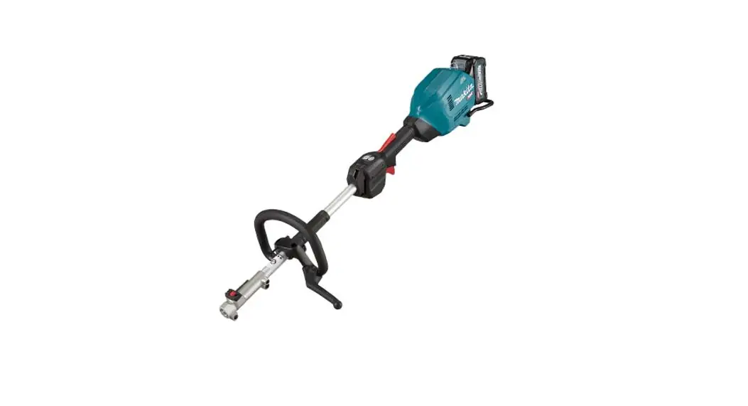
Cordless Multi-Function
Power Head
INSTRUCTION MANUAL
 |  |  |  |  |
(Original instructions)
SPECIFICATIONS
| Model: | UX01G | |
| No load speed (without attachment) | Low | 0 – 5,700 min”‘ |
| Medium | 0 – 8,200 mind | |
| High | 0 – 9,700 min”‘ | |
| Overall length (without battery cartridge) | 1,001 mm | |
| Rated voltage | D.C. 36 V – 40 V max | |
| Net weight | 5.3 kg – 12.5 kg | |
| Protection degree | IPX4 | |
- Due to our continuing program of research and development, the specifications herein are subject to change without notice.
- Specifications may differ from country to country.
- The weight may differ depending on the attachment(s), including the battery cartridge.
- The lightest and heaviest combinations, according to EPTA-Procedure 01/2014, are shown in the table.
Applicable battery cartridge and charger
| Type | Battery cartridge | ||||
| BL4020 | BL4025 | BL4040 | BL4050F | BL4080F | |
| Brushcutter attachment | Available | Available | Recom- mended | Recom- mended | Recom- mended |
| String trimmer attachment | Available | Available | Recom- mended | Recom- mended | Recom- mended |
| Rotary scissors attachment | Available | Available | Recom- mended | Recom- mended | Recom- mended |
| Grass trimmer attachment | Available | Available | Recom- mended | Recom- mended | Recom- mended |
| Hedge trimmer attachment | Available | Recom- mended | Recom- mended | Recom- mended | Recom- mended |
| Ground trimmer attachment | Available | Recom- mended | Recom- mended | Recom- mended | Recom- mended |
| Pole saw attachment | Available | Available | Recom- mended | Recom- mended | Recom- mended |
| Cultivator attachment | Available | Available | Recom- mended | Recom- mended | Recom- mended |
| Edger attachment | Available | Recom- mended | Recom- mended | Recom- mended | Recom- mended |
| Coffee harvester attachment | Available | Available | Recom- mended | Recom- mended | Recom- mended |
| Power brush attachment | Available | Available | Recom- mended | Recom- mended | Recom- mended |
| Power sweep attachment | Available | Available | Recom- mended | Recom- mended | Recom- mended |
| Blower attachment | Available | Available | Recom- mended | Recom- mended | Recom- mended |
| Charger | DC4ORA/ DC4ORB / DC4ORC |
- Some of the battery cartridges and chargers listed above may not be available depending on your region of residence.
![]() WARNING: Only use the battery cartridges and chargers listed above. Use of any other battery cartridges and chargers may cause injury and/or fire.
WARNING: Only use the battery cartridges and chargers listed above. Use of any other battery cartridges and chargers may cause injury and/or fire.
Recommended cord connected power source
| Portable power pack | PDC01 / PDC1200 |
- The cord-connected power source(s) listed above may not be available depending on your region of residence.
- Before using the cord-connected power source, read instructions and cautionary markings on them.
No-load speed with attachment
| Model | Rotation speed | |||
| Low | Medium | High | ||
| EM401MP | 0 – 4,200 min”‘ | 0 – 6,000 min”‘ | 0 – 7,100 min”‘ | |
| EM404MP / EM406MP | 0 – 3,500 min”‘ | 0 – 5,000 min”‘ | 0 – 6,000 min”‘ | |
| EM407MP | Upper blade | 0 – 220 min”‘ | 0 – 310 mind | 0 – 370 mind |
| Lower blade | 0 – 470 mind | 0 – 670 mind | 0 – 790 mind | |
| EM408MP / EM409MP | 0 – 4,200 min”‘ | 0 – 6,000 min”‘ | 0 – 7,100 min”‘ | |
| EN401MP / EN410MP / EN420MP (Strokes per minute) | 0 – 2,400 m i n”‘ | – “‘ 0 3,400 mi n | 0 – 4,000 min’ | |
| EY401MP (chain speed) | 0 – 12 m/s | 0 – 17 m/s | 0 – 20 m/s | |
| EY403MP (chain speed) | 0 – 11 m/s | 0 – 16 m/s | 0 – 19 m/s | |
| KR400MP | 0 – 160 min”‘ | 0 – 230 mind | 0 – 280 mind | |
| KR401MP | 0 – 130 min”‘ | 0 – 190 mind | 0 – 230 mind | |
| EE400MP | 0 – 2,800 min”‘ | 0 – 4,000 min”‘ | 0 – 4,700 min”‘ | |
| EJ400MP | 0 – 1,600 min”‘ | 0 – 2,300 min”‘ | 0 – 2,800 min”‘ | |
| BR400MP | 0 – 130 min”‘ | 0 – 190 mind | 0 – 230 mind | |
| SW400MP | 0 – 130 min”‘ | 0 – 190 mind | 0 – 230 mind | |
| UB400MP | 0 – 5,650 min”‘ | 0 – 7,800 mind | 0 – 9,450 mind | |
| UB401MP | 0 – 5,650 min”‘ | 0 – 7,800 mind | 0 – 9,450 mind | |
Approved attachment
| Type | Model |
| Brushcutter attachment | EM401 MP / EM404MP |
| String trimmer attachment | EM406MP |
| Rotary scissors attachment | EM407MP |
| Grass trimmer attachment | EM408MP / EM409MP |
| Hedge trimmer attachment | EN401 MP / EN410MP |
| Ground trimmer attachment | EN420MP |
| Pole saw attachment | EY401 MP / EY403MP |
| Cultivator attachment | KR400MP / KR401 MP |
| Edger attachment | EE400MP |
| Coffee harvester attachment | EJ400MP |
| Shaft extension attachment | LE400MP |
| Power brush attachment | BR400MP |
| Power sweep attachment | SW400MP |
| Blower attachment | UB400MP / UB401 MP |
Symbols
The followings show the symbols which may be used for the equipment. Be sure that you understand their meaning before use.![]()
![]() Read the instruction manual.
Read the instruction manual.![]() Take particular care and attention.
Take particular care and attention.![]() Do not expose to moisture.
Do not expose to moisture.
![]() Ni-MHLi-ion Only for EU countries Due to the presence of hazardous components in the equipment, waste electrical and electronic equipment, accumulators and batteries may have a negative impact on the environment and human health. Do not dispose of electrical and electronic appliances or batteries with household waste! In accordance with the European Directive on waste electrical and electronic equipment and on accumulators and batteries and waste accumulators and batteries, as well as their adaptation to national law, waste electrical equipment, batteries and accumulators should be stored separately and delivered to a separate collection point for municipal waste, operating in accordance with the regulations on environmental protection. This is indicated by the symbol of the crossed-out wheeled bin placed on the equipment.
Ni-MHLi-ion Only for EU countries Due to the presence of hazardous components in the equipment, waste electrical and electronic equipment, accumulators and batteries may have a negative impact on the environment and human health. Do not dispose of electrical and electronic appliances or batteries with household waste! In accordance with the European Directive on waste electrical and electronic equipment and on accumulators and batteries and waste accumulators and batteries, as well as their adaptation to national law, waste electrical equipment, batteries and accumulators should be stored separately and delivered to a separate collection point for municipal waste, operating in accordance with the regulations on environmental protection. This is indicated by the symbol of the crossed-out wheeled bin placed on the equipment.
Intended use
This cordless multi-function power head is intended for driving an approved attachment listed in the section “SPECIFICATIONS” of this instruction manual. Never use the unit for other purpose.![]() WARNING: Read the instruction manual of the attachment as well as this instruction manual before using. Failure to follow the warnings and instructions may result serious injury.
WARNING: Read the instruction manual of the attachment as well as this instruction manual before using. Failure to follow the warnings and instructions may result serious injury.
Noise
| Attachment | Sound pressure level average | Sound power level average | Applicable standard | |||
| Li (dB (A)) | Uncertainty K (dB (A)) | L.,” (dB (A)) | Uncertainty K (dB (A)) | |||
| EM401 MP (as a brushcutter) | 80. | 1. | 95. | 3. | 15022868 | |
| (IS011806-1) | ||||||
| EM401 MP (as a string trimmer) | Nylon cutting head | 80. | 1.0 | 94. | 2.0 | 19022868 |
| (!S011806-1)/ | ||||||
| EN50636-2-91 | ||||||
| Plastic blade | 79. | 1.0 | 91. | 2. | 19022868 | |
| OS011806-1)/ | ||||||
| EN50636-2-91 | ||||||
| EM404MP (as a brushcutter) | 79. | 1. | 92.0 | 1.0 | 19022868 | |
| (15011806-1) | ||||||
| EM404MP (as a string trimmer) | Nylon cutting head | 81. | 1. | 92. | 1. | 19022868 |
| OS011806-1)1 | ||||||
| EN50636-2-91 | ||||||
| Plastic blade | 79. | 0.7 | 88. | 0.4 | 1S022868 | |
| (15011806-1)1 | ||||||
| EN50636-2-91 | ||||||
| EM406MP | Nylon cutting head | 81. | 0.6 | 93. | 2. | 19022868 |
| (1S011806-1)1 | ||||||
| EN50636-2-91 | ||||||
| Plastic blade | 79. | 0.4 | 88. | 0.6 | 15022868 | |
| (1S011806-1)1 | ||||||
| EN50636-2-91 | ||||||
| EM407MP | 85. | 2. | 99.0 | 1. | 19022868 | |
| (15011806-1) | ||||||
| EM408MP | Metal blade | 81. | 2. | 95. | 3.0 | 19022868 |
| (15011806-1) | ||||||
| Nylon cutting head | 80. | 1. | 93. | 3. | 15022868 | |
| OS011806-1)/ | ||||||
| EN50636-2-91 | ||||||
| Plastic blade | 81. | 1. | 92. | 3. | 19022868 | |
| (IS011806-1)1 | ||||||
| EN50636-2-91 | ||||||
| EM409MP | Nylon cutting head | 81. | 1. | 93. | 2. | 15022868 |
| (1S011806-1)1 | ||||||
| EN50636-2-91 | ||||||
| Plastic blade | 81.0 | 1. | 92. | 2. | 19022868 | |
| (1S011806-1)1 | ||||||
| EN50636-2-91 | ||||||
| EN401MP | 84 | 3 | 95 | 3 | EN62841-4-2 | |
| EN401MP + LE400MP | 85 | 3 | 96 | 3 | EN62841-4-2 | |
| Attachment | Sound pressure level average | Sound power level average | Applicable standard | ||
| L, (dB (A)) | Uncertainty K (dB (A)) | L.,” (dB (A)) | Uncertainty K (dB (A)) | ||
| EN410MP | 80 | 3 | 91 | 3 | EN62841-4-2 |
| EN410MP + LE400MP | 80 | 3 | 91 | 3 | EN62841-4-2 |
| EN420MP | 83 | 3 | 94 | 3 | EN62841-4-2 |
| EY401MP | 94 | 3 | 103 | 3 | 15022868 (15011680-1) |
| EY401MP + LE4OOMP | 85 | 3 | 103 | 3 | 15022868 (15011680-1) |
| EY403MP | 95 | 3 | 102 | 3 | 15022868 (I5011680-1) |
| EY403MP+LE400MP | 95 | 3 | 102 | 3 | 15022868 (15011680-1) |
| KR400MP | 78. | 0.7 | 87. | 1. | EN709 |
| KR401MP | 78. | 0.3 | 87. | 2.0 | EN709 |
| EE400MP | 76. | 2. | 88. | 2. | 15011789 / 2000/14/EC |
| EJ400MP | 83. | 0.6 | 94. | 2. | 15022868 (IS011806-1) |
| EJ400MP + LE400MP | 80. | 1. | 94.0 | 0.7 | 15022868 (15011806-1) |
| BR400MP | 80. | 1.0 | 89. | 0.8 | EN60335-2-72 |
| SW400MP | 80. | 0.2 | 88. | 0.6 | EN60335-2-72 |
| UB400MP | 92. | 2. | 104. | 1. | EN50636-2-100 |
| UB401MP | 86. | 2. | 97. | 1.0 | EN50636-2-100 |
- Even if the sound pressure level listed above is 80 dB (A) or less, the level under working may exceed 80 dB (A). Wear ear protection.
NOTE: The declared noise emission value(s) has been measured in accordance with a standard test method and may be used for comparing one tool with another.
NOTE: The declared noise emission value(s) may also be used in a preliminary assessment of exposure.![]() WARNING: Wear ear protection.
WARNING: Wear ear protection.![]() WARNING: The noise emission during actual use of the power tool can differ from the declared val- ue(s) depending on the ways in which the tool is used especially what kind of workpiece is processed.
WARNING: The noise emission during actual use of the power tool can differ from the declared val- ue(s) depending on the ways in which the tool is used especially what kind of workpiece is processed.![]() WARNING: Be sure to identify safety measures to protect the operator that are based on an estimation of exposure in the actual conditions of use (taking account of all parts of the operating cycle such as the times when the tool is switched off and when it is running idle in addition to the trigger time).
WARNING: Be sure to identify safety measures to protect the operator that are based on an estimation of exposure in the actual conditions of use (taking account of all parts of the operating cycle such as the times when the tool is switched off and when it is running idle in addition to the trigger time).
Vibration
| Attachment | Left handle (Front grip) | Right handle (Rear grip) | Applicable standard | |||
| ah (m/s2) | Uncertainty K (m/e) | ah (m/s2) | Uncertainty K (m/s’) | |||
| EM401 MP (as a brushcutter) | 2.5 or less | 2. | 2.5 or less | 2. | IS022867 | |
| (IS011806-1) | ||||||
| EM401MP (as a string trimmer) | Nylon cutting head | 4. | 2. | 3.0 | 2. | IS022867 |
| (IS011806-1) | ||||||
| Plastic blade | 2.5 or less | 2. | 2.5 or less | 2. | IS022867 | |
| (IS011806-1) | ||||||
| EM404MP (as a brushcutter) | 2.5 or less | 2. | 2.5 or less | 2. | IS022867 | |
| (IS011806-1) | ||||||
| EM404MP (as a string trimmer) | Nylon cutting head | 2.5 or less | 2. | 2.5 or less | 2. | IS022867 |
| (IS011806-1) | ||||||
| Plastic blade | 2.5 or less | 2. | 2.5 or less | 2. | IS022867 | |
| (IS011806-1) | ||||||
| Attachment | Left handle (Front grip) | Right handle (Rear grip) | Applicable standard | |||
| ah (m/s2) | Uncertainty K (m/s2) | ah (m/s2) | Uncertainty K (m/s2) | |||
| EM406MP | Nylon cutting head | 2.5 or less | 2. | 2 5 or less | 2. | 15022867 (15011806-1) |
| Plastic blade | 2.5 or less | 2. | 2 5 or less | 2. | 15022867 (I5011806-1) | |
| EM407MP | 2 5 or less | 2. | 2.5 or less | 2. | 15022867 (15011806-1) | |
| EM408MP | Metal blade | 2.5 or less | 2. | 2 5 or less | 2. | 15022867 (15011806-1) |
| Nylon cutting head | 2.5 or less | 2. | 2.5 or less | 2. | 15022867 (15011806-1) | |
| Plastic blade | 2.5 or less | 2. | 2 5 or less | 2. | 15022867 (15011806-1) | |
| EM409MP | Nylon cutting head | 2.5 or less | 2. | 2.5 or less | 2. | 15022867 (15011806-1) |
| Plastic blade | 2 5 or less | 2. | 2 5 or less | 2. | 15022867 (15011806-1) | |
| EN401MP | 3. | 2. | 2.5 or less | 2. | EN62841-4-2 | |
| EN401 MP + LE400MP | 5. | 2. | 3. | 2. | EN62841-4-2 | |
| EN410MP | 3. | 2. | 2 5 or less | 2. | EN62841-4-2 | |
| EN410MP + LE400MP | 4. | 2. | 2.5 or less | 2. | EN62841-4-2 | |
| EN420MP | 3. | 2. | 2 5 or less | 2. | EN62841-4-2 | |
| EY401MP | 2 5 or less | 2. | 2 5 or less | 2. | 15022867 (15011680-1) | |
| EY401MP + LE400MP | 2.5 or less | 2. | 2.5 or less | 2. | 15022867 (15011680-1) | |
| EY403MP | 4.0 | 2. | 2.5 or less | 2. | 15022867 (15011680-1) | |
| EY403MP+LE400MP | 3. | 2. | 2.5 or less | 2. | 15022867 (15011680-1) | |
| KR400MP | 2.5 or less | 2. | 2.5 or less | 2. | EN709 | |
| KR401MP | 2.5 or less | 2. | 2.5 or less | 2. | EN709 | |
| EE400MP | 2 5 or less | 2. | 2 5 or less | 2. | 15011789 | |
| EJ400MP | 4. | 2. | 4. | 2. | 15022867 (15011806-1) | |
| EJ400MP + LE4OOMP | 5. | 2. | 3. | 2. | 15022867 (15011806-1) | |
| BR400MP | 2.5 or less | 2. | 2 5 or less | 2. | EN60335-2-72 | |
| SW400MP | 3. | 2. | 2.5 or less | 2. | EN60335-2-72 | |
| UB4130MP | 5. | 2. | 2 5 or less | 3. | EN50636-2-100 | |
| U8401 MP | 2 5 or less | 2. | 2 5 or less | 2. | EN50636-2-100 | |
NOTE: The declared vibration total value(s) has been measured in accordance with a standard test method and may be used for comparing one tool with another.
NOTE: The declared vibration total value(s) may also be used in a preliminary assessment of exposure.![]() WARNING: The vibration emission during actual use of the power tool can differ from the declared value(s) depending on the ways in which the tool is used especially what kind of workpiece is processed.
WARNING: The vibration emission during actual use of the power tool can differ from the declared value(s) depending on the ways in which the tool is used especially what kind of workpiece is processed.![]() WARNING: Be sure to identify safety measures to protect the operator that are based on an estimation of exposure in the actual conditions of use (taking account of all parts of the operating cycle such as the times when the tool is switched off and when it is running idle in addition to the trigger time).
WARNING: Be sure to identify safety measures to protect the operator that are based on an estimation of exposure in the actual conditions of use (taking account of all parts of the operating cycle such as the times when the tool is switched off and when it is running idle in addition to the trigger time).
EC Declaration of Conformity
For European countries only
The EC declaration of conformity is included as Annex A to this instruction manual.
SAFETY WARNINGS
General power tool safety warnings
![]() WARNING: Read all safety warnings, instructions, illustrations and specifications provided with this power tool. Failure to follow all instructions listed below may result in electric shock, fire and/or serious injury.
WARNING: Read all safety warnings, instructions, illustrations and specifications provided with this power tool. Failure to follow all instructions listed below may result in electric shock, fire and/or serious injury.
Save all warnings and instructions for future reference.
The term “power tool” in the warnings refers to your mains-operated (corded) power tool or battery-operated (cordless) power tool.
Additional safety instructions
Personal protective equipment
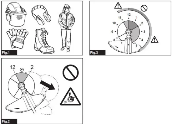
► Fig.1
- Wear safety helmet, protective goggles and protective gloves to protect yourself from flying debris or falling objects.
- Wear ear protection such as ear muffs to prevent hearing loss.
- Wear proper clothing and shoes for safe operation, such as a work overall and sturdy, non-slip shoes. Do not wear loose clothing or jewelry. Loose clothes, jewelry or long hair can be caught in moving parts.
- When touching the cutting blade, wear protective gloves. Cutting blades can cut bare hands severely.
Work area safety
- Before the operation, examine the work area for stones or other solid objects. They can be thrown or cause dangerous kickback and result in serious injury and/or property damage.
Electrical and battery safety
- Avoid dangerous environments. Don’t use the tool in dump or wet locations or expose it to rain. Water entering the tool will increase the risk of electric shock.
- Do not dispose of the battery(ies) in a fire. The cell may explode. Check with local codes for possible special disposal instructions.
- Do not open or mutilate the battery(ies). Released electrolyte is corrosive and may cause damage to the eyes or skin. It may be toxic if swallowed.
- Do not charge battery in rain, or in wet locations.
- Do not replace the battery with wet hands.
- Do not replace the battery in the rain.
- Do not wet the terminal of the battery with a liquid such as water, or submerge the battery. Do not leave the battery in the rain, nor charge, use, or store the battery in a damp or wet place. If the terminal gets wet or liquid enters inside of the battery, the battery may be short-circuited and there is a risk of overheating, fire, or explosion.
- After removing the battery from the tool or charger, be sure to attach the battery cover to the battery and store it in a dry place.
- If the battery cartridge gets wet, drain the water inside and then wipe it with a dry cloth. Dry the battery cartridge completely in a dry place before use.
Putting into operation
- The cutting tool has to be equipped with a guard. Never run the tool with damaged guards or without guards in place!
- Make sure there are no electrical cables, water pipes, gas pipes etc. that could cause a hazard if damaged by use of the tool.
Operation
- Always keep your hands, face, and clothes away from the cutting tool when it is rotating. Failure to do so may cause personal injury.
- During operation, keep bystanders or animals at least 15 m away from the tool. Stop the tool as soon as someone approaches.
- During operation, never stand on an unstable or slippery surface or a steep slope. During the cold season, beware of ice and snow and always ensure secure footing.
- Never work on a ladder or tree to avoid loss of control.
- When you leave the tool, even if it is a short time, always remove the battery cartridge. The unattended tool with the battery cartridge installed may be used by an unauthorized person and cause a serious accident.
- Before starting the tool, be sure that the cutting tool is not touching the ground and other obstacles such as a tree.
- . Check the cutting attachment frequently during operation for cracks or damages. Before the inspection, remove the battery cartridge and wait until the cutting attachment stops completely. Replace damaged cutting attachment immediately, even if it has only superficial cracks.
- Do not operate the tool in bad weather or if there is a risk of lightning.
- During operation always hold the tool with both hands. Never hold the tool with one hand during use.
- During operation, use the shoulder harness. Keep the tool on your right side firmly.
- Do not touch the gear case during and immediately after the operation. The gear case becomes hot during operation and can cause burn injury.
- Take a rest to prevent loss of control caused by fatigue. We recommend taking a 10 to 20-minute rest every hour.
- When you use the tool on the muddy ground, wet slope, or slippery places, pay attention to your footing.
- Avoid working in poor environment where increased user fatigue is expected.
- Do not use the tool in bad weather where visibility is limited. Failure to do so may cause fall or incorrect operation due to low visibility.
- Do not submerge the tool into a puddle.
- Do not leave the tool unattended outdoors in the rain.
- When wet leaves or dirt adhere to the suction mouth (ventilation window) due to rain, remove them.
- Do not use the tool in the snow.
Kickback (Blade thrust)
- Kickback (blade thrust) is a sudden reaction to a caught or bound cutting blade. Once it occurs, the tool is thrown sideway or toward the operator at great force and it may cause serious injury.
- Kickback occurs particularly when applying the blade segment between 12 and 2 o’clock to solids, bushes and trees with 3 cm or larger diameter.
► Fig.2
3. To avoid kickback:
- Apply the segment between 8 and 11 o’clock.
- Never apply the segment between 12 and 2 o’clock.
- Never apply the segment between 11 and 12 o’clock and between 2 and 5 o’clock, unless the operator is well trained and experienced and does it at his/her own risk.
- Never use cutting blades close to solids, such as fences, walls, tree trunks and stones.
- Never use cutting blades vertically, for such operations as edging and trimming hedges.
► Fig.3
Vibration
- People with poor circulation who are exposed to excessive vibration may experience injury to blood vessels or the nervous system. Vibration may cause the following symptoms to occur in the fingers, hands or wrists: “Falling asleep” (numbness), tingling, pain, stabbing sensation, alteration of skin color or of the skin. If any of these symptoms occur, see a physician!
- To reduce the risk of “white finger disease”, keep your hands warm during operation and well maintain the tool and accessories.
Transport
- Before transporting the tool, turn it off and remove the battery cartridge. Attach the cover to the cutting blade.
Maintenance
- Before doing any maintenance or repair work or cleaning the tool, always turn it off and remove the battery cartridge.
- When handling a cutter blade, always wear gloves and put the blade cover on the blade.
- Keep handles dry, clean and free from oil and grease. Keep all cooling air inlets clear of debris.
- Do not wash the tool with high-pressure water.
- When washing the tool, do not let water enter the electrical mechanism such as the battery, motor, and terminals.
- Perform inspection or maintenance in a place where rain can be avoided.
- After using the tool, remove the adhered dirt and dry the tool completely before storing it. Depending on the season or the area, there is a risk of malfunction due to freezing.
Storage
- Before storing the tool, perform full cleaning and maintenance. Remove the battery cartridge. Attach the cover to the cutting blade.
- Store the tool in a dry and high or locked location out of reach of children.
- When storing the tool, avoid direct sunlight and rain, and store it in a place where it does not get hot or humid.
Important safety instructions for battery cartridge
- Before using battery cartridge, read all instructions and cautionary markings on (1) battery charger, (2) battery, and (3) product using battery.
- Do not disassemble or tamper with the battery cartridge. It may result in a fire, excessive heat, or explosion.
- If operating time has become excessively shorter, stop operating immediately. It may result in a risk of overheating, possible burns and even an explosion.
- If electrolyte gets into your eyes, rinse them out with clear water and seek medical attention right away. It may result in loss of your eyesight.
- Do not short the battery cartridge: (1) Do not touch the terminals with any conductive material. (2) Avoid storing battery cartridge in a container with other metal objects such as nails, coins, etc. (3) Do not expose the battery cartridge to water or rain. A battery short can cause a large current flow, overheating, possible burns and even a breakdown.
- Do not store and use the tool and battery cartridge in locations where the temperature may reach or exceed 50 °C (122 °F).
- Do not incinerate the battery cartridge even if it is severely damaged or is completely worn out. The battery cartridge can explode in a fire.
- Do not nail, cut, crush, throw, drop the battery cartridge, or hit a hard object to the battery cartridge. Such conduct may result in a fire, excessive heat, or explosion.
- Do not use a damaged battery.
- The contained lithium-ion batteries are subject to the Dangerous Goods Legislation requirements. For commercial transports e.g. by third parties, forwarding agents, special requirements on packaging and labeling must be observed. For the preparation of the item being shipped, consulting an expert for hazardous material is required. Please also observe possibly more detailed national regulations. Tape or mask off open contacts and pack up the battery in such a manner that it cannot move around in the packaging.
- When disposing of the battery cartridge, remove it from the tool and dispose of it in a safe place. Follow your local regulations relating to the disposal of batteries.
- Use the batteries only with the products specified by Makita. Installing the batteries to non-compliant products may result in a fire, excessive heat, explosion, or leak of electrolyte.
- If the tool is not used for a long period of time,the battery must be removed from the tool.
- During and after use, the battery cartridge may take on heat which can cause burns or low-temperature burns. Pay attention to the handling of hot battery cartridges.
- Do not touch the terminal of the tool immediately after use as it may get hot enough to cause burns.
- Do not allow chips, dust, or soil stuck into the terminals, holes, and grooves of the battery cartridge. It may cause heating, catching fire, burst and malfunction of the tool or battery cartridge, resulting in burns or personal injury.
- Unless the tool supports the use near high-voltage electrical power lines, do not use the battery cartridge near a high-voltage electrical power lines. It may result in a malfunction or breakdown of the tool or battery cartridge.
- Keep the battery away from children.
SAVE THESE INSTRUCTIONS.![]() CAUTION: Only use genuine Makita batteries. Use of non-genuine Makita batteries, or batteries that have been altered, may result in the battery bursting causing fires, personal injury and damage. It will also void the Makita warranty for the Makita tool and charger.
CAUTION: Only use genuine Makita batteries. Use of non-genuine Makita batteries, or batteries that have been altered, may result in the battery bursting causing fires, personal injury and damage. It will also void the Makita warranty for the Makita tool and charger.
Tips for maintaining maximum battery life
- Charge the battery cartridge before completely discharged. Always stop tool operation and charge the battery cartridge when you notice less tool power.
- Never recharge a fully charged battery cartridge. Overcharging shortens the battery service life.
- Charge the battery cartridge with room temperature at 10 °C – 40 °C (50 °F – 104 °F). Let a hot battery cartridge cool down before charging it.
- When not using the battery cartridge, remove it from the tool or the charger.
- Charge the battery cartridge if you do not use it for a long period (more than six months).
PARTS DESCRIPTION
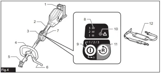
► Fig.4
| 1 | Battery cartridge | 2 | Lock-off lever | 3 | Hanger | 4 | Handle |
| 5 | Release button | 6 | Barrier | 7 | Switch trigger | 8 | Speed indicator |
| 9 | Main power button | 10 | Caution lamp | 11 | Reverse button | 12 | Shoulder harness |
FUNCTIONAL DESCRIPTION
![]() WARNING: Always be sure that the tool is switched off and the battery cartridge is removed before adjusting or checking function on the tool. Failure to switch off and remove the battery cartridge may result in serious personal injury from accidental start-up.
WARNING: Always be sure that the tool is switched off and the battery cartridge is removed before adjusting or checking function on the tool. Failure to switch off and remove the battery cartridge may result in serious personal injury from accidental start-up.
Installing or removing the battery cartridge
![]() CAUTION: Always switch off the tool before installing or removing of the battery cartridge.
CAUTION: Always switch off the tool before installing or removing of the battery cartridge.![]() CAUTION: Hold the tool and the battery cartridge firmly when installing or removing battery cartridge. Failure to hold the tool and the battery cartridge firmly may cause them to slip off your hands and result in damage to the tool and battery cartridge and a personal injury.
CAUTION: Hold the tool and the battery cartridge firmly when installing or removing battery cartridge. Failure to hold the tool and the battery cartridge firmly may cause them to slip off your hands and result in damage to the tool and battery cartridge and a personal injury.
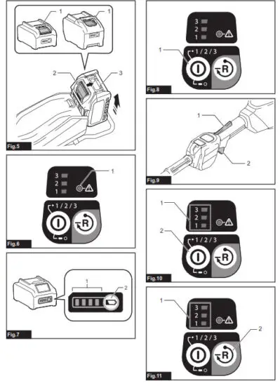
► Fig.5: 1. Red indicator 2. Button 3. Battery cartridge To remove the battery cartridge, slide it from the tool while sliding the button on the front of the cartridge.To install the battery cartridge, align the tongue on the battery cartridge with the groove in the housing and slip it into place. Insert it all the way until it locks in place with a little click. If you can see the red indicator as shown in the figure, it is not locked completely.![]() CAUTION: Always install the battery cartridge fully until the red indicator cannot be seen. If not, it may accidentally fall out of the tool, causing injury to you or someone around you.
CAUTION: Always install the battery cartridge fully until the red indicator cannot be seen. If not, it may accidentally fall out of the tool, causing injury to you or someone around you.![]() CAUTION: Do not install the battery cartridge forcibly. If the cartridge does not slide in easily, it is not being inserted correctly.
CAUTION: Do not install the battery cartridge forcibly. If the cartridge does not slide in easily, it is not being inserted correctly.
Tool/battery protection system
The tool is equipped with a tool/battery protection system. This system automatically cuts off power to the motor to extend tool and battery life. The tool will automatically stop during operation if the tool is placed under one of the following conditions:
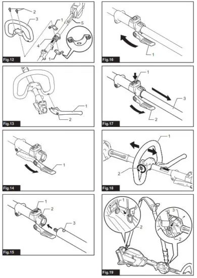
► Fig.6: 1. Caution lamp
| Caution lamp | Status | ||
| Color |  |  | |
| Green |  | Overload | |
| Red |  | Overheat | |
| Red | | Over discharge | |
Overload protection
If the tool or battery gets into one of the following situation, the tool automatically stops and the caution lamp starts blinking in green:
— The tool is overloaded by entangled weeds or other debris.
— The cutting tool is locked or kicked back.
— The main power button is turned on while the switch trigger is being pulled. In this situation, release the switch trigger and remove entangled weeds or debris if necessary. After that, pull the switch trigger again to resume.![]() CAUTION: If you need to remove the entan- gled weeds on the tool or release the locked cutting tool, be sure to turn the tool off before you start.
CAUTION: If you need to remove the entan- gled weeds on the tool or release the locked cutting tool, be sure to turn the tool off before you start.
Overheat protection for tool or battery
If the tool or battery cartridge is overheated, the tool stops automatically. When the tool is overheated, the caution lamp lights up in red. When the battery cartridge is overheated, the caution lamp blinks in red. Let the tool and/or battery cool down before turning the tool on again.
Over-discharge protection
When the battery capacity becomes low, the tool stops automatically and the caution lamp starts blinking in red. If the tool does not operate even when the switches are operated, remove the battery cartridge from the tool and charge it.
Indicating the remaining battery capacity
Press the check button on the battery cartridge to indicate the remaining battery capacity. The indicator lamps light up for a few seconds.
► Fig.7:
- Indicator lamps
- Check button
| Indicator lamps | Remaining capacity | ||
 |  |  | |
 | 75% to 100% | ||
 | 50% to 75% | ||
 | 25% to 50% | ||
 | 0% to 25% | ||
 | Charge the battery. | ||
 | The battery may have malfunctioned. | ||
NOTE: Depending on the conditions of use and the ambient temperature, the indication may differ slightly from the actual capacity.
NOTE: The first (far left) indicator lamp will blink when the battery protection system works.
Main power switch
WARNING: Always turn off the main power switch when not in use.
Press the main power button to turn on the tool. To turn off the tool, press and hold the main power button until the speed indicators go off.
► Fig.8: 1. Main power button
NOTE: The caution lamp brinks if the switch trigger is pulled under inoperable conditions. The caution lamp blinks if you turn on the main power switch while holding down the lock-off lever and the switch trigger.
NOTE: This tool employs the auto power-off function. To avoid unintentional start-up, the main power switch will automatically shut down when the switch trigger is not pulled for a certain period after the main power switch is turned on.
Switch action
![]() WARNING: For your safety, this tool is equipped with a lock-off lever which prevents the tool from unintended starting. NEVER use the tool if it runs when you simply pull the switch trigger without pressing the lock-off lever. Return the tool to our authorized service center for proper repairs BEFORE further usage.
WARNING: For your safety, this tool is equipped with a lock-off lever which prevents the tool from unintended starting. NEVER use the tool if it runs when you simply pull the switch trigger without pressing the lock-off lever. Return the tool to our authorized service center for proper repairs BEFORE further usage.![]() WARNING: NEVER tape down or defeat the purpose and function of the lock-off lever.
WARNING: NEVER tape down or defeat the purpose and function of the lock-off lever.![]() CAUTION: Before installing the battery cartridge into the tool, always check to see that the switch trigger actuates properly and returns to the “OFF” position when released.
CAUTION: Before installing the battery cartridge into the tool, always check to see that the switch trigger actuates properly and returns to the “OFF” position when released.![]() CAUTION: Never put your finger on the main power button and switch trigger when carrying the tool. The tool may start unintentionally and cause injury.
CAUTION: Never put your finger on the main power button and switch trigger when carrying the tool. The tool may start unintentionally and cause injury.
NOTICE: Do not pull the switch trigger hard without pressing the lock-off lever. This can cause switch breakage.
To prevent the switch trigger from being accidentally pulled, a lock-off lever is provided.
► Fig.9: 1. Lock-off lever 2. Switch trigger
To start the tool, turn on the main power switch and grasp the handle (the lock-off lever is released by the grasp) and then pull the switch trigger. Tool speed is increased by increasing the pressure on the switch trigger. To stop the tool, release the switch trigger.
Speed adjusting
You can select the tool speed by tapping the main power button. Each time you tap the main power button, the level of speed will change.
► Fig.10: 1. Speed indicator 2. Main power button
| Speed indicator | Mode |
 | High |
 | Medium |
 | Low |
![]() WARNING: Switch off the tool and remove the battery cartridge before you remove entangled weeds or debris which the reverse rotation function can not remove. Failure to switch off and remove the battery cartridge may result in serious personal injury from accidental start-up. This tool has a reverse button to change the direction of rotation. It is only for removing weeds and debris entangled in the tool. To reverse the rotation, tap the reverse button and pull the switch trigger while depressing the lock-off lever when the cutting tool is stopped. The speed indicators start blinking, and the cutting tool rotates in reverse direction when you pull the switch trigger. To return to regular rotation, release the trigger and wait until the cutting tool stops. ► Fig.11: 1. Speed indicator 2. Reverse button
WARNING: Switch off the tool and remove the battery cartridge before you remove entangled weeds or debris which the reverse rotation function can not remove. Failure to switch off and remove the battery cartridge may result in serious personal injury from accidental start-up. This tool has a reverse button to change the direction of rotation. It is only for removing weeds and debris entangled in the tool. To reverse the rotation, tap the reverse button and pull the switch trigger while depressing the lock-off lever when the cutting tool is stopped. The speed indicators start blinking, and the cutting tool rotates in reverse direction when you pull the switch trigger. To return to regular rotation, release the trigger and wait until the cutting tool stops. ► Fig.11: 1. Speed indicator 2. Reverse button
NOTE: During the reverse rotation, the tool operates only for a short period of time and then automatically stops.
NOTE: Once the tool is stopped, the rotation returns to regular direction when you start the tool again.
NOTE: If you tap the reverse button while the cutting tool is still rotating, the tool comes to stop and to be ready for reverse rotation.
Electronic torque control function
The tool electronically detects a sudden drop in the rotation speed which may cause a kickback. In this situation, the tool automatically stops to prevent further rotation of the cutting tool. To restart the tool, release the switch trigger. Clear the cause of the sudden drop in the rotation speed and then turn the tool on.
NOTE: This function is not a preventive measure for kickbacks.
ASSEMBLY
![]() WARNING: Always be sure that the tool is switched off and battery cartridge is removed before carrying out any work on the tool. Failure toswitch off and remove the battery cartridge may result in serious personal injury from accidental start-up.
WARNING: Always be sure that the tool is switched off and battery cartridge is removed before carrying out any work on the tool. Failure toswitch off and remove the battery cartridge may result in serious personal injury from accidental start-up.![]() WARNING: Never start the tool unless it is completely assembled. Operation of the tool in a partially assembled state may result in serious personal injury from accidental start-up.
WARNING: Never start the tool unless it is completely assembled. Operation of the tool in a partially assembled state may result in serious personal injury from accidental start-up.
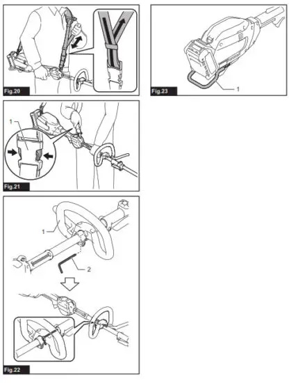
Mounting the handle
Attach the handle with supplied clamps and bolts. Make sure that the handle is located between the spacer and the arrow mark. Do not remove or shrink the spacer.
► Fig.12: 1. Clamp 2. Hex socket bolt 3. Handle
4. Arrow mark 5. Spacer
When using the following attachments, be sure to attach the barrier to the handle using the screw on the barrier.
- Brushcutter attachment *
- Rotary scissors attachment
- Grass trimmer attachment *
- Edger attachment
*. Only when metal blade is attached.
► Fig.13: 1. Barrier 2. Screw
Mounting the attachment pipe
CAUTION: Always check that the attachment pipe is secured after installation. Improper installation may cause the attachment falling off from the power unit and cause personal injury. Mount the attachment pipe to the power unit.
1. Turn the lever of the power unit toward the attachment side.
► Fig.14:
- Lever
- Remove the cap of the attachment. Align the pin with the arrow mark and insert the attachment pipe until the release button pops up.
► Fig.15: 1. Release button 2. Arrow mark 3. Pin - Turn the lever toward the power unit side.
► Fig.16: 1. Lever Make sure that the surface of the lever is parallel to the pipe.
To remove the pipe, turn the lever toward the attachment side and pull the pipe out while pressing down the release button.
► Fig.17:
- Release button
- Lever
- Pipe
Adjusting the handle position
Adjust the handle position to obtain comfortable handling of the tool.
Loosen the hex socket head bolt on the handle. Move the handle to a comfortable working position and then tighten the bolt.
► Fig.18: 1. Handle 2. Hex socket head bolt
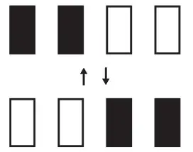
Attaching the shoulder harness![]() WARNING: Be extremely careful to maintain control of the tool at all times. Do not allow the tool to be deflected toward you or anyone in the work vicinity. Failure to keep control of the tool could result in serious injury to the bystander and the operator.
WARNING: Be extremely careful to maintain control of the tool at all times. Do not allow the tool to be deflected toward you or anyone in the work vicinity. Failure to keep control of the tool could result in serious injury to the bystander and the operator.![]() CAUTION: When you use the tool in a combination of the backpack-type power supply such as a portable power pack, do not use the shoulder harness included in the tool package, but use the hanging band recommended by Makita. If you put on the shoulder harness included in the tool package and the shoulder harness of the backpack-type power supply at the same time, removing the tool or backpack-type power supply is difficult in case of an emergency, and it may cause an accident or injury. For the recommended hanging band, ask Makita Authorized Service Centers.
CAUTION: When you use the tool in a combination of the backpack-type power supply such as a portable power pack, do not use the shoulder harness included in the tool package, but use the hanging band recommended by Makita. If you put on the shoulder harness included in the tool package and the shoulder harness of the backpack-type power supply at the same time, removing the tool or backpack-type power supply is difficult in case of an emergency, and it may cause an accident or injury. For the recommended hanging band, ask Makita Authorized Service Centers.![]() CAUTION: Always use the shoulder harness attached to the tool. Before the operation, adjust the shoulder harness according to the user size to prevent fatigue.
CAUTION: Always use the shoulder harness attached to the tool. Before the operation, adjust the shoulder harness according to the user size to prevent fatigue.![]() CAUTION: Before the operation, make sure that the shoulder harness is properly attached to the tool.
CAUTION: Before the operation, make sure that the shoulder harness is properly attached to the tool.
- Clasp the hook on the shoulder harness to tool’s ring and hanger.
► Fig.19: 1. Ring 2. Hook 3. Hanger - Put on the shoulder harness on your left shoulder.
Adjust the shoulder harness to a comfortable working position.
► Fig.20
The shoulder harness features a means of quick release.
Simply squeeze the sides of the buckle to release the tool from the shoulder harness.
► Fig.21: 1. Buckle
Hex wrench storage
CAUTION: Be careful not to leave the hex wrench inserted in the tool head. It may cause injury and/or damage to the tool.
When not in use, store the hex wrench as illustrated to keep it from being lost.
► Fig.22: 1. Handle 2. Hex wrench
MAINTENANCE
![]() WARNING: Always be sure that the tool is switched off and battery cartridge is removed before attempting to perform inspection or maintenance on the tool. Failure to switch off and remove the battery cartridge may result in serious personal injury from accidental start-up.
WARNING: Always be sure that the tool is switched off and battery cartridge is removed before attempting to perform inspection or maintenance on the tool. Failure to switch off and remove the battery cartridge may result in serious personal injury from accidental start-up.
NOTICE: Never use gasoline, benzine, thinner, alcohol or the like. Discoloration, deformation or cracks may result.
To maintain product SAFETY and RELIABILITY, repairs, any other maintenance or adjustment should be performed by Makita Authorized or Factory Service Centers, always using Makita replacement parts.
Cleaning the tool
Clean the tool by wiping off dust, dirt, or cut off grass with a dry cloth or one dipped in soapy water and wrung out. To avoid overheating of the tool, be sure to remove the cut off grass or debris adhered to the vent of the tool.
Battery guard
WARNING: Do not remove the battery guard.
Do not use the tool with the battery guard removed or damaged. Direct impact to the battery cartridge may cause battery malfunction and result in injury and/ or fire. If the battery guard is deformed or damaged, contact your authorized service center for repairs.
► Fig.23: 1. Battery guard
TROUBLESHOOTING
Before asking for repairs, conduct your own inspection first. If you find a problem that is not explained in the manual, do not attempt to dismantle the tool. Instead, ask Makita Authorized Service Centers, always using Makita replacement parts for repairs.
| State of abnormality | Probable cause (malfunction) | Remedy |
| Motor does not run. | Battery cartridge is not installed. | Install the battery cartridge. |
| Battery problem (under voltage) | Recharge the battery. If recharging is not effective, replace battery. | |
| The drive system does not work correctly. | Ask your local authorized service center for repair. | |
| Motor stops running after a little use. | Rotation is in reverse. | Change the direction of rotation with the reversing switch. |
| Battery’s charge level is low. | Recharge the battery. If recharging is not effective, replace battery. | |
| Overheating. | Stop using of tool to allow it to cool down. | |
| It does not reach maximum RPM. | Battery is installed improperly. | Install the battery cartridge as described in this manual. |
| Battery power is dropping. | Recharge the battery. If recharging is not effective, replace battery. | |
| The drive system does not work correctly. | Ask your local authorized service center for repair. |
OPTIONAL ACCESSORIES
![]() CAUTION: These accessories or attachments are recommended for use with your Makita tool specified in this manual. The use of any other accessories or attachments might present a risk of injury to persons. Only use accessory or attachment for its stated purpose. If you need any assistance for more details regarding these accessories, ask your local Makita Service Center. Refer to the “Approved attachment” section for the applicable models for this tool.
CAUTION: These accessories or attachments are recommended for use with your Makita tool specified in this manual. The use of any other accessories or attachments might present a risk of injury to persons. Only use accessory or attachment for its stated purpose. If you need any assistance for more details regarding these accessories, ask your local Makita Service Center. Refer to the “Approved attachment” section for the applicable models for this tool.
- Brushcutter attachment
- String trimmer attachment
- Rotary scissors attachment
- Grass trimmer attachment
- Hedge trimmer attachment
- Ground trimmer attachment
- Pole saw attachment
- Cultivator attachment
- Edger attachment
- Coffee harvester attachment
- Shaft extension attachment
- Power brush attachment
- Power sweep attachment
- Blower attachment
- Makita genuine battery and charger
NOTE: Some items in the list may be included in the tool package as standard accessories. They may iffer from country to country.
Makita Europe N.V.
Jan-Baptist Vinkstraat 2,
Makita Corporation
Anjo, Aichi 446-8502 Japan
3-11-8, Sumiyoshi-cho,
www.makita.com
885830B995
20220219


