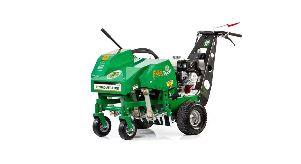
![]() AE1300H Hydro Aerator
AE1300H Hydro Aerator
Instruction Manual
AE1300H
Beginning Serial #: 122020001
Accessories
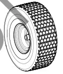
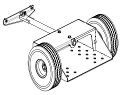
| FOAM TIRES | CHARIOT KIT | SOLID SPIKE TINE | TINE KIT |
| Reduces the chance of flat tires and also adds weight to the machine
| Allows the user to ride behind the unit. Saving fatigue from walking
| Complete set of spike tines for the AE’s arms.
| Individual coring tine for replacement of worn or broken tines.
|
| P/N 362601 | P/N 362609 | P/N 362611 | P/N 360100 |
Original Instructions
IMPORTANT- READ CAREFULLY BEFORE USE AND KEEP FOR FUTURE REFERENCE.
SPECIFICATIONS
| Engine: HP | 13 (9.7 kW) |
| Engine: Model | GX39OUT2X QA2 |
| Engine: Type | Honda |
| Engine: Fuel Capacity | 6.4qt. (6.1 L) |
| Engine: Oil Capacity | 1.16 qt. (1.1 L) |
| Total Unit Weight: | 516# (234 Kg) |
| Max. operating slope | 20° |
SAFETY
![]() WARNING
WARNING ![]()
This product can expose you to chemicals including gasoline engine exhaust, which is known to the State of California to cause cancer, and carbon monoxide, which is known to the State of California to cause birth defects or other reproductive harm. For more information go to www.P65Warnings.ca.gov.
Read the safety rules and follow them closely. Failure to obey these rules could result in loss of control of the unit, severe personal injury or death to you, or bystanders, or damage to property or equipment.
INSTRUCTION LABELS
The labels shown below were installed on your BILLY GOAT® Aerator. If any labels are damaged or missing, replace them before operating this equipment. Part numbers from the Illustrated Parts List are provided for convenience in ordering replacement labels. The correct position for each label may be determined by referring to the part numbers shown.

ENGINE LABELS
- OWNERS MANJ.AL ‘BEFORE OPERATION.
- LE MANUEL U LIT LISAKUR AVANT JSAGE.
- VOR IN BETHIEBNAIVE [ABED’ NGHT BEDIENUNGSANEITUNG DURCIALESEN
- NO tin LEAR SINANTES NO I ..A.BER LEIDO EL MANUAL
HONDA MOTOR CO., LTD. MADE IN JAPAN
HONDA
OIL ALERT
- WHEN OIL LEVEL LOVVit ENGINE STOPS IMMEDIATELY.
IMPORTANT ENGINE IN FORMATiONLIONDA MOTOR CO..LTD ENGINE FAMILY.TNN163U1G 1 RA DISPLACEMENT – 169:m ” TUNE UP SPECIFICATION “REFER TO OWNERS MANUAL FOR MAINTENANCE SPECIFICATIONSANDADJUSTMENTS”. THIS ENGINE E MEETS 1995 CALIFORNIA EMISSION REGULATIONS FOR UTILITY AND LAWN AND GARDEN EQUIPMENT ENGINES.
PACKING CHECKLIST
Your Billy Goat is shipped from the factory in one carton, completely assembled.![]() READ all safety instructions before assembling the unit.
READ all safety instructions before assembling the unit.![]() TAKE CAUTION when removing the unit from the box.
TAKE CAUTION when removing the unit from the box.
PARTS BAG & LITERATURE ASSY
Warranty card P/N- 80102772, Owner’s Manual P/N-362500, General Safety and Warnings Manual Renovation-100295.
Boxing Parts
Checklist
- Owner’s Manual AE1300H 362500
Engine Manual Per Model - Honda 13 HP
ASSEMBLY
- CHECK engine oil level and fill to the proper level.
- CONNECT spark plug wire. Set the engine stop switch to the ON position. You will use the stop switch on the handle during operation.
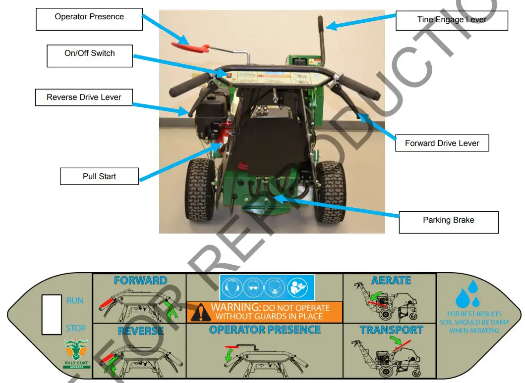
CONTROLS
OPERATION
AERATING OPERATION
NOTE: NEVER PARK THIS UNIT ON A SLOPE OF ANY KIND. Always keep tines in the up position when parking the unit.
TINES RAISING/LOWERING: The tines are raised or lowered into the ground by operating the tine engagement lever on the right of the machine. When engaging the ground, be sure that the lever cams over and locks into place. Tine penetration is very dependent on surface preparation. When removing the tines from the engagement position, make sure the lever fully cams over into the forward position for transport. READ the entire operation section before aerating.
ENGAGE TINES: With the aerator in the work area, lower the tines into the ground with the tine lowering lever and engage the tine lever on the left-hand side of the handle.
SPEED: It is recommended for proper aerating performance that the engine be operated at maximum RPM. Control ground speed using the forward/reverse drive levers. Speed is proportional to the extent the levers are actuated.
AERATE: With the tines engaged, engage either the forward or reverse drive lever for the desired direction of travel. Note:
Core spacing on this machine is determined by speed. The faster you travel the further the spacing between cores pulled and vice versa. NOTE: The hydraulic system may seem sluggish until the oil reaches a normal operating temperature.
PARKING BRAKE: To set the parking brake, push the lever located on the rear of the engine base down and to the right so that it catches. To release the brake, simply push the lever back down and slide it to the left. When the lever is to the right, the parking brake is on. When the lever is to the left the parking brake is off.
TRANSPORT: Be sure to lift the tine engagement lever (tines out of the ground) before transporting away from the work area.
LIFTING AND TIE DOWN: DO NOT Lift this unit. Tie-down points are located on the frame with labels. Always secure the unit at tie-down points before transporting to the job site.
*****TIPS*****
MOW
Mow the lawn to its normal cut height.
WATER
For the best performance and maximum tine penetration, the lawn should be thoroughly watered the day before aeration.
INSPECT
Check the lawn before beginning work. Remove all rocks, wire, string, or other objects that can present a hazard during work prior to starting.
IDENTIFY
Mark all fixed objects to be avoided during work, such as sprinkler heads, water valves, buried cables, or clothesline anchors, etc. Do not operate the aerator on steep slopes. Use extreme caution when operating on any sloped surface. For lesser sloped areas operate the unit, traversing up and down at a 45-degree angle to the slope rather than straight across. Extended operation on steep slopes can cause engine damage. NOTE: DO NOT release the operator’s clutch bail when operating on a slope. This will allow the unit to freewheel and allow the unit to roll down the slope. NOTE: Honda engines are equipped with a low oil sensor to prevent engine damage. When it senses a low oil condition (i.e. unit is operating or sitting on a steep slope) the engine shuts down. The maximum operating slope for the engine is 20. The low oil condition must be corrected before the engine can be restarted. See the engine owner’s manual for more information.
MAINTENANCE
PERIODIC MAINTENANCE
Periodic maintenance should be performed at the following intervals:
| Maintenance Operation | Every Use (daily) | Every 10 hrs | Every 25 hrs | Every 50 Hours |
| Inspect for worn or damaged parts | • | |||
| Check for loose parts | • | |||
| Check engine oil | • | |||
| Thoroughly clean all debris from the unit and tine arms | • | |||
| Oil chains (see lubrication) | • | |||
| Lubricate speed control cables and linkage | • | |||
| Lubricate clutch control cable and linkage | • | |||
| Check Hydraulic oil | • | |||
| Grease front caster assemblies | • | |||
| Inspect the belt for wear | • | |||
| Check rear tire pressure | • |
FOR INFORMATION REGARDING SERVICE INTERVALS FOR THE ENGINE, REFER TO SUPPLIED ENGINE MANUAL ENGINE MUST BE LEVEL WHEN CHECKING OR FILLING THE OIL
SERVICING HYDRAULIC SYSTEM
NOTE: DO NOT SERVICE THE HYDRAULIC SYSTEM WHEN IT IS HOT.
WARNING: Due to the dangerous potential of fluid injection, you should always use a piece of paper to check for hydraulic leaks rather than using your fingers.
![]() READ all safety instructions before servicing the unit.
READ all safety instructions before servicing the unit.![]() DISCONNECT spark plug wire before servicing unit
DISCONNECT spark plug wire before servicing unit
- To check the hydraulic oil level, twist the breather cap on the oil tank counter-clockwise ¼ turn and remove. When looking inside the filler hole, you should fill the tank so that you can just see oil start to cover the bottom of the internal strainer. Use 20W-50 engine oil for normal operating temperatures and for colder climates switch to 15W-40. An excellent choice for colder climates is Mobil 10W-40 Synthetic oil. Overfilling the tank will result in excess oil sloshing out of the breather during operation.
- To change the oil filter it is advisable to clamp the hose from the tank prior to loosening the filter in order to prevent excessive spilling of hydraulic oil.
- Remove the filter by un-screwing counter-clockwise from the filter base.
- When replacing the filter (Billy goat P/N 362396), it is recommended to spread a thin coat of oil on the rubber gasket of the filter prior to re-installing.
- After the rubber gasket seats, turn an additional 2/3 turn.
See page 22 for Hydraulic Schematic.
NOTE: Items in ( ) can be referenced in the Parts Illustrations and Parts Lists on pages 12-23.
INDIVIDUAL TINE REPLACEMENT (See pages 14 and 15 for Parts Illustration and Parts list)
- While it is possible to replace only one tine at a time, it is recommended to replace tines in pairs on a tining arm.
- To replace tines, simply remove the 3/8” bolt that passes through the tining arm assembly. In this way, the tines can be removed from the arm by sliding outward from the tining arm.
- Remove the worn or broken tines from the assembly.
- Inspect the bolt for wear, straightness, or thread damage. If the bolt is damaged, it should be replaced. This bolt is a Grade 8 fastener. Replacing with a weaker bolt is not recommended.
- To re-install, place a washer on the tin holder and then a time onto the bolt. Now install these onto the tining arm with the open side of the line facing the rear of the machine. Once the bolt is through the tining arm, place another time on the bolt, then a tine holder. Finally, install a washer and nylon inserted lock nut. Tighten the assembly.
Be careful not to over-tighten which will bend the tine holders.
NOTE: Tines are a normal wear item and should be inspected regularly for signs of wear or damage.
BELT AND CHAIN TENSION ADJUSTMENT
![]() READ all safety instructions before servicing the unit.
READ all safety instructions before servicing the unit.![]() DISCONNECT spark plug wire before servicing the unit.
DISCONNECT spark plug wire before servicing the unit.
ADJUSTING BELT TENSION (See pages 12 and 13 for Parts Illustration and Parts list)
- Proper belt tension needs to be maintained to prevent slippage during operation. When bail has fully actuated the length of the coiled portion of the clutch cable spring should be 1.75”.
- If the clutch cable spring needs adjustment, loosen the jam nuts holding the cable on the handle assembly and adjust the cable either in or out to shorten or lengthen the spring.
- Once the proper adjustment is reached, tighten the jam nuts.
- Once the adjustment is made, re-install the spark plug wire and test the adjustment. The machine hydraulic pump and transaxle should disengage when the bail is released. There should be no evidence of belt slippage (reduced ground speed or slow time RPM) when operating the machine with bail engaged.
NOTE: Never release the clutch on a slope. The unit is heavy and will free wheel downhill.
NOTE: A worn belt will not allow for proper adjustment and must be replaced.
ADJUSTING CHAIN TENSION (See pages 14 and 15 for Parts Illustration and Parts list)
- Remove the hood (item 4) by removing the seven bolts, washers, and lock washers. (items 111,119,128), that secure it to the tining frame.
- Locate the bolt (items 31, 33) and nut (item 80) that hold each chain idler sprocket to the tining frame of the unit. One idler sprocket sets tension on the left time drive chain and one sets tension on the right time drive chain.
- Loosen the bolt and nut and slide the idler sprocket (item 29) in the desired direction.
INCREASED TENSION: Slide the sprocket up.
DECREASED TENSION: Slide the idler sprocket down. - Tighten the bolt and nut to secure the sprocket in place.
- Replace the hood and reinstall the seven bolts, washers, and lock washers that secure it in place.
NOTE: Over-tensioning the chain will cause premature chain and sprocket wear. DO NOT OVER-TENSION THE CHAIN.
A properly tensioned chain will have a slack of 3/8″-1/2″ when moved by hand.
DRIVE BELT REPLACEMENT (See pages 12 and 13 for Parts Illustration and Parts list)![]() READ all safety instructions before servicing the unit.
READ all safety instructions before servicing the unit.![]() DISCONNECT spark plug wire before servicing the unit.
DISCONNECT spark plug wire before servicing the unit.
- Disconnect the spark plug wire.
- Loosen four screws (item 112) holding the belt cover (item 10) and remove the cover.
- Examine the condition of the belt. Look for cracks, splits, delamination, or damage to the outer covering. Any of these things might warrant replacement.
- If the idler is not providing enough tension inspect the clutch cable spring (item 231) underneath the handle. This spring body should stretch to a length of 1.75” when the operator presence handle is actuated. If not enough tension is being put on the spring this could mean a stretched belt, but most likely the cable needs to be adjusted. Simply loosen the jam nuts holding the cable on the handle assembly and adjust the cable either in or out to shorten or lengthen the spring. Re-tighten nuts and check spring stretch.
- Replace the belt cover (item 10) and secure it with the screws removed earlier.
- Reconnect the spark plug wire.
- Check belt tension by operating the unit under conditions that caused belt slippage. If the belt continues to slip it may require replacement before the operation may continue.
CHAIN REPLACEMENT (See pages 14 and 15 for Parts Illustration and Parts list)
- Remove the hood (item 4) by removing the seven bolts, washers, and lock washers. (items 111,119,128), that secure it to the tining frame.
- Locate the bolt (items 31, 33) and nut (item 80) that hold each chain idler sprocket to the tining frame of the unit.
One idler sprocket sets tension on the left time drive chain and one sets tension on the right time drive chain. - Loosen the bolt and nut and slide the idler sprocket (item 29) to the bottom of the slot in the bracket.
- Locate the master link in the chain and remove it.
- When installing a new chain make sure that the inner crank arm is lined up with the inner crank arm of the opposite side. In operation, the two inner tining arms move together and the two outer tining arms move together. Any other timing of the arms will result in the unsatisfactory performance of the machine.
- Once the new chain is installed, replace the hood and reinstall the seven bolts, washers, and lock washers that secure it in place.
NOTE: Over-tensioning the chain will cause premature chain and sprocket wear. DO NOT OVER TENSION THE
CHAIN. A properly tensioned chain will have a slack of 3/8″-1/2″ when moved by hand.
CHAIN LUBRICATION (See pages 14 and 15 for Parts Illustration and Parts list)
- Remove the top guard by removing the four nuts, two on each side that secure it to the frame.
- Apply a light coat of No. 30 Oil or a penetrating chain lubricant to keep the chain clean and in good running order.
- Replace the guard and reinstall the four screws that secure it in place.
NOTE: If the machine is cleaned with a pressure washer the chains should be lubricated after each cleaning.
TROUBLESHOOTING
| Problem | Possible Cause | Solution |
| The engine will not start | Stop switching off (Honda only). Throttle in off position. The engine is not in the full choke position. Out gasoline. of gasoline. Bad or old gasoline. The spark plug wire disconnected. Dirty air cleaner. Engine oil level too low (Honda only). | Check stop switches, throttle, and choke position I an Connect spark plug wire. Cle. replace air cleaner. Or contact a qualified: service person. Check and fill the engine oil. |
| Abnormal vibration | Damaged or missing tines. Loose handle bolts. Loose engine bolts. | Stop work immediately. Re ce damaged or missing tines. Tighten all loose bo and nuts. |
| Engine stalls or labor when aerating | Working on too steep of a slope. Not enough oil in the engine. Hydraulic oil not up to operating temperature | Work at 45 degrees to the slop moving up and down instead of across. Check and adds engine oil. Allow for hydraulic oil to rea operating temperature |
| The engine is locked, and will not pull over | Debris locked against reel, or drive pulleys. Engine problem. | Pull the spark plug wire and remove debris. Contact an engine servicing dealer for engine problems. |
| The unit does not move when the clutch is engaged | Belt drive out of adjustment. Worn drive belt. Loose or damaged chains or sprockets. Loose or damaged pulleys. Damaged or broken clutch cable. Transmission bypass set in free-wheel | See maintenance on pg. 8 of this manual. Contact a qualified servicing dealer. Set transmission bypass in drive |
When servicing the engine refer to the specific manufacturer’s engine owner’s manual. All engine warranty is covered by the specific engine manufacturer. If your engine requires a warranty or other repair work contact your local servicing engine dealer. When contacting a dealer for service it is a good idea to have your engine model number available for reference (See table page 3). If you cannot locate a servicing dealer in your area you can contact the manufacturer’s national service organization.
To reach:
American Honda: 800-426-7701
WARRANTY CLAIM PROCEDURE
Should a BILLY GOAT® machine fails due to a defect in material and/or workmanship, the owner should make a warranty claim as follows:
- The machine must be taken to the dealer from whom it was purchased or to an authorized Servicing BILLY GOAT Dealer.
- The owner must present the remaining half of the Warranty Registration Card, or, if this is not available, the invoice or receipt.
- The Warranty Claim will be completed by the authorized BILLY GOAT Dealer and submitted to their respective BILLY GOAT Distributor for their territory Attention: Service Manager. Any parts replaced under warranty must be tagged and retained for 90 days. The model number and a serial number of the unit must be stated in the Warranty Claim.
- The distributor service manager will sign off on the claim and submit it to BILLY GOAT for consideration.
- The Technical Service Department at BILLY GOAT will study the claim and may request parts to be returned for examination. BILLY GOAT will notify their conclusions to the distributor service manager from whom the claim was received.
- The decision by the Technical Service Department at BILLY GOAT to approve or reject a Warranty Claim is final and binding.
Make sure that the product is registered with Billy Goat. For online product, registration go to www.billygoat.com
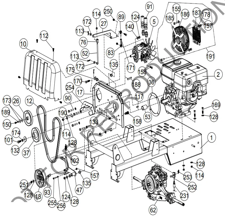
AE1300H PARTS DRAWING ENGINE
 AE1300H PARTS LIST ENGINE
 AE1300H PARTS LIST ENGINE
Item No. | Part No. | Description | Qty |
| 1 | 362602 | ENGINE BASE WA | 1 |
| 2 | 430702 | ENGINE 13 HP HONDA GX390UT2X QA2 | 1 |
| 5 | 362225 | PUMP PK 12cc VARIABLE DISPLACEMENT | 1 |
| 10 | 362327 | GUARD BELT AE900 | 1 |
| 12 | 362337 | BELT HP GP AMD EFF. LENGTH 64.04″ | 1 |
| 17 | 362111 | PLATE PUMP MOUNT | 1 |
| 18 | 362275 | PULLEY 5.00″ OD FLAT IDLER | 1 |
| 26 | 362303 | PULLEY 4.75 OD X .591 ID 5L | 1 |
| 27 | 362116 | ARM ENGAGE PUMP WA | 1 |
| 36 | 812238 | SPACER ENGINE WA DL18 | 1 |
| 37 | 362391 | PULLEY 4.50″ OD X 1.00 ID 5L | 1 |
| 47 | 362112 | IDLER ARM WA AE900 | 1 |
| 52 | 362372 | ROD PUMP ENGAGE | 1 |
| 53 | 362406 | SPACER ENGINE CRANKSHAFT | 1 |
| 62 | 362332 | TRANSAXLE AE900 | 1 |
| 76 | 362280 | END ROD SLIDING | 1 |
| 83 | 351278 | SPHERICAL ROD END MSF-5 | 1 |
| 89 | 351277 | SPHERICAL ROD END MSM-5 | 1 |
| 90 | 8041054 | SCREWCAP 3/8″-16 X 2″ HCS ZP | 4 |
| 91 | 362279 | HOSE HYDRAULIC W#10 JIC | 2 |
| 93 | 362415 | SPACER .75 OD X 11 GA | 1 |
| 101 | 510213 | SCREWCAP 7/16″ – 20 X 1″ HCS GR 8 W/PATCH | 1 |
| 102 | 800242 | SPRING EXTENSION | 1 |
| 112 | 890359 | SCREW SELF-TAP 1/4″-20 X 5/8″ HWH TYPE F | 6 |
| 113 | 900471 | PIN HAIR 1/4″ ZP | 3 |
| 114 | 8160002 | NUT LOCK 5/16″-18 HEX ZP | 9 |
| 117 | 9201113 | KEY 1/4″ SQ X 1.00″ | 1 |
| 124 | 8160003 | NUT LOCK 3/8″-16 | 3 |
| 128 | 8171003 | WASHER 5/16″ FLAT ZP | 12 |
| 132 | 440153 | WASHER 1.5″ OD X .453 ID X .25″ THK | 1 |
| 133 | 8177012 | WASHER LOCK 3/8″ S/T MED | 4 |
| 135 | 362254 | BUSHING .500″ ID | 4 |
| 140 | 8172009 | WASHER 3/8″ SAE | 2 |
| 150 | 370128 | SCREWCAP M6 X 14 | 1 |
| 155 | 8041004 | SCREWCAP 1/4″ – 20 X 3/4″ GR 5 HCS ZP | 8 |
| 157 | 8160001 | NUT LOCK 1/4″-20 HEX ZP | 9 |
| 158 | 8041028 | SCREWCAP 5/16″ – 18 X 1″ GR 5 HCS ZP | 4 |
| 169 | 8041031 | SCREWCAP 5/16″ – 18 X 1 3/4″ GR 5 HCS ZP | 4 |
| 170 | 8041052 | SCREWCAP 3/8″ – 16 X 1 1/2″ HCS ZP | 2 |
| 171 | 8142002 | NUT 5/16″-18 HEX ZP | 1 |
| 172 | 8171002 | WASHER 1/4″ FLAT ZP | 6 |
| 173 | 8172019 | WASHER FLAT FENDER 1/4″ | 2 |
| 174 | 8177013 | WASHER LOCK 7/16″ S/T MED | 1 |
| 175 | 900230 | WASHER 1/2″ FLAT KD WHEEL MTG | 1 |
| 178 | 8172007 | WASHER 1/4″ SAE | 13 |
| 185 | 362330 | BRACKET GUARD FAN | 1 |
| 186 | 362331 | GUARD WIRE PUMP FAN | 1 |
| 187 | 362325 | COOLER OIL | 1 |
| 188 | 362380 | KEY FEATHER 5MM X 5MM X 30MM | 1 |
| 189 | 370120 | WASHER SPLIT M6 | 2 |
| 190 | 370120 | BELT FINGER AE900 | 2 |
| 191 | 362351 | KIT FAN GUARD | 1 |
| 231 | 362276 | CABLE CLUTCH BELT AE900 | 1 |
| 250 | 8161041 | NUT LOCK 5/16″-18 LT WT TH ZP | 1 |
| 251 | 8161042 | NUT LOCK 3/8″-16 LT WT TH ZP | 1 |
| 252 | 440124 | PIN CLEVIS 0.25 X 0.50 | 1 |
| 253 | 371275 | 1/4″ RUE RING | 1 |
| 254 | 862318 | BRACKET BELT GUILD UPPER | 1 |
| 255 | 8041010 | SCREWCAP 1/4″-20 X 2″ HCS ZP | 1 |
| 256 | 900455 | NUT WHIZ 1/4″-20 WASH FACE | 1 |
AE1300H PARTS DRAWING TINE
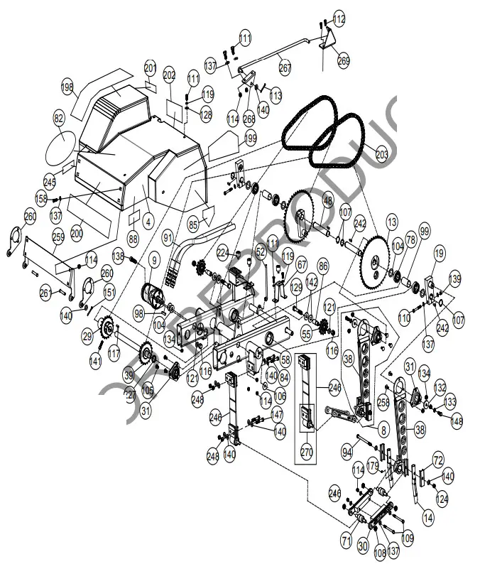
AE1300H PARTS LIST TINE
| Item No. | Part No. | Description | Qty |
| 4 | 362605 | HOOD AE900 | 1 |
| 8 | 362606 | TINE ARM ASSY R IGHT AE900H SERVICE | 2 |
| 362603 | TINE ARM ASSY LEFT AE900H SERVICE | 2 | |
| 9 | 362233 | MOTOR TINE DRIVE | 1 |
| 13 | 362104 | CRANK DRIVING WAAE900 | 2 |
| 14 | 360100 | TINE CORING 3/4 | 8 |
| 19 | 362103-PAINT | ARM CRANK WA AE900 | 2 |
| 29 | 362117 | SPROCKET DIME AE900 | 1 |
| 30 | 362382 | LINK CAST AE1300H | 8 |
| 31 | 362243 | BEARING AND FLAN GETTE ASSY 1.00 | 5 |
| 38 | 362148 | TINE ARM WA | 1 |
| 39 | 362105 | SHAFT DRIVE TINE WA AE900 | 1 |
| 48 | 362227 | SHAFT CRANK AE900 | 2 |
| 52 | 362372 | ROD PUMP ENGAGE | 1 |
| 55 | 362261 | SPROCKET 13T #50 IDLER | 2 |
| 58 | 362101 | FRAME TINING AE900 | 1 |
| 67 | 362282 | BRACKET REM HOOD | 1 |
| 70 | 362281 | BRACKET FRONT HOOD MOUNT | 2 |
| 71 | 362220 | BEARING AND SHAFT | 8 |
| 72 | 362407 | HOLDER TINE AE900 | 16 |
| 78 | 501302 | BEARING 1″ SEALED PRESS IN | 2 |
| 82 | 430303 | LABEL PRODUCT DECAL LG CIRCLE | 1 |
| 84 | 790167 | SCREWCAP 3/8″-24 X2 3/4″ GR 8 W/PATCH | 8 |
| 85 | 400424 | LABEL WARNING OPE I | 2 |
| 86 | 360124 | SPACER TINE IDLER 1.175″ | 2 |
| 88 | 900327 | LABEL WARNING DANGER | 2 |
| 91 | 362279 | HOSE HYDRAULIC W#10 JIC | 2 |
| 94 | 362232 | SCREWCAP 3/8•16 X5 3/4″ GR 8 Arr | 4 |
| 98 | 362288 | KEY#15 HI PRO 116E. | 1 |
| 99 | 362246 | SPACER SPINDLE BEARING | 6 |
| 104 | 362205 | MACHINE BUSHING 1″ X1 1/2014 GAB | 9 |
| 105 | 8024039 | CARRIAGE BOLT 5/16″ – 19’X. ..” ZOO* | 9 |
| 106 | 362284 | WASHER ADHESIVE-BACKED ISOLATION | 7 |
| Item No. | Part No. | Description | Qty |
| 107 | 362212 | RING RETAINING EXTERNAL 1.00″ | 4 |
| 108 | 610305 | NUT LOCK 1/2″ – 20 THIN | 16 |
| 109 | 8041039 | SCREWCAP 5/16″-18 X 4″” HCS ZP | 8 |
| 110 | 831272 | SCREWCAP 5/16″- 24 X 2 1/4″ GR 8 W/PATCH | 4 |
| 111 | 8041026 | SCREWCAP 5/16″-18 X 3/4″ GR 5 HCS ZP | 5 |
| 112 | 890359 | SCREWCAP SELF TAP 1/4″-20 X 5/8″ HWH TYPE F | 2 |
| 113 | 900471 | PIN HAIR 1/4″ ZP | 1 |
| 114 | 8160002 | NUT LOCK 5/16″-18 HEX ZP | 14 |
| 116 | 8160005 | NUT LOCK 1/2″-13 HEX | 4 |
| 117 | 9201113 | KEY 1/4″ SQ X 1.00″ | 5 |
| 119 | 8177011 | WASHER LOCK 5/16″ S/T MED | 11 |
| 121 | 8172011 | WASHER 1/2″ SAE ZP | 4 |
| 124 | 8160003 | NUT LOCK 3/8″-16 | 4 |
| 128 | 8171003 | WASHER 5/16″ FLAT | 7 |
| 129 | 8041102 | SCREWCAP 1/2″-13 X 3″ HCS ZP | 2 |
| 132 | 440153 | WASHER 1.5″ OD X .453 ID X .25″ THK | 4 |
| 133 | 8177012 | WASHER LOCK 3/8″ S/T MED | 4 |
| 134 | 350346 | NUT 5/16″-18 SER HEX FLNG ZP | 18 |
| 137 | 8172008 | WASHER 5/16″ SAE ZP | 40 |
| 138 | 362278 | SHCS 1/2″-13 X 1.750″ ZP | 2 |
| 139 | 81490024 | NUT LOCK 5/16″ – 24 FIN HEX ZP | 4 |
| 140 | 8172009 | WASHER 3/8″ SAE | 9 |
| 141 | 362289 | SHCS 5/16″-18X 1.25 BLK OX | 1 |
| 142 | 8171006 | WASHER 1/2″ USS | 4 |
| 147 | 810932 | SCREWCAP 3/8″-24 X 2 1/4″ GR 8 W/PATCH | 8 |
| 148 | 900154 | SCREWCAP 3/8″ – 24 X 1″ HCS GR 8 | 4 |
| 151 | 8197031 | PIN COTTER 1/8″ X 1″ ZP | 2 |
| 158 | 8041028 | SCREWCAP 5/16″-18 X 1″ GR 5 HCS ZP | 4 |
| 198 | 362504 | LABEL BADGING RISER | 1 |
| 199 | 362502 | LABEL BADGING SIDE | 2 |
| 200 | 362503 | LABEL BADGING FRONT | 1 |
| 201 | 362506 | LABEL WARNING HIGH PRESSURE | 1 |
| 202 | 362507 | LABEL INSTRUCTION HYDRAULIC | 1 |
| 203 | 362258 | CHAIN #50 X 70 PITCHES 0-RING | 2 |
| 224 | 400173 | VIBRATION MOUNT | 5 |
| 227 | 362416 | SPACER 1.25 OD X 1.010 ID .258 LONG | 1 |
| 242 | 9201109 | KEY 1/4″ SQ X 0.75″ | 4 |
| 243 | 362323 | NUT LOCK 3/8″-24 HEX ZP | 16 |
| 245 | 100258 | LABEL HOT SURFACE | 1 |
| 246 | 362607 | SPRING ASSY AE900H | 4 |
| 248 | 362323 | NUT LOCK 3/8-24 | 16 |
| 258 | 362362 | BOLT CARRIAGE 5/16″-18 X 1″ ZP SHRT NK | 12 |
| 259 | 362143 | HOOD BRACKET FRONT AED | 1 |
| 260 | 362142 | HOOD HINGE AEH | 2 |
| 261 | 381716 | PIN CLEVIS 3/8″ X 2″ STAINLESS STEEL | 2 |
| 267 | 362393 | HOOD LIFT ROD | 1 |
| 268 | 362394 | HOOD GUIDE BRACKET UPPER | 1 |
| 269 | 362144 | HOOD GUIDE BRACKET LOWER | 1 |
| 270 | 362613 | SPRING BEARING MOUNT | 1 |
AE1300H PARTS DRAWING DRIVE
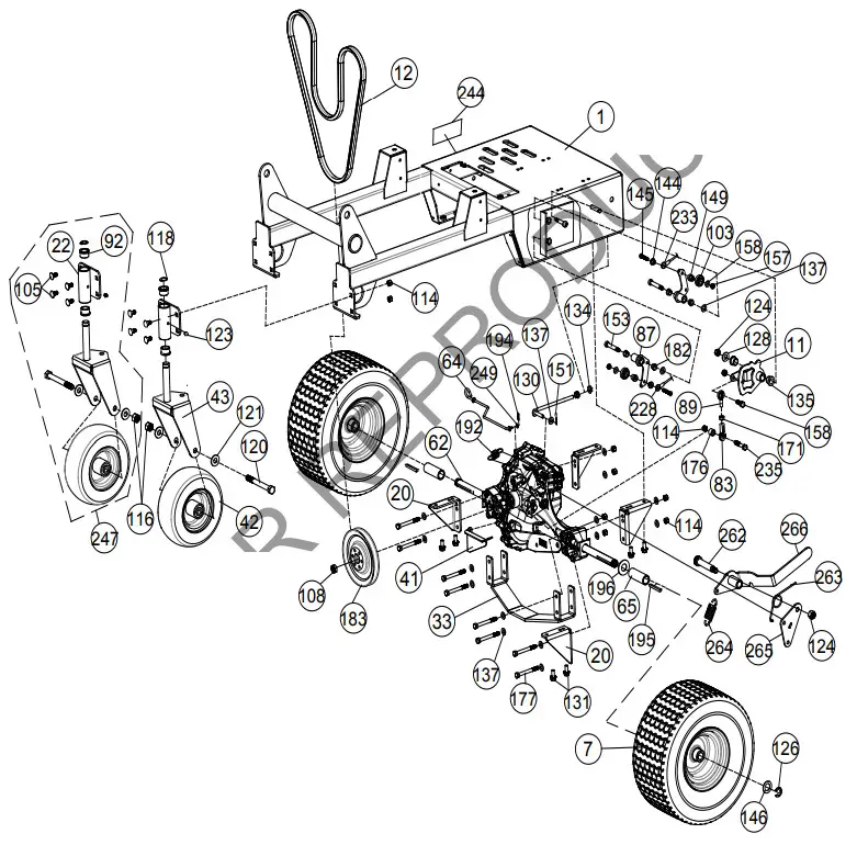
AE1300H PARTS LIST DRIVE
Item No. | Part No. | Description | Qty |
| 1 | 362100 | ENGINE BASE WA | 1 |
| 7 | 362352 | WHEEL 15″ X 6.00 – 6 TURF SAVER | 2 |
| 11 | 362106 | CAM SPEED CONTROL WAS AE900 | 1 |
| 20 | 362329 | BRACKET TRANSAXLE MOUNT | 4 |
| 22 | 362107 | THE BRACKET CASTER WAS AE900 | 1 |
| 33 | 362118 | SKID PLATE WA | 1 |
| 41 | 362306 | BRACKET BELT GUIDE LOWER AE900 | 1 |
| 42 | 373300 | WHEEL, 8″ X 3″ HEAVY-DUTY | 2 |
| 43 | 382125 | WA, CASTER WHEEL | 2 |
| 62 | 362332 | TRANSAXLE AE900 | 1 |
| 64 | 362356 | ROD BYPASS TRANSAXLE | 1 |
| 65 | 362418 | SPACER REAR WHEEL AE900H | 2 |
| 83 | 351278 | SPHERICAL ROD END MSF-5 | 1 |
| 87 | 501114 | BELL CRANK BC2600 WA | 2 |
| 89 | 351277 | SPHERICAL ROD END MSM-5 | 1 |
| 92 | 520184 | BUSHING FLANGE 1″ OD 3/4″ ID | 4 |
| 103 | 351257 | BEARING .500 ID X 1.125 OD X .313 THK | 2 |
| 105 | 8024039 | BOLT CARRIAGE 5/16″ – 18 X 3/4″ ZP | 8 |
| 108 | 610305 | NUT LOCK 1/2″ – 20 THIN | 1 |
| 114 | 8160002 | NUT LOCK 5/16″-18 HEX ZP | 18 |
| 116 | 8160005 | NUT LOCK 1/2″-13 HEX | 2 |
| 118 | 520176 | RING RETAINING EXTERNAL 3/4″ | 2 |
| 120 | 8041108 | SCREWCAP 1/2″ -13 X 4 3/4″ HCS ZP | 2 |
| 121 | 8172011 | WASHER 1/2″ SAE | 4 |
| 123 | 610363 | ZERK GREASE FITTING | 2 |
| 124 | 8160003 | NUT LOCK 3/8″-16 | 7 |
| 126 | 850230 | RETAINING RING E 3/4″ | 2 |
| 128 | 8171003 | WASHER 5/16″ FLAT | 1 |
| 130 | 362341 | ANTI-ROTATION ROD | 1 |
| 131 | 351264 | SER HEX WSHR FLNG SCREW 5/16″-18 X 3/4″ | 8 |
| 134 | 350346 | NUT 5/16″-18 SER HEX FLNG ZP | 2 |
| 135 | 362254 | BUSHING .500″ ID | 2 |
| 137 | 8172008 | WASHER 5/16″ SAE ZP | 17 |
| 144 | 351348 | SPACER SPEED CONTROL EYELET | 2 |
| 145 | 8041008 | SCREWCAP 1/4″-20 X 1 1/2″ HCS ZP | 2 |
| 146 | 850238 | WASHER .765″ ID X 1.25″ OD X .06″ | 2 |
| 149 | 351347 | SPACER SPEED CONTROL STEPPED | 2 |
| 151 | 8197031 | PIN COTTER 1/8″ X 1″ ZP | 1 |
| 153 | 351258 | BOLT SHOULDER 3/8″ X 1 3/4″ | 2 |
| 157 | 8161040 | NUT LOCK 1/4″-20 LT WT TH ZP | 2 |
| 158 | 8041028 | SCREWCAP 5/16″ – 18 X 1″ GR 5 HCS ZP | 1 |
| 171 | 8142002 | NUT 5/16″-24 HEX ZP | 1 |
| 176 | 351419 | SPACER ENGINE SIDE | 1 |
| 177 | 8041036 | SCREWCAP 5/16″-18 X 3″ GR 5 HCS ZP | 8 |
| 182 | 840078 | BUSHING 3/8″ ID X 1/2″ OD X 3/8″ LONG | 4 |
| 183 | 362398 | PULLEY DIA. 6.00 CUPPED 26 TOOTH SPLINE | 1 |
| 192 | 351324 | SPRING TRANSAXLE RETURN | 1 |
| 194 | 440193 | PIN CLIP HITCH 0.051 X 3/4″ | 1 |
| 195 | 9201092 | KEY 3/16″ SQ X 3.00 | 2 |
| 196 | 8172015 | WASHER 3/4″ SAE | 2 |
| 235 | 8041030 | SCREWCAP 5/16″-18 X 1 1/2″ HCS ZP | 2 |
| 244 | 501504 | LABEL DRIVE RELEASE | 1 |
| 247 | 362608 | CASTER ASSY AE900H | 2 |
| 249 | 8172005 | WASHER #10 SAE | 1 |
| 262 | 520031 | BOLT SHOULDER 1/2″ X 2″ | 1 |
| 263 | 510142 | SPRING TRANS IDLER | 1 |
| 264 | 381157 | SPRING EXTENSION 3/4″ OD X 1-3″ | 1 |
| 265 | 362449 | PARKING BRAKE BRACKET | 1 |
| 266 | 362146 | PARKING BRAKE LEVER | 1 |
AE1300H PARTS DRAWING HANDLE
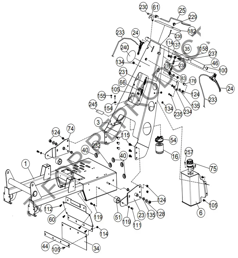
AE1300H PARTS LIST HANDLE
Item No. | Part No. | Description | Qty |
| 1 | 362602 | ENGINE BASE WA | 1 |
| 3 | 362604 | HANDLE WA | 1 |
| 6 | 362134 | TANK OIL WA AE900H | 1 |
| 16 | 362396 | FILTER SPIN ON | 1 |
| 23 | 362119 | BRACKET LH HANDLE MOUNT WA | 1 |
| 24 | 351209 | MAGURA CONTROL | 2 |
| 25 | 362267 | BAIL ASSY AE900 | 1 |
| 34 | 351269 | RUBBER DEFLECTOR | 1 |
| 35 | 362269 | SPHERICAL ROD END FEMALE 5/16″-24 LFT | 1 |
| 40 | 520087 | GROMMET 1″ HOLE | 4 |
| 44 | 351268 | BAR CLAMP DEFLECTOR | 1 |
| 46 | 500267 | GRIP HANDLE 1″ X 5.5″ | 2 |
| 51 | 371210 | RUBBER HANDLE MOUNT | 2 |
| 54 | 362395 | MOUNT OIL FILTER | 1 |
| 60 | 362292 | GUARD TRANSAXLE FRONT | 1 |
| 61 | 362129 | BELL CRANK BAIL WA | 1 |
| 66 | 351200 | BRACKET CLUTCH CABLE OS900SP | 1 |
| 74 | 362120 | THE BRACKET RH HANDLE MOUNT WA | 1 |
| 75 | 362342 | RESERVOIR CAP | 1 |
| 83 | 351278 | SPHERICAL ROD END MSF-F | 1 |
| 100 | 890132 | PLUG TUBE INSERT 1″ OD | 2 |
| 105 | 8024039 | CARRIAGE BOLT 5/16″ – 18 X 3/4″ ZP | 9 |
| 111 | 8041048 | SCREWCAP 3/8″-16 X 3/4″ GR 5 HCS ZP | 4 |
| 112 | 890359 | SCREW SELF-TAP 1/4″-20 X 5/8″ HWH TYPE F | 6 |
| 114 | 8160002 | NUT LOCK 5/16″-18 HEX ZP | 7 |
| 115 | 8024058 | CARRIAGE BOLT 3/8″-16 X 1″ ZP | 6 |
| 119 | 8177011 | WASHER LOCK 5/16″ S/T MED | 4 |
| 124 | 8160003 | NUT LOCK 3/8″-16 | 8 |
| 128 | 8171003 | WASHER 5/16″ FLAT ZP | 2 |
| 134 | 350346 | NUT 5/16″-18 SER HEX FLNG ZP | 5 |
| 135 | 362254 | BUSHING .500″ ID | 4 |
| 137 | 8172008 | WASHER 5/16″ SAE ZP | 2 |
| 154 | 8177010 | WASHER LOCK 1/4″ S/T MED | 2 |
| 155 | 8041002 | SCREWCAP 1/4″ – 20 X 1/2″ HCS ZP | 2 |
| 158 | 8041028 | SCREWCAP 5/16″-18 X 1″ GR 5 HCS ZP | 1 |
| 176 | 351419 | SPACER ENGINE SIDE | 1 |
| 182 | 362501 | LABEL INSTRUCTION AE900H | 1 |
| 229 | 362441 | SWITCH ENGINE KILL TOGGLE | 1 |
| 230 | 360218 | NUT PAL 3/8″ | 1 |
| 231 | 362276 | CABLE CLUTCH BELT AE | 1 |
| 232 | 520092 | GROMMET 1.25″ HOLE | 1 |
| 233 | 362312-S | CABLE SPEED CONTROL ASSY | 2 |
| 234 | 362121 | BELLCRANK CABLE WA | 1 |
| 235 | 8041030 | SCREWCAP 5/16″ – 18 X 1 1/2″ GR 5 HCS ZP | 1 |
| 236 | 362274 | HARNESS WIRE KILL SWITCH | 1 |
| 237 | 362322 | NUT 5/16″-24 LEFT-HAND FIN HEX ZP | 1 |
| 238 | 362266 | JACKSCREW 5/16″-24 RT AND LFT | 1 |
| 239 | 8149002 | NUT 5/16″-24 FIN HEX ZP | 2 |
| 240 | 362505 | LABEL INGROUND TURNING LOGO | 1 |
| 245 | 100258 | LABEL HOT SURFACE | 1 |
| 257 | 8050057 | SHCS 10-32 NF 1/2″ SS | 6 |
AE1300H PARTS DRAWING LIFT
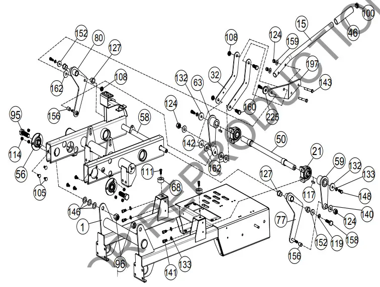
AE1300H PARTS LIST LIFT
| Item No. | Part No. | Description | Qty |
| 1 | 362602 | ENGINE BASE WA | 1 |
| 15 | 362410 | HANDLE TINE WA | 1 |
| 21 | 362223 | BEARING LIFT | 2 |
| 32 | 362259 | BRACKET HANDLE SUPPORT | 2 |
| 46 | 500267 | GRIP HANDLE 1″ X 5.5″ | 1 |
| 50 | 362108 | TINE FRAME LIFT SHAFT WA | 1 |
| 56 | 362245 | BEARING AND FLANGETTE ASSY .75″ | 2 |
| 58 | 362101 | FRAME TINING AE900 | 1 |
| 59 | 362127 | LIFT ARM LFT WA AE900 | 1 |
| 63 | 362125 | ARM LIFT RT WA AE900 | 1 |
| 68 | 360298 | BUMPER RECESS | 2 |
| 77 | 362128 | ARM TINE LIFT CONNECTING WA LH | 1 |
| 80 | 362126 | ARM TINE LIFT CONNECTING WA RH | 1 |
| 95 | 8041166 | SCREWCAP 3/4″ – 10 X 2 1/2″ LG ZP | 2 |
| 96 | 8161006 | NUT LOCK 3/4″ – 10 ZP | 2 |
| 100 | 890132 | PLUG TUBE INSERT 1″ OD | 1 |
| 105 | 8024039 | CARRIAGE BOLT 5/16″ – 18 X 3/4″ ZP | 6 |
| 108 | 610305 | NUT LOCK 1/2″ – 20 THIN | 3 |
| 111 | 8041026 | SCREWCAP 5/16″-18 X 3/4″ GR 5 HCS ZP | 2 |
| 114 | 8160002 | NUT LOCK 5/16″-18 HEX ZP | 6 |
| 117 | 9201113 | KEY 1/4″ SQ X 1.00″ | 8 |
| 119 | 8177011 | WASHER LOCK 5/16″ S/T MED | 2 |
| 124 | 8160003 | NUT LOCK 3/8″-16 | 4 |
| 127 | 360183 | BUSHING PIVOT FRAME AE | 4 |
| 128 | 8171003 | WASHER 5/16″ FLAT ZP | 2 |
| 132 | 440153 | WASHER 1.5″ OD X .453 ID X .25″ THK | 2 |
| 133 | 8177012 | WASHER LOCK 3/8″ S/T MED | 6 |
| 140 | 8172009 | WASHER 3/8″ SAE | 2 |
| 141 | 8049070 | SHCS 5/16″-18 X 1.25 BLK OX | 4 |
| 142 | 8171006 | WASHER 1/2″ USS | 1 |
| 143 | 8041055 | SCREWCAP 3/8″ – 16 X 2 1/4″ HCS ZP | 2 |
| 146 | 850238 | WASHER .765″ ID X 1.25″ OD X .06″ | 2 |
| 148 | 900154 | SCREWCAP 3/8″ – 24 X 1″ HCS GR 8 | 2 |
| 152 | 441150 | WASHER 1.125″ OD X .344″ ID X .25 THK | 2 |
| 156 | 362257 | BUSHING TINE FRAME PIVOT | 2 |
| 158 | 8041028 | SCREWCAP 5/16″ – 18 X 1″ GR 5 HCS ZP | 2 |
| 159 | 8171004 | WASHER 3/8″ FC | 2 |
| 160 | 520028 | SCREWCAP 1/2″ -20 X 1 1/4″ GR 5 W/PATCH | 3 |
| 162 | 362286 | WASHER NYLON | 6 |
| 197 | 362113 | TINE ENGAGE HANDLE MOUNT WA | 1 |
| 225 | 362419 | WASHER 33/64 I.D. X 1.50″ OD X .25 THK | 1 |
AE1300H PARTS DRAWING PUMP
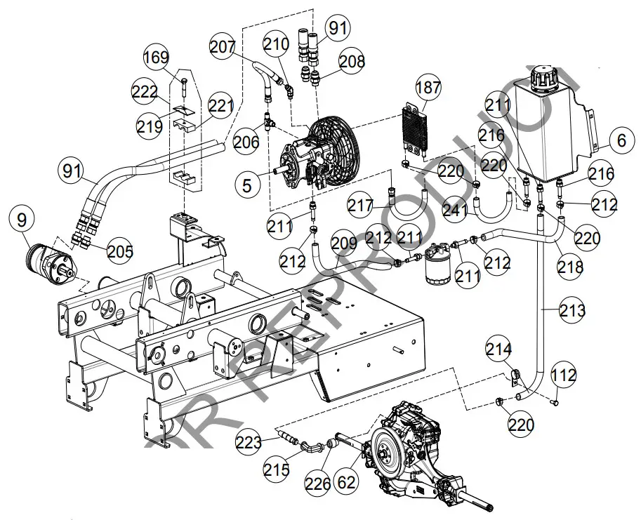
AE1300H PARTS LIST PUMP
Item No. | Part No. | Description | Qty |
| 5 | 362225 | PUMP PK 12cc VARIABLE DISPLACEMENT | 1 |
| 9 | 362233 | MOTOR TINE DRIVE | 1 |
| 91 | 362279 | HOSE HYDRAULIC W#10 JIC | 2 |
| 112 | 890359 | SCREW SELF TAP 1/4″ – 20 X 5/8″ HWH TYPE F | 1 |
| 169 | 8041032 | SCREWCAP 3/8″ – 16 X 1 2″ HCS ZP | 1 |
| 187 | 362325 | COOLER OIL | 1 |
| 205 | 362231 | FITTING 10MJ – 10MOR STR | 1 |
| 206 | 362420 | FITTING TEE 6803-06-06-06 | 1 |
| 207 | 362423 | HOSE ASSY #6 JIC TO RAW 11.00″ LONG | 1 |
| 208 | 362230 | FITTING 10MF 0- 8MORB STRAIGHT | 2 |
| 209 | 362426-S | HOSE, HYDRAULIC 1/2″ X 12.00″ LONG | 1 |
| 210 | 362421 | FITTING 45 DEG 6802-06-04 W/0.050″ ORIFICE | 1 |
| 211 | 362309 | FITTING 08HB – 08MORB STRAIGHT | 4 |
| 212 | 362311 | CLAMP MINIATURE WORM GEAR MAH6 | 4 |
| 213 | 362425 | HOSE HYDRAULIC 3/8″ X 46.00″ LONG | 1 |
| 214 | 790170 | HOSE CLAMP | 1 |
| 215 | 362320 | FITTING 90 DEG FEMALE TO FEMALE | 1 |
| 216 | 362234 | FITTING 06HB – 06MORB STRAIGHT | 2 |
| 217 | 362422 | HOSE ASSY #6 JIC TO RAW 13.00″ LONG | 1 |
| 218 | 362424-S | HOSE HYDRAULIC 3/8″ X 19.00″ LONG | 1 |
| 219 | 362300 | PLATE CLAMP COVER | 1 |
| 220 | 5109783 | CLAMP, MINIATURE WORM GEAR MAH4 | 4 |
| 221 | 362299 | BODY PROFILED CLAMP | 2 |
| 222 | 362013 | HYDRAULIC HOSE CLAMP | 1 |
| 223 | 362321 | 3/8″ HOSE BARB | 1 |
| 226 | 362315 | 04MORB – 02MP STRAIGHT | 1 |
| 241 | 362427-S | HOSE HYDRAULIC 1/2″ 14.00″ LONG | 1 |
![]()


