![]() PAD18 0-10V Dimmer
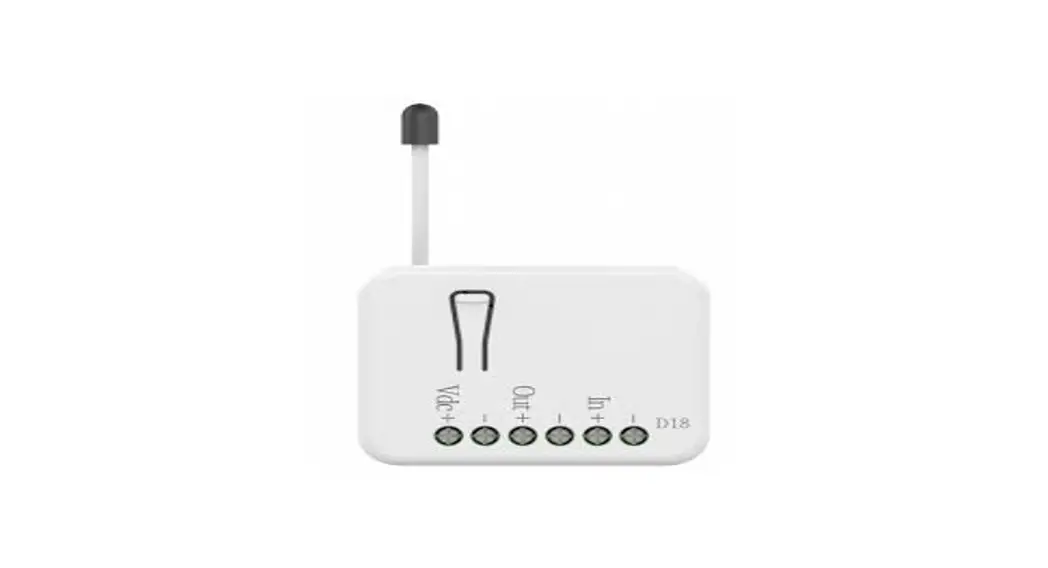
PAD18 0-10V Dimmer
![]()
PAD18 is a 0-10V dimmer.
This device is a security-enabled Z-Wave Plus™ product. The encrypted Z-Wave Plus™ messages support PAD18 to communicate with other Z-Wave Plus™ products.
PAD18 can be used with Z-Wave™ devices (with Z-Wave™ logo) from different manufacturers, it can also be included in the ZWave™ networks from different manufacturers.
All mains operated nodes (even from different manufacturers) in the network act as repeaters to increase the stability and reliability of the Z-Wave™ network.
The product is supported with Over-the-Air (OTA) feature for firmware upgrade.
Specification
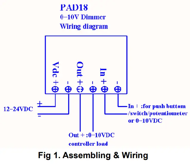
| Rating | 12-24VDC, Max. 70mA. |
| In + | Sensor: 0-10VDC Push-button, Switch Potentiometers 100K |
| Out + | 0-10VDC for controller load |
| RF distance | Min. 40M indoor, 100M outdoor line of sight, |
| RF Frequency | 868.4MH, 869.85MHz (EU) 922.5MHz, 923.9MHz, 926.3MHz (JP) 920.9MHz, 921.7MHz, 923.1MHz (TW/KR/Thai/SG) Transceiver |
| RF Maximum Power (Peak) | +10dBm (Peak) |
| RF Maximum Power (Average) | -10dBm (Average) |
| Dimension | 47.5(L) x 39(W) x 16(H) mm |
| Weight | 30.2g |
| IP classification | IP20; indoor use |
| Operation temperature | -10 to 40° C |
| Humidity | 85%RH max |
| FCC ID | RHHPAD18 |
| Marking | CE/NCC |
- Specifications are subject to change and improvement without notice.
Troubleshooting
| Symptom | Cause of Failure | Recommendation |
| The device can not join to | The device may in a Z- | Exclude the device then |
| Z-Wave™ network | Wave™ network. | include again. |
Installation Steps
- Connect the switch to the In +& -, or potentiometer, or various sensors.
- Connect Out +& – to controller load.
- Connect Vdc +& – to 12-24VDC.
IMPORTANT
Installation must be performed by skilled technicians who are informed about the standards and technical requirements of the appliance and its proper installation. Check your local codes as they apply to your situation. If the house wiring is of aluminum, consult with an electrician about proper wiring methods. Before proceeding with the installation, TURN OFF THE POWER TO THE LIGHTING CIRCUIT AT THE CIRCUIT
BREAKER OR FUSE BOX TO AVOID ELECTRICAL SHOCK.
For Instruction to http://www.philio-tech.com
![]() Danger of Electrocution
Danger of Electrocution
All works on the device may be performed only by a qualified and licensed electrician. Observe national regulations. Any work introducing changes into the configuration must be always performed with disconnected voltage. Choosing a Suitable Location
- Do NOT place the module/device direct under sunlight, in a humid place, or in any location where they may contact with moisture, dirt, or dust.
- Do NOT place the module/device where exists combustible substance or any source of heat, fires, radiators, boiler, etc.
- When the module/device be used, the module/device might get warm. This is a normal condition.
Adding to Z-Wave™ Network
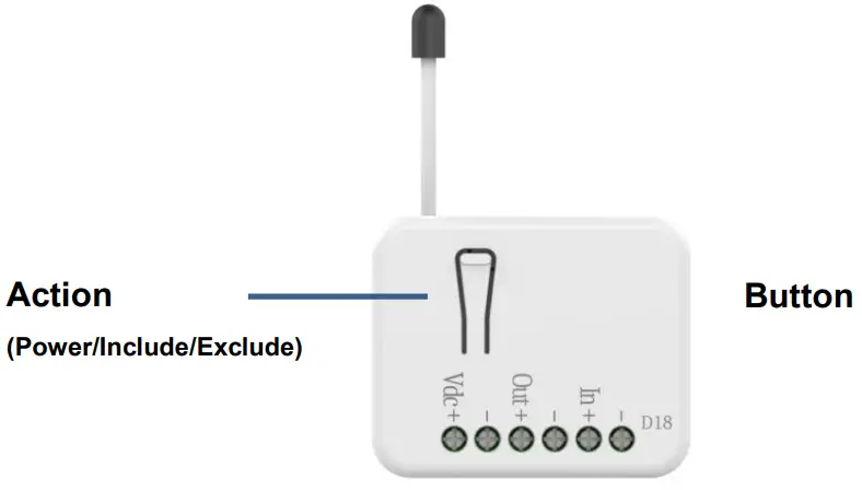
There is a button with LED indicator in front of PAD18. It is used to dim on/off the light and carry out the inclusion, exclusion, reset, or association of PAD18 from Z-wave controller.
When the first power one, the LED indicator flashes once per second for 30 seconds. With the SmartStart function, PAD18 will be automatically included by Z-wave controller. PAD18 can be operated with any certified Z-Wave™ devices from different manufacturers in the Z-Wave™ network. All non-battery operating devices act as repeaters to increase the stability and reliability of the Z-Wave™ network.
The table below provides an operation summary of basic ZWave™ functions. To add/remove/associate PAD18, please refer to the instruction of the certified Z-Wave™ Primary Controller.
| Function | Description | Annotation |
|
Without Node ID | New PAD18 does not have Node ID until it is included by a Z-Wave™ Controller. | LED light flashes once per second for 30 seconds. |
|
Add (Classic Inclusion) | 1. Set Z-Wave™ Controller to inclusion mode by following the instructions provided by the controller manufacturer. 2. Press the button on PAD18 three times within 3 seconds to enter inclusion mode. |
| SmartStart | 1. To initiate the SmartSart process, please type in the first five digits of DSK string or scan the QR code. The QR Code can be found on PAD18 or in the box. Ex: DSK: 18112-24021- 48001-62259-57092-27453-08187-47408 2. PAD18 is supported with SmartStart, it can be added to Z-Wave™ network by scanning the Z-Wave™ QR code on the product. 3. Without further actions, PAD18 will be auto- matically included in a certified Z-Wave™ Controller with SmartStart inclusion ability in 10 minutes after it is turned on. | |
| Remove (Exclusion) | 1. Set your Z-Wave™ controller to exclusion mode by following the instructions provided by the controller manufacturer. 2. Press the button on PAD18 three times within 3 seconds to enter exclusion mode. 3. Node ID will be excluded. | LED light flashes once per second for 30 seconds. |
| Reset | 1. Press the button of PAD18 four times within 3 seconds and hold the last press until the LED light turns off. | LED light turns on. |
| 2. Once the LED light turns off, release the button within 2 seconds. | LED light turns off. | |
| 3. Device has been reset. | LED light flashes once per second for 30 seconds. | |
| ||
LED Light Indication
The LED light indicates the different modes of the PAD18
| State Type | LED Indication |
| Without Node ID | Under normal operation, when the PAD18 has not been allocated a node ID, the LED light will flash on and off alternately at 1-second intervals. By pressing the On/Off button, the LED light will stop flashing temporarily. |
| Learning | Flashes when learning is successful |
Manual Dimming Level Control
- Long press the button, and the light level will be increased and decreased, slowly and repeatedly.
- Short press the button, and the light will be on/off to the last light level.
- User can set Z-Wave™ Configuration 1 according to different switch types as the following form tells:
| Input Switch Type | Config 1 Set Value | Long Press | Short Press |
| Button on PAD 18 | – | Dimming | On / Off |
| General Switch | 0 | Dimming | On / Off |
| Variable Resistor | 1 | Dimming | – |
Z-Wave™ Functions
Basic Command Class and Multilevel Switch Command Class are two parts of the Z-Wave™ system. PAD18 responds to both Basic Command Class and Multilevel Switch Command Class. However, if PAD18 is included as a secure node, it responds only to the security encapsulation command of Basic Command Class and MultilevelSwitch
Command Class.
The Basic Command Class is mapped according to the following table.
| Basic Command | Mapped Command |
| Basic Set (Value) | Multilevel Switch Set (Value) |
| Basic Report (Current Value, Duration) | Multilevel Switch Report (Value, Duration) |
Z-Wave™ Association Groups
PAD18 can be set to send reports to associated Z-Wave™ devices. It supports one association group with five nodes support for group 1.
For group 1, the dimmer will report MULTILEVEL_SWITCH_REPORT SENSOR_MULTILEVEL_REPORT and DEVICE_RESET_LOCALLY_NOTIFICATION.
- Grouping 1 Lifeline (Maximum 5 nodes).
- MULTILEVEL_SWITCH_REPORT When “on” or “off” state has been changed, It will send Multilevel Switch Report to the nodes of Grouping 1.
- SENSOR_MULTILEVEL_REPORT When the sensor is changed exceeds a threshold.
- DEVICE_RESET_LOCALLY_NOTIFICATION When PAD18 is reset manually, it will send DEVICE_RESET_LOCALLY_NOTIFICATION to the nodes of group 1.
Z-Wave™ Configuration
| No. | Name | Size (Byte) | Default | Value | Description (Info) |
| 1 | Input Mode | 1 | 0 | 0~4 | 0: General Switch 1: Variable Resistor 2: Temperature Sensor 3: Brightness Sensor 4: General Sensor |
| 2 | Power-on Recovery Status Config | 1 | 0 | 0~2 | To set dimmer level when DC power on. Setting value: 0: OFF-0% 1: ON to previous level 2: ON-99% |
| 3 | RF Report Config | 1 | 1 | 0~1 | To set if device send Multilevel Switch report to the gateway when dimming finished. Setting value: 1: Report ON 0: Report OFF |
| 4 | Output Max Level | 1 | 99 | Minimum level +1~99 | To set dimming level maximum value. Dimming level will not over the setting value. Setting value: Cannot be lower than the Minimum level |
| 5 | Output Min Level | 1 | 0 | 0~ (Maximum level 1) | To set dimming level minimum value. Dimming level will directly go to 0% when the dimming value is lower than the setting value. Setting value: Cannot be higher than the maximum level |
| 6 | Basic Duration Config | 1 | 2 | 0~127 | Unit: second To set dimming finished duration time when physical switch used. Ex: When the setting is 2, it will take 2 seconds from switch on action to dimming finished. |
| 7 | Auto Dimmer | 1 | 0 | 0~1 | Automatic Dimmer |
| 8 | Auto Off | 1 | 0 | 0~127 | Automatic turning off the output after a set time |
| 9 | Auto On | 1 | 0 | 0~127 | Automatic turning on output after set time |
| 10 | Sensor Sampling Time | 1 | 1 | 1~127 | Sensor sampling time |
| 11 | Max Value Temperature Sensor | 2 | 1000 | (No.12+1) ~32767 | Maximum temperature sensor range value |
| 12 | Min Value Temperature Sensor | 2 | -400 | -32767 ~ (N0.11-1) | Minimum temperature sensor range value |
| 13 | Temperature Offset | 2 | 0 | -32768 ~32767 | Temperature offset settings |
| 14 | Temperature Threshold | 2 | 5 | 1~32767 | Temperature reporting threshold |
| 15 | Max Value Illuminance Sensor | 4 | 10000 | 1~200000 | Maximum Illuminance Sensor range value |
| 16 | Illumination Offset | 4 | 0 | -200000 ~200000 | Illumination offset settings |
| 17 | Illumination Threshold | 4 | 1000 | 1~200000 | Illumination reporting threshold |
| 18 | General Threshold | 1 | 5 | 1~100 | General reporting threshold |
Notice 1: Always Reset a Z-Wave™ device before trying to add it to a Z-Wave™ network.
Notice 2: PAD18 can be operated in any Z-Wave™ network provided by other certified Z-Wave™ Controllers. All non-battery operating devices act as repeaters to increase the stability and reliability of the Z-Wave™ network.
Over-the-Air (OTA) Firmware Update
The device is supported with Z-Wave™ firmware update via OTA.
- Set the Z-Wave™ Controller into the firmware update mode.
- Choose the hex file to update the firmware.
- Wait 10~15 minutes for completing the OTA process.
- Result of OTA will show in Z-Wave™ Controller log.
During the OTA process, please DO NOT remove the power, otherwise, the firmware will be broken, and the device will be nonfunctional.
Z-Wave™ Supported Command Class
| Command Class | Version | Required Security Class |
| Z-Wave Plus™ Info | 2 | None |
| Security | 1 | None |
| Security 2 | 1 | None |
| Supervision | 1 | None |
| Transport Service | 2 | None |
| Association | 2 | Highest granted Security Class |
| Association Group Information | 3 | Highest granted Security Class |
| Device Reset Locally | 1 | Highest granted Security Class |
| Firmware Update Meta Data | 5 | Highest granted Security Class |
| Indicator | 3 | Highest granted Security Class |
| Manufacturer Specific | 2 | Highest granted Security Class |
| Multi-Channel Association | 3 | Highest granted Security Class |
| Powerlevel | 1 | Highest granted Security Class |
| Version | 3 | Highest granted Security Class |
| Configuration | 4 | Highest granted Security Class |
| SENSOR MULTILEVEL | 11 | Highest granted Security Class |
| SWITCH MULTILEVEL | 4 | Highest granted Security Class |
CAUTION
Risk of explosion if the battery is replaced by an incorrect type.
Dispose of used battery according to the instructions. Choosing a Suitable Location
- The suitable ambient temperature for the module/device is 0°C40°C.
- Do NOT place the module/device direct under sunlight, in a humid place, or in any location where they may contact with moisture, dirt, or dust.
- Do NOT place the module/device where exists combustible substances or any source of heat, fires, radiators, boiler, etc.
Disposal
| This marking indicates that this product should not be disposed of with other household wastes throughout the EU. To prevent possible harm to the environment or human health from uncontrolled waste disposal, recycle it responsibly to promote the sustainable reuse of material resources. To return your used device, please use the return and collection systems or contact the retailer where the product was purchased. They can take this product for environmentally safe recycling. |

Philio Technology Corporation
8F., No.653-2, Zhongzheng Rd., Xinzhuang Dist., New Taipei City
24257, Taiwan(R.O.C)
www.philio-tech.com
FCC Interference Statement
This equipment has been tested and found to comply with the limits for a Class B digital device, pursuant to Part 15 of the FCC Rules. These limits are designed to provide reasonable protection against harmful interference in a residential installation. This equipment generates, uses, and can radiate radio frequency energy and, if not installed and used in accordance with the instructions, may cause harmful interference to radio communications. However, there is no guarantee that interference will not occur in a particular installation. If this equipment does cause harmful interference to radio or television reception, which can be determined by turning the equipment off and on, the user is encouraged to try to correct the interference by one of the following measures:
- Reorient or relocate the receiving antenna.
- Increase the separation between the equipment and receiver.
- Connect the equipment into an outlet on a circuit different from that to which the receiver is connected.
- Consult the dealer or an experienced radio/TV technician for help.
This device complies with Part 15 of the FCC Rules. Operation is subject to the following two conditions: 1. This device may not cause harmful interference, and 2. This device must accept any interference received, including interference that may cause undesired operation. FCC Caution: Any changes or modifications not expressly approved by the party responsible for compliance could void the user’s authority to operate this equipment. This transmitter must not be co-located or operating in conjunction with any other antenna or transmitter.


