Antunes IS-8000 Steam and Hold Infini Steam
Safety Information
Installation
- Read and understand all instructions before installing or using the unit.
- The unit MUST be installed by personnel qualified to work with electricity and plumbing.
- Install this unit to comply with the basic plumbing code of the Building Officials and Code Administrators, Inc. (BOCA) and the Food Service Sanitation Manual of the Food and Drug Administration (FDA).
- Install and locate the equipment only for its intended use as described in this manual.
WARNING
ELECTRICAL SHOCK HAZARD. Failure to follow the instructions in this manual could result in serious injury or death. Do not modify the power supply cord plug. If it does not fit the outlet, have a proper outlet installed by a qualified electrician. Electrical ground is required on this appliance. Check with a qualified electrician if you are unsure if the appliance is properly grounded. Do NOT use an extension cord with this product. The unit should be grounded accord-ing to local electrical codes to prevent the possibility of electrical shock. It requires a grounded receptacle with separate electrical lines, protected by fuses or circuit breaker of the proper rating. NEVER unplug the power cord while the unit is running. Use the proper shutdown procedure before unplugging the power cord.
Operation
- The unit is furnished with
- a properly grounded cord connector. Do not attempt to defeat the grounded connector.
- Do not operate the unit if it has been damaged or dropped, if it has a damaged cord or plug, or if it is not working properly.
- Do not block or cover any openings on the equipment.
- Do not immerse the cord, unit, or plug in water.
- Keep the cord away from heated surfaces.
- Do not allow the cord to hang over the edge of a table or counter.
- Keep the area around the unit free and clear of all combustible materials.
- Failure to do so may result in fire or property damage.
- Opening steamer drawers during operation releases steam.
- The compartment and contents may be hot.
Maintenance
- Do not use abrasive materials; they can damage the unit’s stainless steel finish.
- Do not use corrosive chemicals in this equipment.
- Chlorides or phosphates in cleaning agents (e.g., bleach, sanitizers, degreasers, and detergents) can permanently damage stainless steel equipment. The damage is usually in the form of discoloration, dulling of the metal surface finish, pits, voids, holes, or cracks.
- This damage is permanent and is not covered by warranty.
- Always use a soft, damp cloth for cleaning. Rinse with clear water and wipe dry. When required, always rub in the direction of metal polish lines.
- Routine cleaning should be performed daily with soap and water.
- Rub off finger marks and smears using soap and water.
- Do not clean unit or components in a dishwasher unless specifically specified in the cleaning instructions.
- Do not clean the unit with a water jet or steam cleaner.
- When using the citric acid
- leaning solution as prescribed in this manual, follow the recommended manufacturer’s safety precautions. Use gloves and eye protection when required.
Service
- Inspection, testing, and repair of electrical equipment must be performed only by qualified service personnel.
- To avoid possible personal injury and/or damage to the unit, all inspections, tests, and repair of electrical equipment should be performed by qualified personnel ONLY. Contact Antunes Technical Service for adjustment or repair.
- Turn the power off, unplug the power cord, and allow unit to cool to room temperature before performing any service or maintenance.
- If the supply cord is damaged, t must be replaced by the manufacturer, its service agent, or a similarly qualified person in order to avoid an electrical hazard.
- y Cleaning and user maintenance shall not be made by children without supervision.
Specifications
Electrical Ratings
| Model & Mfg. No. | Volts | Watts | Amp | Hertz |
| 9100948 9100949 | 208 | 9000 | 41 | 50/60 |
| Water Requirements Water Quality (Treated Water): | |
| Hardness (Calcium & Magnesium) | 1 GPG Maximum |
| Total Alkalinity | 600 PPM Maximum |
| Total Silica | 150 PPM Maximum |
| Iron Content | 0.1 PPM Maximum |
| pH | 6.5-10.5 |
| Total Dissolved Solids | 2,500 PPM Maximum |
| Oxygen Content | 0 PPM |
| Carbon Dioxide | 0 PPM |
| Water Pressure Requirements | |
| Minimum Water Pressure | 40 psig |
| Maximum Water Pressure | 60 psig |
Electrical Cord & Plugs
| Model & Mfg. No. | Description | Configuration |
| 9100948 9100949 | NEMA 6-50P 250 VAC, 50 AMP or 6 AWG Wires | 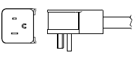
|
IMPORTANT
Failure to follow these water quality conditions will void the warranty and may cause the steamer to operate erratically or fail prematurely and require a service call.
Dimensions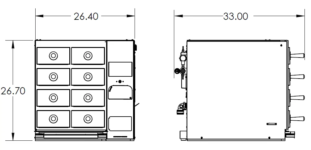
Unpacking
WARNING
This steamer must be installed by personnel who are qualified to work with electricity and plumbing. Improper installation can cause injury to personnel and/or to the equipment. The steamer must be installed in accordance with all applicable codes.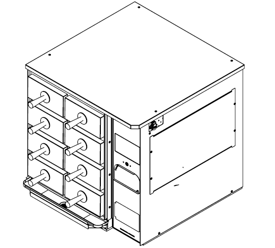
CAUTION
The Steamer has an approximate shipping weight of 260 pounds. For safe handling OBTAIN EXTRA PERSONNEL to properly and safely install the steamer.
WARNING
The installation surface MUST be flat, and the cart, table, or service rack MUST have a rated service weight capacity of 360 pounds per steamer.
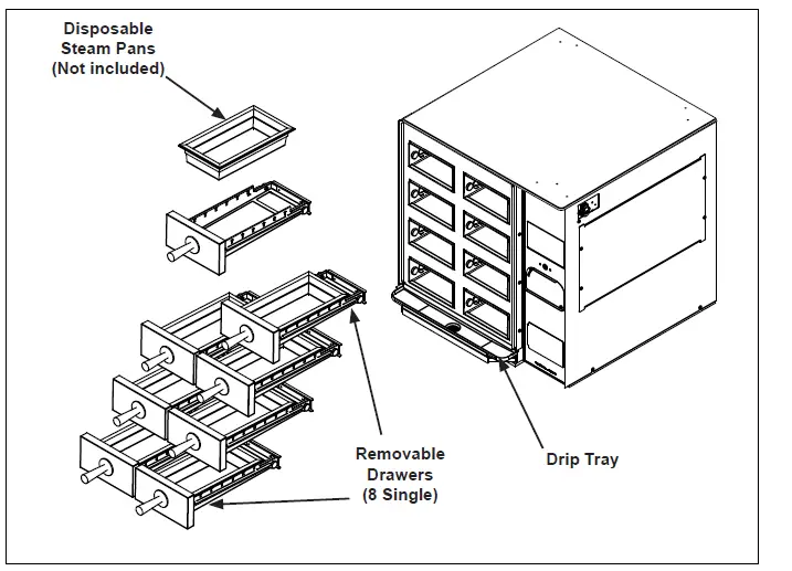
- Remove steamer and all accessories from the packaging.
- Remove all packing materials and protective coverings from the steamer.
- Record the model number, serial number, and installation date of your steamer and keep this information for future reference. Space for this is provided on page 2.
- Wash all removable components in soap and water. Wipe down all exterior surfaces of the steamer with a hot damp cloth.
- Install components onto steamer as shown in Figure 2.

Installation
The steamer should be installed in a well-ventilated room. The steamer must be securely fastened to a table or moveable cart that is capable of handling the weight of one or multiple steamers. Each Steam and Hold weighs approximately 200 pounds and the total weight capacity requirements of the cart or table must be considered prior to installation. 3X safety factor recommended. I.e. 1 Steam and Hold (200 lbs) x 3 S.F. = 600 lbs minimum weight load capacity per work surface.
NOTE:
The installer MUST verify the weight restrictions of the table, cart, or service rack prior to installation of the steamer. All warranties will be VOID if work surface is unable to handle the specified weight load.The steamer must be installed on a level surface. The Steam and Hold has built-in water level controls requiring the surface to be parallel to the horizon. The steamer must be level front-to-back or pitched slightly backwards for the cavities to drain properly.
Install steamer with at least 6 inches
of clearance from the back wall. Side clearances of at least 6 inches are recommended. Antunes recommends enough clearance for easy cleaning, service and maintenance: specific customer installations will dictate the final configuration.
Water Supply Quality
The quality of the water supply to the boiler is important for proper operation. Low hardness water will keep the boiler cleaner and reduce the need for frequent clean cycles.It is recommended that the water quality conditions in this documents be met.An Antunes Water Treatment System is recommended to best attain these water conditions. Consult Antunes Customer Service for more information on and Antunes product that is designed for the Steam and Hold.
NOTE:
Failure to follow these water quality conditions will VOID the warranty and may cause the steamer to operate erratically or fail prematurely and require a service call.
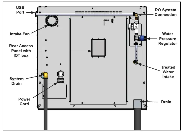
Water Supply Plumbing
The Steam and Hold is equipped witha standard 1/4 NPT female water connection. Also included with the steamer is a quick disconnect fitting (p/n’s 2080134 (Male) & 2080118 (Female)) which can be readily adapted and/or permanently secured to a flexible water feed line that delivers water pressure at a minimum of 40 psig and a maximum of 60 psig. CA minimum flow rate of 1 gpm is required.
NOTE:
Minimum dynamic supply water pressure (from a softener, RO system, or tap water supply line) to be 40 psig minimum and a maximum of 60 psig. Contact Antunes Tech Service on measuring the proper supply water pressure.
| Antunes Recommended Clearances from walls and other Equipment | |||
| Front of Steamer | Rear of Steamer | Left Side of Steamer | Right Side of Steamer |
| 36” – 48” for full drawer extension | 6”- 8” for proper air flow | 6” for ease of cleaning and maintenance | 6” for ease of cleaning and maintenance |
| Agency Required Clearances from walls and other Equipment | |||
| 36” | 6” | 0” | 0” |
Supply Wiring
WARNING
ELECTRICAL SHOCK HAZARD Disconnect power before servicing. Replace all parts and panels before operating. Failure to do so can result in electrical shock or death.
WARNING
An electrical ground is required to the wall receptacle. Failure to provide a proper ground can result in death or serious injury. All applicable electrical codes MUST be followed in accordance with ANSI/NFPA 70 or latest edition. In Canada, provide electrical service in accordance with Canadian electrical code, CSA C22.1 and local codes.
- Remove the four side panel screws as shown below.

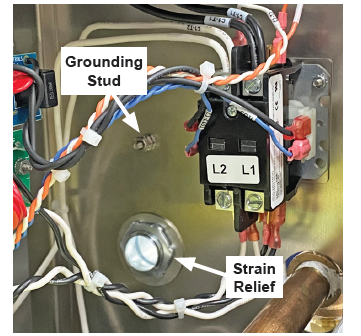
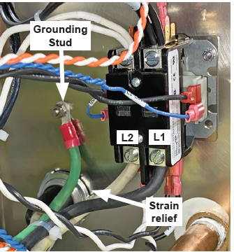
- Route power supply (not included) through the strain relief as shown below and secure with screw.

- Connect black and white wires to contactor as shown. Connect Line Voltage Input to Contactor L1 and L2. Use torque screw driver set at 35in-lb.

- Connect green ground wire to grounding stud using provided nut. Use torque nut driver set at 20 in-lbs.
- Reassemble side electrical panel.
System Water Drainage
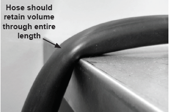
A 9 ft. roll of high temperature 3.4” I.D. flexible hose is provided and connections must be made in the field. Kinking of the hose, will impede the performance and functionality of the Steam and Hold.
- Measure distance from steamer drain to floor drain making sure to leave room for a two (2) inch gap between the hoses and floor drain.
- Cut the supplied drain tubing for drain connection.

Operations
Initial Startup
- Connect the water treatment system to the treated water inlet according to Figure 3 on page 6.
- Plug the power cord into the appropriate outlet. Turn on water.
- The steamer performs a system test and displays information on the display.
- The steamer then shows the splash screen. Press the Power Button to turn the steamer on.
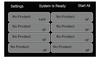
- The steamer displays the main screen and fills the internal tank.
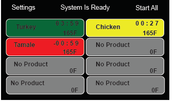
- When the tank is filled and the unit reaches temperature, the steamer displays “System is Ready” on the main screen.
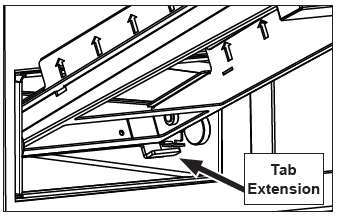
Inside of the drawer cavity is a roller and a rail cutout on either side. The cutout is located right behind the roller. On the bottom rear edge of each drawer is a tab extension. The tab helps to keep the drawer inside the cavity. See Figure 5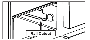
To Install:
- Hold the drawer at about a 30 degree angle. Insert the drawer tabs through the cutouts in the drawer rails so the tabs are under the rails.

- Rotate the drawer down and insert pan.
- Drawer should now easily close and seal.
System Power-up
- Upon application of power, the system will display the following splash screen.

- After initializing the system will display:

- NOTE: The system will display Wakeup Disabled when the automatic Wakeup function is not enabled. When the Wakeup function is enabled, the screen will display ‘Wakeup X:XX’ where X is the set time.
- Press and Hold the Power Button on the Control Panel to begin. The unit will display “System is Not Ready”, begin to fill with water, and start the heating process. Once the unit reaches temperature the screen will display:


Programmed Steaming
- When the Initial Warm-up is complete, the operations screen appears on the display.
- Open the appropriate drawer and load the product to be steamed onto the steam trivet. Close the drawer securely.
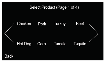
- On the display, press the appropriate button for the drawer being used.
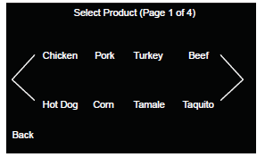
- Select the product from the pre-loaded options.

- After selecting the product, select the product size to steam.

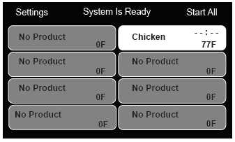
- There are two options for steaming: Now or Later. If Now is selected the unit will return to the main screen and begin steaming.

- If Start Later is selected the unit will return to the main screen. The newly created timer will wait for further instruction before starting. This is indicated by the –:–.

- Tap the button for the primed timer. There are three options: Start the timer, Delete the timer (trash), or change the steaming options for the drawer.

- Drawers display three different colors and timers:
- Yellow – The drawer is STEAMING
- Green – The drawer is HOLDING
- Red – The drawer is EXPIRED

- Once a drawer has finished steaming, the drawer will switch to holding. Product may be removed and used during any time while the drawer is holding.


First In First Out (FIFO)
The Steamer uses a feature called First In First Out. FIFO helps make sure product placed into the unit first is the first product removed. If there is more than one drawer running the same product and size, the display and beeper will prompt the user to pull product from the drawer that was started earliest.
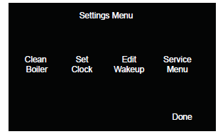
Steamer Settings
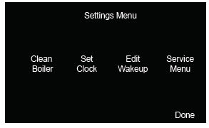
To access the Steamer Settings, press the Settings button on the display. This opens the Settings screen, shown below.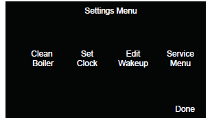
The Settings Screen shows three buttons, described below:
| Button | Description |
|
Edit Product | Select to access the Edit Screen for access to editing products, steaming times, and product names. |
| Edit Clock | Changes the date and time. |
| Edit Wakeup | Changes the time in which the Steamer turns on. |
|
Clean Boiler | This option works with the Antunes RO system. Please see your RO manual for information on how to use the clean cycle. |
| Service | Displays information necessary for servicing/ repairing the unit. |
Editing Products
To Edit Products:
- Press Settings to open the settings menu.
- Press Edit Products.
- Select the product you wish to edit from the available list (see below).

- The following screen displays:
- Select any field to edit. Anything that is changed will save automatically or press Cancel to discard any changes.


Edit Clock
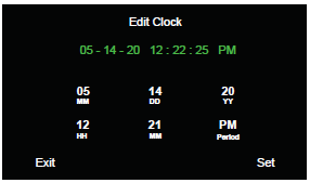
To change the time and date on the Steamer:
- Select Edit Clock in the Tools Screen.
- The screen will display as shown below:

- Tap each designated field to set the time and date. Press Set to save changes. The clock will begin ticking.


Edit Wakeup
To change the time when the Steamer turns on and Disable or Enable Wakeup Mode:
- Select Edit Wakeup in the Tools Screen.
- The screen will display as shown:

- Select each field to change the time, AM or PM, and Disable or Enable Wakeup Mode.

- Press OK to save.


Service Menu
To enter Service menu:
- Press Settings to open the settings menu.
- Press Service.

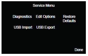
Diagnostics
Diagnostics displays the items that the unit is constantly measuring. This cannot be edited.
Edit Options
Edit Options allows ability to adjust various system settings and set a Password.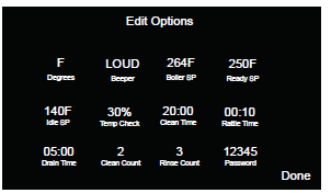
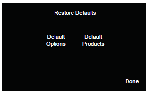
Restore Defaults
Allows system to reset to default Options, and Products to factory settings.
NOTE:
Do NOT adjust set points or clean cycle times unless instructed to by Antunes Technical Service.
Reset to Factory Defaults
IMPORTANT:
Resetting the Steam and Hold to Factor Defaults erases all edits, menu changes, and customized functions back to Factory Settings.To reset settings to the factory defaults:
- Press Settings on the display. This opens the Settings screen, shown below:

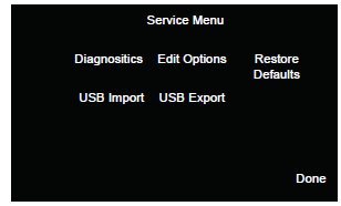
- Select Service to open the Service Menu. Press Restore Defaults.

- Restore Defaults option opens. Default Options and Default Products is shown.

- Press either of the functions to restore to the factory defaults.

- Press Done to return to the Service Menu.

Maintenance
Daily
The Steam and Hold requires a minimal amount of maintenance. Daily maintenance helps keep the steamer running smoothly and free of any excess buildup that comes from daily use and wear. These steps should be completed at the end of every day to ensure that the steamer maintains optimum efficiency. Open the drawers and remove the steam pans and steam trivets (Figure 8).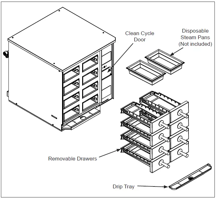
- Remove the drip trays
- Wash, rinse, and sanitize the drip trays at the sink. Allow to air dry.
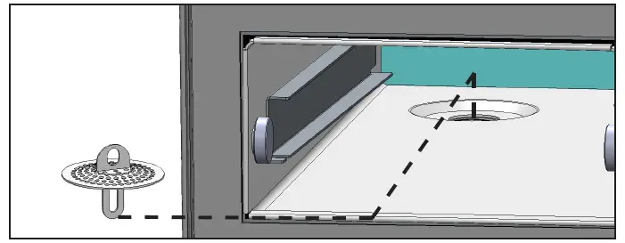
- Remove all cavity drain screens and rinse clean of any debris
- Clean the steam drawers and the inner cavity with a clean towel dampened with sanitizer. Allow to air dry.
- Reinstall all parts

Weekly
Clean Cycle Maintenance
The cleaning cycle can be accessed and performed at any time during the day. When low mineral content (low TDS) water is used with the steamer, the clean cycle should only be needed monthly. Higher mineral content water may require more frequent clean cycles.
NOTE:
Failure to properly clean and de-scale boiler will cause significant changes in operation of steamer. Antunes is not responsible for any damage or complications due to negligent maintenance of steamer.
- Select Settings. The Settings Menu screen opens.

- Select Clean Boiler to begin the Clean Cycle.

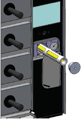
- Remove the Cycle Key and insert it into the Cleaning Cartridge (Figure 9).
 Rotate cartridge counter-clockwise and remove from steamer.
 - Remove top of Cleaning Cartridge by pulling top off the plastic housing.
- Pour 4oz of cleaning solution into the plastic housing (Figure 10).

- Reattach top of Cleaning Cartridge.
- Place Cleaning Cartridge back into steamer.
- Rotate the supplied key clockwise to tighten cartridge. Steamer is now ready to perform Clean Cycle.
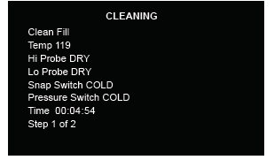
- Press OK to begin the cleaning cycle. The following screen appears and begins the cleaning cycle.

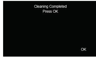
- When the Cleaning Cycle is complete, the following screen appears. Press OK to return to the Tools Menu.


 Rotate cartridge counter-clockwise and remove from steamer.
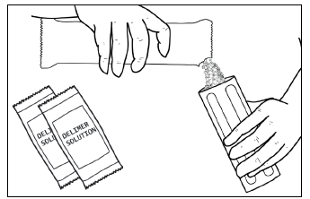
Rotate the door down and remove key from pocket. Insert key into clean cycle cartridge, counter clockwise, and remove from steamer. Remove top of cartridge by pulling it off the plastic housing.
Weekly Maintenance – Cleaning Cycle
WARNING
Failure to properly follow the cleaning instructions for the unit will result in excess buildup of scale and lime as seen in the examples below. Excess buildup of scale and lime may cause damage to the unit and will void the warranty.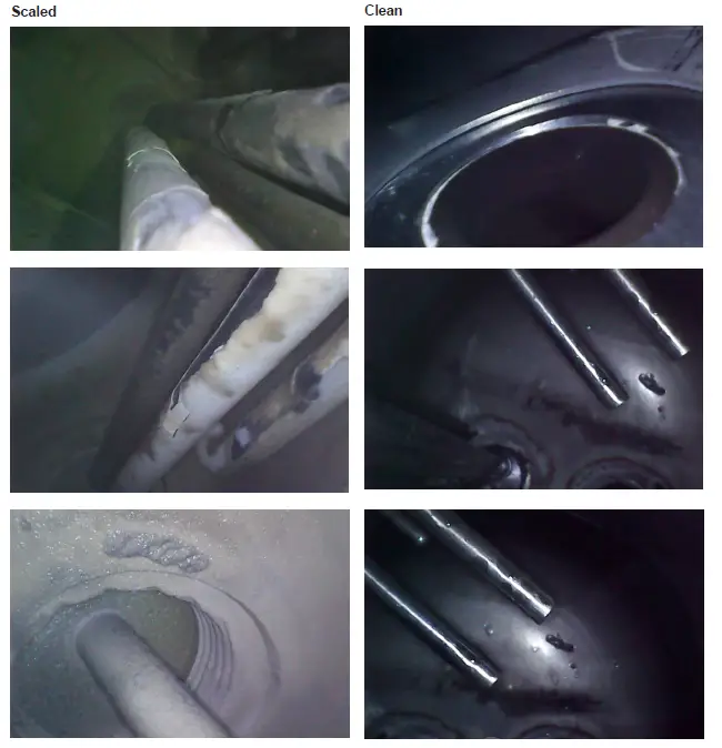
Error Messages
If the steamer displays any error messages, turn the steamer off and restart it. If the error persists, contact Antunes Technical Service at 1-877-392-7854 (toll free).
WARNING
Before replacing any parts, or opening any side or rear panel from the steamer, disconnect the steamers from the electrical power supply.
CAUTION
Use of any replacement part other than those supplied by Antunes of their authorized distributors can cause injury to the operator and damage to the equipment and will void all warranties.
| Error | Description |
| FRAM Missing | Control Board Failure |
| Zero Cross | |
| TC0 Open | Thermocouple Broken or Disconnected |
| TC1 Open | |
| FlipFlop ON | Power Switch Circuit Malfunction |
| FlipFlop OFF | |
| Bootload Fail | Software Update via USB Stick Failed |
| OPTION Write Failed | EEPROM Failure |
| MENU Write Failed | |
| PID Write Failer | |
| 24V Missing | 24VDC Power Supply Failed |
| Display Missing | Touch Screen Display Failed |
| Boiler Hot | Boiler Failed to Cool Down |
| Boiler Not Empty | Boiler Failed to Drain |
| Drain Timeout | |
| Clean Drain Timeout | Boiler Failed to Cool Down |
| Initial Fill Timeout | Boiler Initial Water Fill Failed |
| Clean Fill Timeout | Boiler Clean Cycle Water Fill Failed |
| Refill Timeout | Boiler Normal Operation Water Fill Failed |
Troubleshooting
Your Antunes Steamer is designed to operate smoothly and efficiently if properly maintained. However, the following is a list of checks or activities to make in the event of a problem:
| Problem | Possible Cause | Who Services Steamer | Corrective Action |
| Excessive steam escaping from the cavity | Cavity Drain Screen is Plugged | User | Remove both drawers of steamer and clean Drain Screens. |
| Drain Hose is kinked or 2″ air gap is blocked | User | Make sure the drain hose are not kinked and a 2” air gap is maintained to the floor drain or drain box. | |
|
Excessive water is pouring out of the cavity | Water Probes Scaled | User | Run one or more clean cycles. Check the water treatment system. |
| Cavity Drain Screen is Plugged | User | Remove both drawers of steamer and clean Drain Screens. | |
| Drain Hose is kinked or 2″ air gap is blocked | User | Make sure the drain hose are not kinked and a 2” air gap is maintained to the floor drain or drain box. | |
| Water fill Solenoids are clogged | Auth Service Rep Only | Check water fill solenoids for debris. | |
| Steam Solenoid Valves are clogged. | Auth Service Rep Only | Check Steam Solenoids Valves for debris and continuity (N.C.) for normal operation. | |
|
Steamer Does Not Heat | Steamer is unplugged or circuit breaker is tripped | User | Make sure steamer is plugged in and circuit breaker has not tripped. |
| Cavity Drawer(s) are not fully inserted. | User | Make sure both cavity drawers are pushed in all the way. | |
| Loose component connections | Auth Service Rep Only | Check operation of Pressure Switch, Control Board, Contactor, and Cartridge Heaters for continuity and/or loose connections. | |
| Steamer fails to reach proper temperature | GUI Settings have changed | User | Adjust GUI Control Settings and set Boiler Temperature (BT) to 268 deg 0F. See settings/ operation section in this manual on page 17. |
| Voltage issue on electrical components | Auth Service Rep Only | Check for voltage or open circuit on control board, contactor, heaters, pressure switch, or GUI control Panel. | |
| Steamer is continually draining and doesn’t build pressure or temperature | System buildup or blockage. | User | Turn steamer off and run a clean cycle. Allow steamer to complete the entire clean cycle – See preventative maintenance section of this manual on page 18. |
| Drain Valve malfunction/failure. | Auth Service Rep Only | Clean the drain valve seat or replace drain valve with the steamer powered down. Once powered up, run a clean cycle to ensure trouble free operation. | |
| Steam is escaping from the rear panel of the steamer | Internal Component Failure | Auth Service Rep Only | Shut down and unplug the unit. Call Authorized Service Rep. |
| Water is escaping from rear of steamer during initial operation | Water Inlet Hose has connection problem | User | Check inlet water feed hose to steamer. Reconnect if needed and/or replace. |
| Water level probe scaled up | User | Run a cleaning cycle. | |
| System Error Displayed on GUI | System Error – Refer to Error Messages on Next Page | User | Turn steamer OFF and then back ON. If error persists, contact Authorized Service Rep |
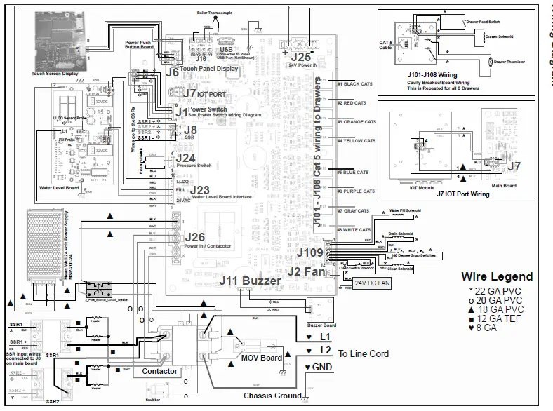
Wiring Diagram
Exploded Diagram #1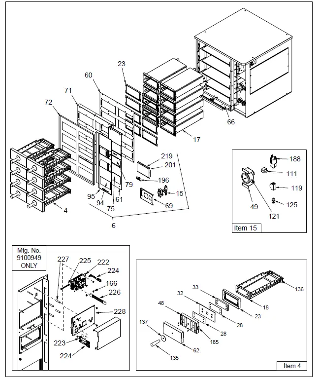
Exploded Diagram #2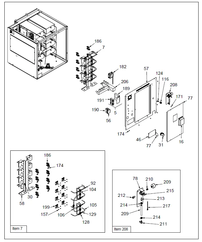
Exploded Diagram #3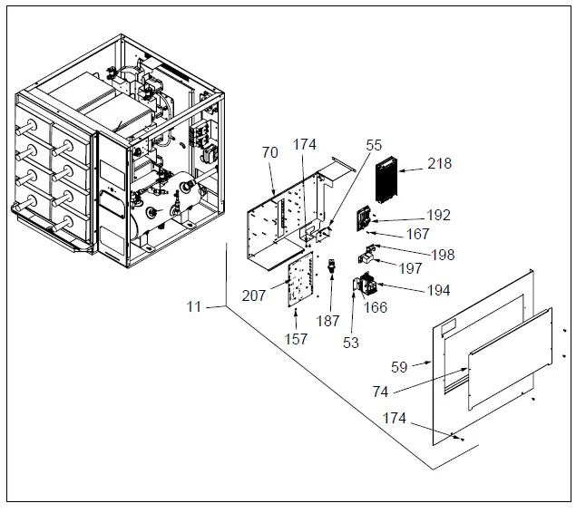
Exploded Diagram #4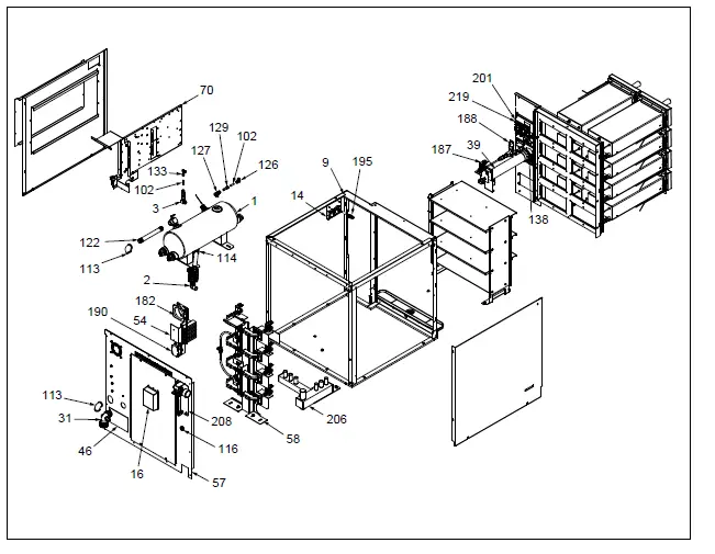
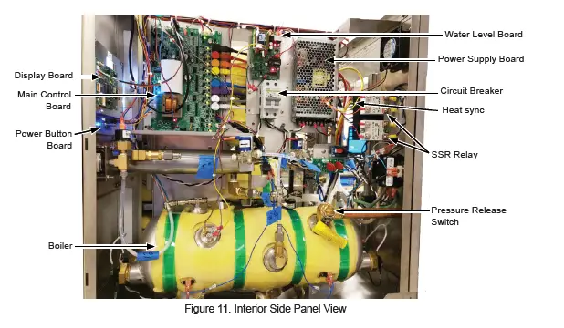
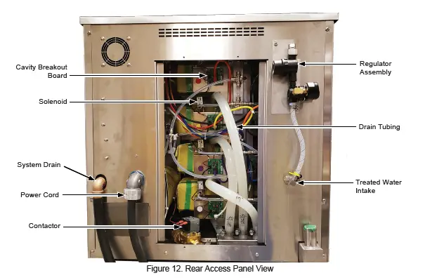
Photo Diagram

Replacement Parts
Parts List
(See Exploded Views for more information)
NOTICE
Use only genuine Antunes replacement parts in this unit. Use of parts other than those supplied by the manufacturer will void the warranty.
| Item No. | Part # | Description | Qty. |
| 1 | 0014106 | Boiler Assembly | 1 |
| 2 | 0014153 | Drain Pipe Assembly | 1 |
| 3 | 0014154 | Fill Valve Piping Assy | 1 |
| 4 | 0014162 | Tray Assy | 8 |
| 5 | 0014196 | SSR Assy | 1 |
| 6 | 0014243 | Control Panel Assy | 1 |
| 7 | 0014434 | Control Tower Assy | 1 |
| 8 | 0014435 | Sensor Brkt Mt Assy | 8 |
| 9 | 0014439 | Frame Weldment | 1 |
| 10 | 0014441 | Front Access Cover Assy | 1 |
| 11 | 0014443 | Ele Panel Assy | 1 |
| 12 | 0014481 | Clean Cycle Module Complete Assy | 1 |
| 13 | 0014497 | Back Panel Assy | 1 |
| 14 | 0014503 | Buzzer Assy | 1 |
| 15 | 0014580 | Pressure Switch Assy | 1 |
| 16 | 0014601 | Iot Box Assy | 1 |
| 17 | 0014147 | Cavity Assy | 8 |
| 18 | 0024463 | Large Tray Frame Weldment | 8 |
| 23 | 0209302 | Drawer Gasket 8D | 8 |
| 30 | 0400119 | Bushing, Shorty 5/8 | 2 |
| 31 | 0400649 | Connector, 3/4 Conduit | 1 |
| 34 | 0508228 | Bracket, Clean Cycle Support | 1 |
| 35 | 0508229 | Actuator, Clean Cycle Plunger | 1 |
| 36 | 0508230 | Bushing, Clean Cycle Bracket | 1 |
| 37 | 0508231 | Frame, Clean Cycle Front | 1 |
| 38 | 0508232 | Cap, Clean Cycle Threaded Outer | 1 |
| 39 | 0508233 | Housing, Tube Clean Cycle | 1 |
| 40 | 0508236 | Tube, Internal Clean Cycle Delimer Cartridge | 1 |
| 41 | 0508237 | Adapter, Clean Cycle Internal Cartridge Cap | 1 |
| 42 | 0508238 | Screen, Deliming Cartridge | 1 |
| 43 | 0508239 | Adapter, Closed End Clean Cycle Cartridge | 1 |
| 44 | 0509885 | Support Angle | 6 |
| 45 | 0509888 | Cubby Bottom Lg | 8 |
| 46 | 0509912 | Cover, Heating Element 3 Pan Gen. Market | 1 |
| 48 | 0510101 | Front Plate | 8 |
| 49 | 0510386 | Braket Gauge | 1 |
| 53 | 0510849 | Circuit Breaker Bracket | 1 |
| 54 | 0510883 | SSR Mt Bracket | 1 |
| 55 | 0510884 | Snub And Varistor Mt Plate | 1 |
| 56 | 0510885 | Contactor Mt Plt | 1 |
| 57 | 0510967 | Back Panel Full | 1 |
| 58 | 0510970 | Valve Stand | 1 |
| Item No. | Part # | Description | Qty. |
| 59 | 0510972 | Side Pane Rh | 1 |
| 60 | 0510973 | Cubby Front Brace | 1 |
| 61 | 0510978 | Control Panel | 1 |
| 62 | 0510979 | Front Plate | 8 |
| 66 | 7002357 | Drip Pan Kit | 1 |
| 69 | 0511265 | Clean Cycle Mt Brkt | 1 |
| 70 | 0511272 | Electrical Mount Bracket | 1 |
| 71 | 0511278 | Front Cover Panel | 1 |
| 72 | 0511284 | Front Cover Panel Os | 1 |
| 74 | 0511289 | Side Ele Panel | 1 |
| 75 | 0511290 | Front Access Cover | 1 |
| 76 | 0511357 | Bracket, Clean Cycle Support | 2 |
| 77 | 0511360 | Back Access Door | 1 |
| 78 | 0511361 | Bracket, Mounting | 1 |
| 79 | 0511387 | Clean Cycle Door | 1 |
| 80 | 0511407 | Buzzer Bracket | 1 |
| 85 | 0511634 | Rail Lh | 8 |
| 86 | 0511635 | Rail Rh | 8 |
| 87 | 0511639 | Tray Frame 8D | 8 |
| 88 | 0511640 | Stop Bracket | 8 |
| 92 | 0511666 | Top Fitting Support | 1 |
| 94 | 1002835 | Front Access Label | 1 |
| 95 | 1002838 | Label, Control Panel 8D | 1 |
| 102 | 2000595 | Tube, 1/4Od X 1Lg | 2 |
| 104 | 2000599 | Tube, 5/16Od X 2Lg Steam | 4 |
| 105 | 2000607 | Tube, Elbow | 8 |
| 106 | 2000609 | Tubing, .312 Elbow | 2 |
| 108 | 2000613 | Tubing 1/4Od X 4″Lg | 1 |
| 111 | 2060125 | Elbow90 Deg, 1/8 Npt X 1/8 Nptf | 1 |
| 112 | 2060136 | Valve, Check 1/4 Nptm | 3 |
| 113 | 2060141 | Elbow, 90 Deg 1/2 Npt Brass | 1 |
| 114 | 2060143 | Tee, 1/2 Npt F X M X F Brass | 1 |
| 115 | 2060144 | Plug, Pipe 1/2 Npt Brass Mcmaster 50785K115″ | 1 |
| 116 | 2060151 | Coupling, Bulkhead Panel Mount 1/4 Nptf | 1 |
| 117 | 2060158 | Elbow, 90 Degree Brass 1/4 Npt | 2 |
| 118 | 2060168 | Union, Straight Brass 1/2 Npt | 1 |
| 119 | 2060172 | Tee, 1/8 Npt Machined Brass | 1 |
| 121 | 2060179 | Gauge, Pressure 1/8 Nptm Panel Mount | 1 |
| 122 | 2060206 | Pipe Nipple 7″ 1/2Npt Brass | 2 |
| 123 | 2070142 | 1/4 Tube X 1/4Npt Female | 1 |
| 124 | 2070143 | Elbow,1./4Npt X 1/4Hose Sst | 1 |
| 125 | 2070147 | 1/4 Tube X 1/8Npt Straight Sst | 1 |
| 126 | 2070148 | Elbow, 1/4Tube X 1/4 Tube | 1 |
| 127 | 2070175 | Tee, 5/16 Tube X 1/4Nptm | 1 |
| 128 | 2070177 | Tee, 5/16 Tube Sst | 7 |
| 129 | 2070178 | Reducer, 5/16 Tube X 1/4 Tube Ss | 9 |
| 130 | 2070179 | Fitting, 1/4Tube X 1/8Nptf Ssta | 2 |
| 131 | 2070181 | Barb Fitting 1/2Npt X .75 Hose | 8 |
| 132 | 2070183 | Fitting 45° 3/4Hose X 1/2Npt | 1 |
| 133 | 2080149 | Fitting, Tee Push To Connect | 2 |
| 135 | 2100107 | Handle, 3/8-16 Insert | 8 |
| 136 | 2100195 | Bearing .90 Dia X .25Thk | 32 |
| 137 | 2100432 | Heat Shield Disk | 8 |
Replacement Parts Continued
| Item No. | Part # | Description | Qty. | Item No. | Part # | Description | Qty. | ||
| 138 | 2110223 | Key | 1 | 189 | 4050180 | Heat Sink | 2 | ||
| 139 | 2120174 | Spacer, #10, 5/15 Od X 3/16 Lg | 1 | 190 | 4050236 | Contactor, 2 Pole Normally Open | 1 | ||
| 140 | 2120249 | Spacer, .115 Id X .25 Od .062 , Nylon | 8 | 191 | 4051010 | Relay, Random Phase, Solid State | 2 | ||
| 192 | 4051059 | Board Water Level | 1 | ||||||
| 141 | 2120273 | Standoff, Pem – Bsos-632-16 | 5 | ||||||
| 193 | 4058132 | Probe, Thermistor | 8 | ||||||
| 142 | 2120302 | Round Spacer, .115 Id X .192 Od X 3/4″H | 4 | ||||||
| 194 | 4058191 | Circuit Breaker | 1 | ||||||
| 195 | 4060487 | Usb | 1 | ||||||
| 143 | 2120378 | Spacer, #4 X.18Od X.13Lg Ss | 1 | ||||||
| 196 | 4070088 | PCB, Power Switch W/Leds | 1 | ||||||
| 144 | 2120379 | Spacer, #4X,5Lg .18Od Ss | 4 | ||||||
| 197 | 4070221 | Varistor Board | 1 | ||||||
| 145 | 2160219 | Fitting, Pipe 1/4 Npt Clean Cycle Feed -Welded | 1 | ||||||
| 198 | 4070198 | Snubber Board | 1 | ||||||
| 199 | 4070387 | PCB, Valve | 8 | ||||||
| 146 | 2160220 | Fitting, Pipe 1/4 Npt Drain Welded | 1 | ||||||
| 200 | 4070422 | PCB Buzzer | 1 | ||||||
| 152 | 2190178 | Nipple Pipe, 1/8″ Npt | 1 | ||||||
| 201 | 4070430 | PCB, Capacitive Display | 1 | ||||||
| 153 | 3010112 | Screw, Weld 3/8-16 S/S | 8 | ||||||
| 204 | 2070165 | Elbow 1/2 Npt Sst | 8 | ||||||
| 154 | 3020109 | Rivet, 1/8 Blind | 1 | ||||||
| 206 | 0024386 | Drain Box 3 Pan Steamer | 1 | ||||||
| 155 | 3020136 | #2-56 Ss Hex Nut | 2 | ||||||
| 207 | 4070426 | Main PCB | 1 | ||||||
| 156 | 3020137 | Screw, #2-56 X 7/8″ Lg 18-8 S.S. Pan Hd Phillips | 2 | ||||||
| 208 | 7002130 | Regulator Assy | 1 | ||||||
| 157 | 3040105 | Nut, Hex ‘Keps’ #4-40 Zinc | 55 | 209 | 2030144 | Tubing -C, 1/4″ I.D. Pvc Brd | 1 | ||
| 158 | 3040114 | Scr, Mach. #4-40 X 1/4″ | 4 | 210 | 2060159 | Bushing, Hex Brass1/4 Nptm X 1/8 Nptf | 1 | ||
| 159 | 3040123 | 4-40 X .38 Lg Pan Hd Phillips | 6 | ||||||
| 211 | 2080105 | Elbow, Qik Disc (Sov) – 1/4″ | 1 | ||||||
| 160 | 3040132 | 4-40 Flat Head Soc. Head X .312 Lg | 16 | ||||||
| 212 | 2080118 | Quick Disconnect-1/4″ Npt | 1 | ||||||
| 161 | 3040141 | Screw Flat Hd #4-40 X 1/4 18-8 S.S. 82 Deg Undercut | 4 | 213 | 2080134 | Quick Disconnect-Male 1/4″ Npt Brass | 1 | ||
| 162 | 3040155 | 4-40 X 1 1/8″” Pan Hd, Phillips Screw | 4 | 214 | 2110104 | Clamp, Worm-Drive (S/S) | 2 | ||
| 215 | 2170208 | Regulator, Water Pressure | 1 | ||||||
| 163 | 3040163 | Nut, 4-40 Keps | 4 | 216 | 2170209 | Pressure Gauge | 1 | ||
| 164 | 3040173 | Screw, 4-40 X 1/4Lg Sst | 16 | 217 | 4060118 | Wire, Tie | 1 | ||
| 165 | 3040175 | Nut, 4-40 Keps 18-8 Sst | 32 | 218 | 4060578 | Power Supply | 1 | ||
| 166 | 3060130 | Nut,Hex””Keps”” #06-32 Steel; Zinc Plated | 10 | 219 | 4070463 | PCB, Resistive Display | 1 | ||
| 220 | 7002428 | Large Tray Assembly Kit, 8 Drawers | 1 | ||||||
| 167 | 3060136 | Screw, Mach #6-32 X 3/8″ | 5 | ||||||
| 168 | 3080104 | 8-32 X 3/8 Lg S.S. Truss Head | 1 | 221 | 7002429 | Large Tray Assembly Kit, Single Drawer | 1 | ||
| 169 | 3080124 | 8-32 X .5 Lg Round Hd. One-Way | 1 | ||||||
| 170 | 3080143 | Nut, Hex ‘Keps’ #8-32 | 13 | 222 | 4070469 | ASY-PCB, Raspberry Pi Display Adapter Assembly (Mfg. No. 9100949 Only) | 1 | ||
| 171 | 3080145 | Nut, Hex Acorn #08-32 Low Crown | 6 | ||||||
| 172 | 3080186 | Washer, #8 Split Lock | 16 | ||||||
| 223 | 0701143 | Cable Assy, HDMI (Mfg. No. 9100949 Only) | 1 | ||||||
| 173 | 3080199 | Nut, Hex Keps #8-32 S/S | 18 | ||||||
| 174 | 3080203 | Screw #8-32 X 3/8 With Int. Tooth Washer | 88 | ||||||
| 224 | 0701144 | Cable Assy, Micro USB (Mfg. No. 9100949 Only) | 2 | ||||||
| 175 | 3080401 | Standoff, #8-32 X 7/8Lg .28Od Sst | 32 | ||||||
| 176 | 3080402 | Screw, #8-32 X .38L Fh W/Ring | 60 | 225 | 0701142 | Power Cable, Display Board (Mfg. No. 9100949 Only) | 1 | ||
| 177 | 3100123 | Screw,Mach #10-24 X 1/2″ | 1 | ||||||
| 178 | 3100157 | Washer, Flat #10 | 17 | 226 | 0701153 | Connector Cable (Mfg. No. 9100949 Only) | 1 | ||
| 179 | 3100178 | Screw, Hex Bolt #10-32 X 3/8″ | 4 | ||||||
| 227 | 3060226 | Standoff, 1/4” OD X 1 1/8” LG, Nylon (Mfg. No. 9100949 Only) | 4 | ||||||
| 180 | 3100308 | Weld Nut, #10-32 | 8 | ||||||
| 181 | 3250302 | 1/4-20 Pem Nut Sst | 32 | ||||||
| 228 | MOD02- 0020 | MOD, LCD, 7” Cap Touch HDMI, USB, Noritake (Mfg. No. 9100949 Only) | 1 | ||||||
| 182 | 4000216 | Fan | 1 | ||||||
| 183 | 4010254 | Micro-Switch | 2 | ||||||
| 184 | 4010260 | Switch, Reed | 8 | ||||||
| 185 | 4010261 | Actuator, Reed Switch | 16 | ||||||
| 186 | 4040207 | Solenoid Valve .060 High Temp | 8 | ||||||
| 187 | 4040239 | Solenoid Valve .088 Orifice | 2 | ||||||
| 188 | 4040266 | Low Pressure Switch, Fixed 28 Psi | 1 | ||||||
Limited Warranty
Equipment manufactured by Antunes has been constructed of the finest materials available and manufactured to high quality standards. These units are warranted to be free from electrical and mechanical defects for a period of one (1) year from date of purchase under normal use and service, and when installed in accordance with manufacturer’s recommendations. To insure continued operation of the units, follow the maintenance procedures outlined in the Owner’s Manual. During the first 12 months, electromechanical parts, non-overtime labor, and travel expenses up to 2 hours (100 miles/160 km), round trip from the nearest Authorized Service Center are covered.
- This warranty does not cover cost of installation, defects caused by improper storage or handling prior to placing of the Equipment. This warranty does not cover overtime charges or work done by unauthorized service agencies or personnel. This warranty does not cover normal maintenance, calibration, or regular adjustments as specified in operating and maintenance instructions of this manual, and/or labor involved in moving adjacent objects to gain access to the equipment. This warranty does not cover consumable/wear items. This warranty does not cover damage to the Load Cell or Load Cell Assembly due to abuse, misuse, dropping of unit/shock loads or exceeding maximum weight capacity (4 lbs). This warranty does not cover water contamination problems such as foreign material in water lines or inside solenoid valves. It does not cover water pressure problems or failures resulting from improper/incorrect voltage supply. This warranty does not cover Travel Time & Mileage in excess of 2 hours (100 miles/160 km) round trip from the nearest authorized service agency.
- Antunes reserves the right to make changes in design or add any improvements on any product. The right is always reserved to modify equipment because of factors beyond our control and government regulations. Changes to update equipment do not constitute a warranty charge.
- If shipment is damaged in transit, the purchaser should make a claim directly upon the carrier. Careful inspection should be made of the shipment as soon as it arrives and visible damage should be noted upon the carrier’s receipt. Damage should be reported to the carrier. This damage is not covered under this warranty.
- Warranty charges do not include freight or foreign, excise, municipal or other sales or use taxes. All such freight and taxes are the responsibility of the purchaser.
- THIS WARRANTY IS EXCLUSIVE AND IS IN LIEU OF ALL OTHER WARRANTIES, EXPRESSEOR IMPLIED, INCLUDING ANY IMPLIED WARRANTY OR MERCHANTABILITY OR FITNESS FOR A PARTICULAR PURPOSE, EACH OF WHICH IS HEREBY EXPRESSLY DISCLAIMED. THE REMEDIES DESCRIBED ABOVE ARE EXCLUSIVE AND IN NO EVENT SHALL ANTUNES BE LIABLE FOR SPECIAL CONSEQUENTIAL OR INCIDENTAL DAMAGES FOR THE BREACH OR DELAY IN PERFORMANCE OF THIS WARRANTY.
The warranty does not extend to:
- Damages caused in shipment
- Installation of electrical service
- Installation, calibration, or adjustment
- Normal maintenance outlined in this manual
- Consumable parts such as egg rings, gaskets, rubber feet, labels, O-rings, light bulbs, etc.
- Malfunction resulting from improper service or maintenance
- Damage caused by improper installation, improper use, abuse, or careless handling
- Damage from moisture coming in contact with electrical components
- Damage from tampering with, removal of, or changing preset controls or safety devices
- Damage caused by parts or components not provided by Antunes
- Failure to meet water quality requirements


