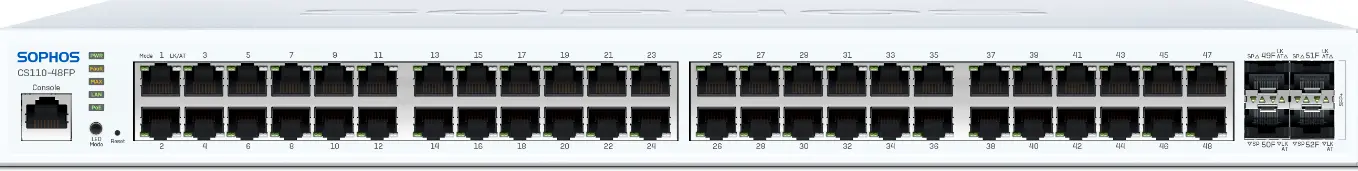
SOPHOS CS110-48FP Rackmount Gigabit Managed Switch
Note: All ports on a PoE model are PoE capable according to 802.3af/at standard, CS210-8FP also supports the 802.3bt standard
Product Information: Sophos Switch Series
The Sophos Switch Series is a network switch designed for businesses looking to manage their network traffic efficiently. The switch is available in different models, each with varying port configurations and power capabilities. The switch can be managed through the Sophos Central management platform, and users must have a valid license to manage the switch.
Included in the Box
- Sophos Switch
- Power Adapter (CS101-8FP model only)
- Power Adapter (region-specific) (CS101-8 model only)
- Power cable (region-specific) (except CS101-8/8FP)
- RJ45 to DB9 Console cable (except CS101-8/8FP)
- Quick Start Guide and Safety Instructions
- Rackmount Kit (except CS101-8/8FP)
- Rubber feet
Interfaces
The switch has different interfaces depending on the model.
These include:
| Model | 1G LAN Ports | 2.5G LAN ports | SFP/SFP+ Fiber ports | Max. PoE Capacity |
|---|---|---|---|---|
| CS101-8 | 8 | 0 | 2 SFP | N/A |
| CS101-8FP | 8 | 0 | 2 SFP | 110W |
| CS110-24 | 24 | 0 | 4 SFP+ | N/A |
| CS110-24FP | 24 | 0 | 4 SFP+ | 410W |
| CS110-48 | 48 | 0 | 4 SFP+ | N/A |
| CS110-48P | 48 | 0 | 4 SFP+ | 410W |
| CS110-48FP | 48 | 0 | 4 SFP+ | 740W |
| CS210-8FP | 0 | 8 | 4 SFP+ | 240W (802.3af/at), 60W (802.3bt) |
| CS210-24FP | 16 | 8 | 4 SFP+ | 410W |
| CS210-48FP | 32 | 16 | 4 SFP+ | 740W |
| Model | 1G LAN Ports | 2.5G LAN ports | SFP/SFP+ Fiber ports | Max. PoE Capacity | Max. 15W/30W/60W PoE Devices |
| CS101-8 | 8 | 0 | 2 SFP | N/A | N/A |
| CS101-8FP | 8 | 0 | 2 SFP | 110W | 7/3/- |
| CS110-24 | 24 | 0 | 4 SFP+ | N/A | N/A |
| CS110-24FP | 24 | 0 | 4 SFP+ | 410W | 24/13/- |
| CS110-48 | 48 | 0 | 4 SFP+ | N/A | N/A |
| CS110-48P | 48 | 0 | 4 SFP+ | 410W | 26/13/- |
| CS110-48FP | 48 | 0 | 4 SFP+ | 740W | 48/24/- |
| CS210-8FP | 0 | 8 | 4 SFP+ | 240W | 8/8/4 |
| CS210-24FP | 16 | 8 | 4 SFP+ | 410W | 24/13/- |
| CS210-48FP | 32 | 16 | 4 SFP+ | 740W | 48/24/- |
Note: All ports on a PoE model are PoE capable according to 802.3af/at standard, CS210-8FP also supports the 802.3bt standard
| Other Interfaces | Type | Comment |
| COM | RJ45 | You can connect a serial console to the RJ45 COM port to access the Command Line Interface (CLI). The required connection settings are:
|
| Reset | Button | Press and hold the reset button for 7 seconds to reset the switch to the factory default settings. All configuration including the login password will be reset. |
Product Usage Instructions
- Before deploying the switch, make sure you have access to Sophos Central and a valid license to manage the switch.
- To mount the switch in a rack, use the supplied rackmount kit (where available). For instructions on how to mount your switch, see the Operating Instructions at www.sophos.com/get-started-switch.
- Connect the power supply (where available) and/or supplied power cable to the switch and turn it on (if unit has a power button). After a few seconds, the Power LED will start blinking and the switch will boot. This process should take just a few minutes. After the boot-up is complete, the Power LED will turn to solid green.
- The switch can be managed through Sophos Central. Refer to the user manual for more information on how to manage your switch.
- To reset the switch to factory default settings, press and hold the reset button for 7 seconds. All configuration, including the login password, will be reset.
For more information about your switch, scan the QR code or visit www.sophos.com/get-started-switch

Before Deploying
Congratulations on the purchase of your Sophos Switch. This Quick Start Guide describes in short steps how to connect your switch and do the initial configuration. Before you begin, please make sure you have access to Sophos Central which is needed to manage your switch. Please ensure you have a valid license to manage the switch.
What is included in the box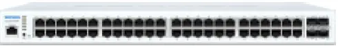
- Sophos Switch
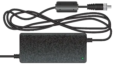
- Power Adapter CS101-8FP model only
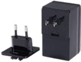
- Power Adapter
(region-specific) CS101-8 model only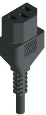
- Power cable
(region-specific) (except CS101-8/8FP)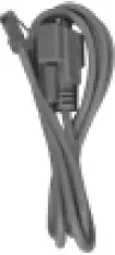
- RJ45 to DB9 Console cable
(except CS101-8/8FP)
- This Quick Start Guide and Safety Instructions
- Rackmount Kit
(except CS101-8/8FP)
- Rubber feet
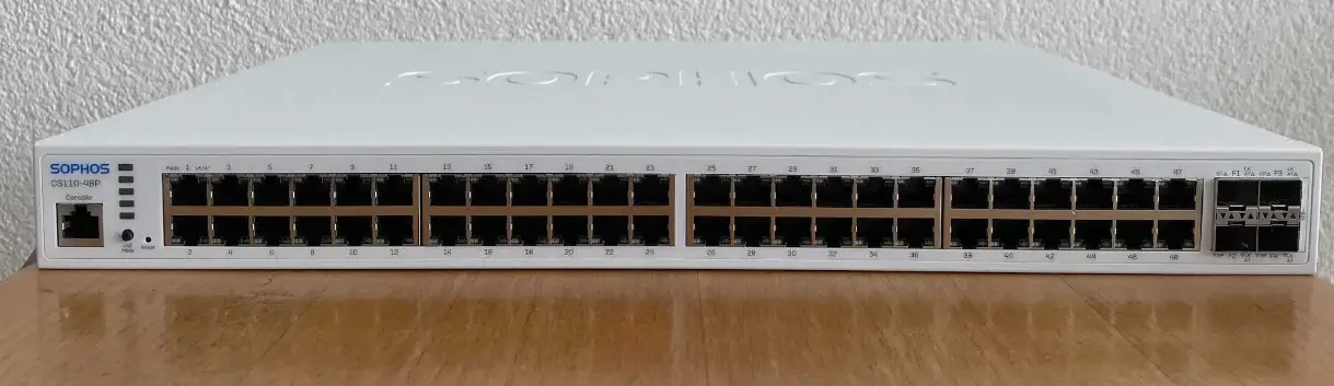
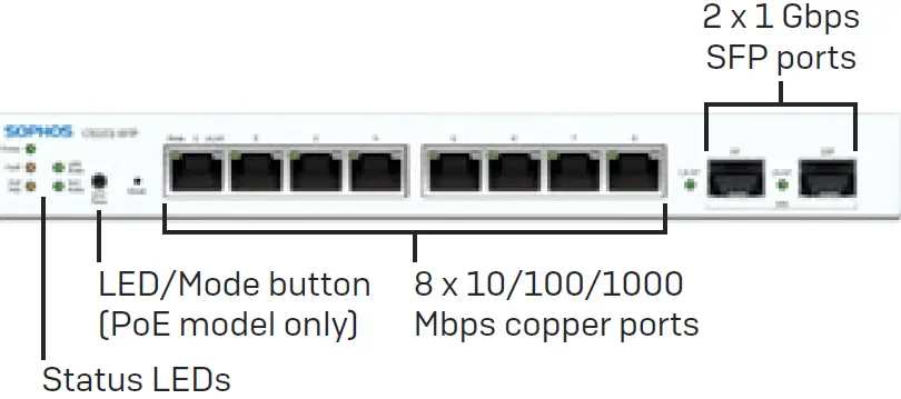
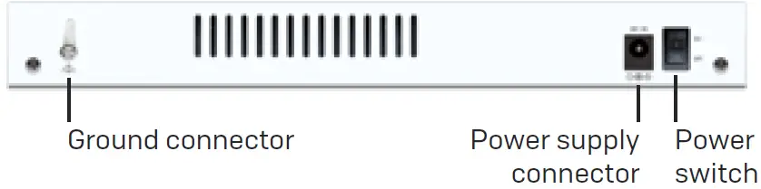
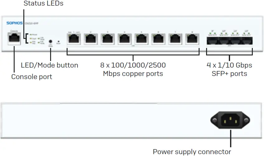
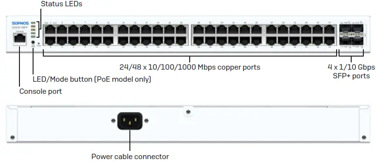
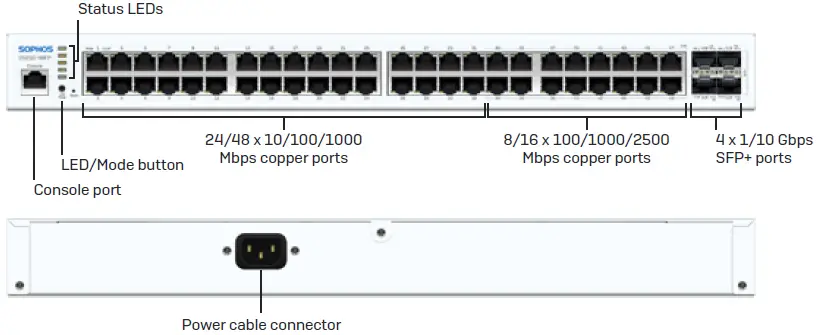
Appliance images: front and back
- CS101-8x*
- CS210-8FP
- CS110-xx**
- CS210-24/48FP***
- CS101-8FP model shown, other models may vary
- CS110-48FP model shown, other models may vary
- CS210-48FP model shown, other models may vary
Mount and Power Up the Switch
Mount the switch in the rack
If you want to mount the switch in a rack, please use the supplied rackmount kit for this device where available. For instructions on how to mount your switch, please see the Operating Instructions under www.sophos.com/get-started-switch
Connect the power cable and turn on the switch
Connect the power supply (where available) and/or supplied power cable to the switch and turn it on (if unit has a power button). After a few seconds, the Power LED will start blinking and the switch will boot. This process should take just a few minutes. After the boot-up is complete the Power LED will turn to solid green.
Connect Grounding Cable (CS101-8x models only)
If ethernet cables are run between buildings or if the switch is used in a high lightning exposure area, connect a safety ground wire to the grounding screw to provide additional protection from electrical shock. If unsure of your electrical ground, consult an electrician.
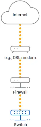
Connect the Switch to your Network
Connect any port on the switch to the next-hop ethernet switch or Sophos Firewall. After powering on, the switch will boot and attempt to get an IP address from a DHCP server (either from the Sophos firewall or another DHCP server in your network).
If the switch is unable to get an IP address from a DHCP server and is not registered in Sophos Central within 15 minutes, it will use a default IP address 172.16.16.239. To manually configure your switch, adjust the network settings of your administration PC (PC/laptop) so that it is on the same network as the switch. For example:
- IP Address: 172.16.16.230
- Netmask: 255.255.255.0
Connect your Administration PC/laptop to port 1 of the switch.
Open a browser and enter the IP address of the switch: https://172.16.16.239 and complete the setup and configuration. If you want to attempt registration with DHCP again, correct the fault that prevented the switch from getting a DHCP assigned IP address and power cycle the switch either manually or via the switch management interfaces (CLI or HTTPS web interface).
Please Note: If the switch is still unable to retrieve an IP address from the DHCP server it will use the default IP address 172.16.16.239.
Set Up the Switch
- Sign in to Sophos Central at central.sophos.com
If you don’t yet have a Sophos Central Account, please create one. - Register the switch in your Sophos Central account by entering the serial number.
Note: After powering on the switch, there is a 15-minute window to register the switch in Sophos Central. If the network administrator does not register the switch within this time period, the switch will have to be either hard rebooted or rebooted using the local web interface. - After the switch is registered in Sophos Central, it is upgraded to the latest firmware version.
Sign in to your Sophos Switch
Sophos provides users an option to sign in to the switch for advanced configuration. The advanced options can be configured in the on-box web interface of the switch or through its command line interface (CLI).
- Register the switch in Sophos Central as mentioned in the above section.
- An IP Address will be assigned to the switch from either Sophos Central or the DHCP server
- Open a web browser on your computer enter the IP address and press enter.
- In order to access the CLI or the web interface of the switch after registering it in Sophos Central, use the default credentials with the username as “admin” and the unique password for this switch.*
Managing the Switch via the Console Port
- Connect the switch console port (not available on CS101-8/8FP models) to a computer using the console cable provided.
- Launch any terminal emulation program, e.g., PuTTy
- Select the COM port, and use the following settings:
- Baud Rate: 115200
- Data bits: 8
- Parity: None
- Stop bits: 1
- Flow Control: None
- Press Enter on your keyboard to connect to the CLI.
- Sign in using the username “admin” and the unique password for this switch.*
- The unique password is printed on a sticker (see picture to the right) affixed to the chassis of the switch and on an additional sticker in the packaging materials.
Connecting Power over Ethernet (PoE) Devices
All ports on PoE-capable switches can provide Power over Ethernet (PoE) to a connected PoE device which conforms with the 802.3af (max. 15.4W) or 802.3at (max.30W) standards. Each port can provide up to a maximum of 30 Watts.
Please note: If the total power consumption of all PoE-powered devices exceeds the power budget of the switch, the PoE Max LED will turn on. The port with the highest number and the lowest priority (according to the per-port priority settings configured), will no longer receive power and the PoE Mode LED for that port will be turned off. To avoid such situations, Sophos recommends calculating the number of connected devices based upon their max. power consumption (see table “interfaces” above).
LED Status
| Status LEDs | |||
| Power | Green | Solid | Power On |
| Off | Power Off | ||
| Fault | Amber | Solid | Error |
| Off | Normal Behavior | ||
| PoE Max | Amber | Solid | The power requested by PoE devices exceeds total PoE limit of the switch. No additional devices can be powered. |
| Off | Additional PoE devices may still be powered | ||
| LAN Mode* | Green | Solid | The left LED on RJ45 ports indicates Speed |
| PoE Mode* | Green | Solid | The left LED on RJ45 ports indicates PoE status |
- By pressing the “LED mode” button you can switch the meaning of the left LED on each RJ45 port (labeled with “mode”) between LAN Mode and PoE Mode.
| LEDs on each RJ45 Ethernet Connector | |||
| LK/AT (Link/Activity) (Right LED) | Green | Solid |
|
| Flashing | The port is sending or receiving network data. | ||
| Off |
| ||
| CS101-xx Models | |||
| Speed (Left LED) [on PoE models: LED Mode button not pressed] | Green | Solid | Ethernet port is operating at 1000 Mbps. |
| Off | Ethernet port is operating at 100 0r 10 Mbps (if LK/AT LED is active). | ||
| 1G Ports on CS110-xx and CS210-xx Models | |||
| Speed (Left LED) [on PoE models: LED Mode button not pressed] | Green | Solid | Ethernet port is operating at 1000 Mbps. |
| Amber | Solid | Ethernet port is operating at 100 Mbps. | |
| Off | Ethernet port is operating at 10 Mbps (if LK/AT LED is active). | ||
| 2.5G Ports on CS210-xx Models | |||
| Speed (Left LED) [on PoE models: LED Mode button not pressed] | Green | Solid | Ethernet port is operating at 2500 Mbps. |
| Amber | Solid | Ethernet port is operating at 1000 or 100 Mbps. | |
| Off | Ethernet port has no link | ||
| CS101-8FP (PoE) Models only | |||
| Mode (Left LED) [LED Mode button pressed] | Green | Solid | PoE switch provides power to the port |
| Off | No power is provided to the port | ||
| CS110/210 P/FP (PoE) Models only | |||
| Mode (Left LED) [LED Mode button pressed] | Green | Solid | PoE switch provides power to the port |
| Amber | Solid | Error | |
| Off | No power is provided to the port | ||
| LEDs on each SFP/SFP+ Ethernet Connector | |||
| LK/AT (Link/Activity) | Green | Solid |
|
| Flashing | The port is sending or receiving network data. | ||
| Off |
| ||
| CS110/CS210-xx Models | |||
| Speed (Left LED) | Green | Solid | Ethernet port is operating at 10 Gbps. |
| Amber | Solid | Ethernet port is operating at 1 Gbps. | |
Please note: Additional LED blinking sequences not listed above indicate specific maintenance processes such as firmware updates. For more information, please check additional Sophos documentation resources.
Support and Documentation
For more information and technical support, please visit www.sophos.com/en-us/support or contact your local Sophos reseller.
United Kingdom Sale
s Tel.: +44 (0)8447 671131
Email: [email protected]
North American Sales
Toll Free: 1-866-866-2802
Email: [email protected]
Sales DACH
(Deutschland, Österreich, Schweiz)
Tel.: +49 (0) 611 585 8-0
Tel.: +49 (0) 721 255 16-0
E-Mail: [email protected]
Australia and New Zealand Sales
Tel.: +61 2 9409 9100
Email: [email protected]
Japan Sales
Tel.: +81 3 3568 7550
Email: [email protected]
China Sales
Tel.: +86-10-6567 5820
Email: [email protected]
Shanghai Sales
Tel.: +86-21-32517160
Email: [email protected]
© Copyright 2021. Sophos Ltd. All rights reserved.
Registered in England and Wales No. 2096520, The Pentagon, Abingdon Science Park, Abingdon, OX14 3YP, UK Sophos is the registered trademark of Sophos Ltd. All other product and company names mentioned are trademarks or registered trademarks of their respective owners.
References
 Sophos Central
 Service and Support
 Sophos Cybersecurity as a Service: Cybersecurity als Komplett-Service
-
Support Overview | Sophos
-
Introducción al soporte | Sophos
-
Service and Support
-
Présentation du support | Sophos
-
Service and Support
-
サポート概要 | Sophos
-
Visão geral de suporte | Sophos
-
Cybersecurity as a Service Delivered | Sophos
 Service and Support


