condair RCC-NA 0-10 V Digital Wall Humidistat
This document covers the operation and installation instructions for the following Condair digital humidistat:
Kit No. Component No. Description
2597928 1510142 0-10 V Digital Wall Humidistat
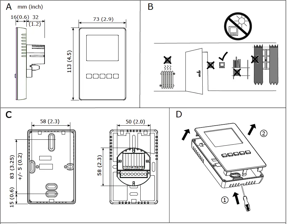
Mounting and Installation
Location:
Mount the humidity controller Condair RCC-NA in a protected and easy accessible place at least 1.5 m above the floor to the wall (mounting on flush-mounting or surface-mounting box). Observe the following placement notes:
- Do not place Condair RCC-NA in niches, behind, curtains, etc.
- Do not place the Condair RCC-NA near heat sources, within the area with direct air draft or direct sunlight.
Installation:
Refer to installation overview in section 2.
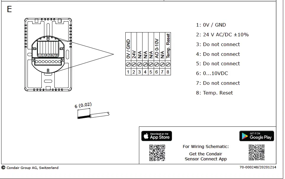
- Open the screw of the housing and remove mounting plate with the connecting unit.
- Connect wires of the connection cable to the terminals according to the wiring diagram.
- At the place of location fix mounting plate (plastic screw facing downwards) with two screws to the flush-mounting or wall-mounting box (see dimensional drawing).
- Carefully snap housing onto the mounting plate and fix it with the screw (do not tighten screw too much).
Note: We recommend using 18-gauge wire, and maximum <100 ft distance from the unit.
Installation overview
Wall Humidistat LCD Display
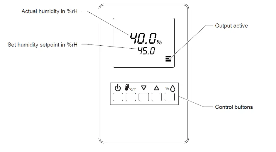
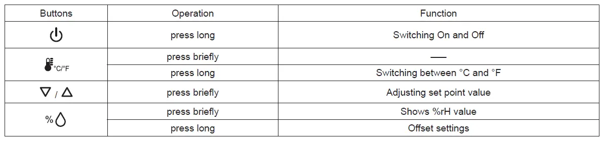
Fig. 1: Wall Humidistat LCD Display and function of control buttons
Configuration
Using keypad, set specified humidity. For general health and comfort, a humidity setting of 50% is recommended.
Error Messages
Err 1: Sensor element in the device is not properly inserted or defective. Insert the sensor element correctly or replace it.
Err2, 3 & 4: Hardware or memory problem. Replace device.
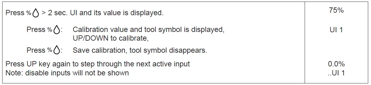
Sensor Calibration
Sensor inputs can be calibrated if needed
Setting Parameters to Configure the Controller
The control operation is defined by parameters set using the standard operation terminal. There are two levels:
- User/display parameters (password 0009)
- Control parameters (password 00241)
How to change the parameters:
- Press < >/< > button simultaneously for three seconds. The display will show firmware version and revision number.
- Press the < > button to start login. The small digits show “CODE”.
- Select correct code (password) using < > and < > buttons.
Note: Code to access user parameters is “0009”. The access codes are fixed and cannot be changed. - Press the < > button after selecting the correct code.
- Once logged in with “0009”, the user/display parameters are displayed immediately.
- Select the parameters with the < > or < > button. Change a parameter by pressing the < > button. The symbol is displayed to indicate that the parameter may be modified. Use < > or < > button to adjust the value.
- After you are done, press < > button to save the new value and return to the selection level (symbol disappears after selection is saved). Pressing < > button without pressing < > button will discard the value and return without saving.
- Press the < > button to leave the menu. The unit will return to normal operation if no button is pressed for more than 5 minutes.
User Parameters (Password 0009)
Table 1: User Parameters
| Parameter | Description | Range | Default |
| UP 00 | Enable change of operation modes | ON, OFF | ON (Enabled) |
| UP 01 | Enable change of setpoints | ON, OFF | ON (Enabled) |
| UP 02 | State after power failure: 0 = Switched OFF, 1 = Switched ON, 2 = state before power failure | 0, 1, 2 | 2 |
| UP 03 | Celsius or Fahrenheit: ON = Fahrenheit, OFF = Celsius | ON, OFF | OFF (Celsius) |
| UP 04 | Select contents of small digits in standard mode (00 = OFF): 01 = Setpoint 02 = Humidity Sensor 03 = External Temperature Sensor | 00…03 | 01 |
Control Parameters (Password 0241)
Note: Only experts should change these settings! See user parameter for login procedure!
Table 2: Output Configuration
| Parameter | Description | Range | Default |
| CP 00 | Minimum setpoint limit in humidification mode | 0..100% | 10% |
| CP 01 | Maximum setpoint limit in humidification mode | 0..100% | 90% |
| CP 02 | Start delay for fans (Time the fan runs before control output starts) | 0…255 s | 10 s |
| CP 03 | Stop delay for fan (Time the fan keeps running after control output stops) | 0…255 s | 90 s |
Table 3: Temperature Setback Configuration – *For humidity control only
| Parameter | Description | Range | Default |
| CP 04 | Enable temperature setback OFF = Temperature set back is disabled ON =Temperature setback is enabled | ON, OFF | OFF |
| CP 05 | Setpoint limit at full setback | 0..100 % | 20 % |
| CP 06 | Lower temperature limit: Outside temperature with maximum setback The setback will be equal to the minimum setpoint limit | -40…60°C -40…160°F | -30 °C (-22°F) |
| CP 07 | Upper temperature limit: Outside temperature at begin of setback | -40…60°C 40…160°F | 0 °C (32°F) |
| CP 08 | Number of seconds taken into account to calculate the average input signal Low value = fast response High value = slow response | 0…100 | 30 |
Product Specification
| Power Supply | Operating Voltage Power Consumption Terminal Connections | 24 V AC 50/60 Hz ± 10 %, 24 VDC ± 10 % Max. 3 VA For wires 0.34…2.5 mm2 (AWG 24…12) |
|
Sensor Probe (Humidity Sensor) | Measuring element Range Accuracy Hysteresis Repeatability Stability | Capacitive measuring element 0…100 % RH ± 3.0 % at 25 °C ± 1% ± 0.1% < 0.5% / Year |
|
Signal Outputs | Analog Outputs Analog Signal Resolution Maximum Load | AO1 0…10 VDC or 0…20mA 39 mV or 0.0078 mA 10 mA (at 0…10 VDC) 20 mA (at 0…20mA) |
| Environment | Operation Temperature Humidity | IEC 721-3-3 0…50°C 32…122°F) ˂95 %rH not condensing |
| General | Housing Materials Mounting Plate Weight (including packaging) | ABS Galvanized Steel 260 g (9.2oz) |
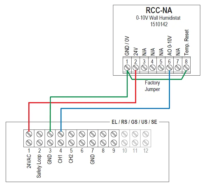
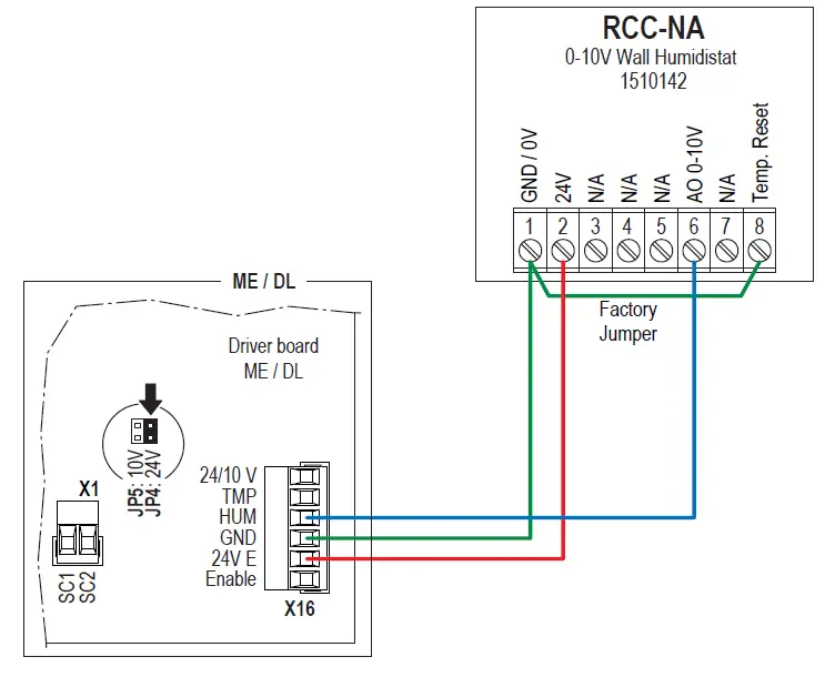
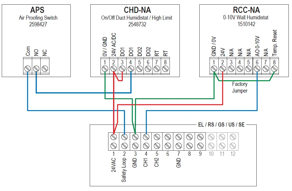
Wiring Diagrams
Wiring diagram RCC-NA for RS, EL, GS, US and SE
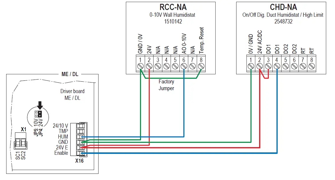
Wiring diagram RCC-NA for DL and ME
Wiring diagram RCC-NA with CHD-NA and APS for RS, EL, GS, US and SE
Wiring diagram RCC-NA with CHD-NA for DL and ME