RAIN HARVESTING WDIG10 100mm First Flush Delta In Ground Diverter Installation Guide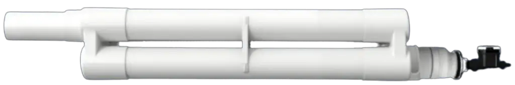
PRODUCT DETAILS
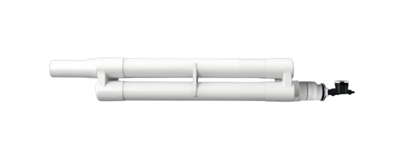
A high volume first flush diverter, designed specifically for inground applications. Divert the dirtiest water and transform your rain harvesting system from “wet” to “dry” with this large volume inground first flush diverter.
The unique manifold design uses standard 100mm or 4″ pipe to create a high capacity storage and diversion chamber for your first flush. Using these smaller pipe sizes makes it easier to source pipe and assemble the system, when compared to using large diameter pipe on traditional high volume diverters.
| Code | Size | Country |
| WDIG10 | 100mm 4″ | Global |
Installation
WHAT’S IN THE BOX?
- Delta chamber end caps x 2
- Cage/Seat & Ball
- Chamber support spacer
- 100mm (4”) socket reducer
- Transparent Rapid Release Exit Funnel
- Electronic Release Valve
- Primary Filter Screen
TOOLS/MATERIALS YOU MAY REQUIRE
- Tape measure
- Marker pen
- Saw
- File
- Priming fluid
- Solvent weld glue
- Screws/Anchors
- Screw driver
- Drill
- 100mm (4”) pipe
INSTALLATION
- It is a requirement to install a rain head upstream of any down pipe feeding the Delta In-Ground First Flush. Large debris must not enter the First Flush chambers to prevent blockages and damage to the Electronic Release Valve
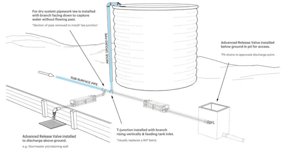
- Select an installation point for your Delta In-Ground First Flush. Your diverter must be installed on a slope (minimum 5% or 1 in 20) to ensure it drains after each rainfall event. Your first flush T-junction should be at the lowest point in your Rain Harvesting sub-surface pipework or at a location to allow for easy installation and draining of the Electronic Release Valve. The T-junction can also be installed to replace the 90° bend at the base of the vertical pipe feeding your rainwater tank. If the Rain Harvesting sub-surface pipework is not part of a “wet” system, the T-junction will need to be installed with the branch below the main line and a 90° bend to direct first flush of water to the Delta. The outlet must also be accessible for maintenance and inspection. This may be achieved by running pipe to a location aboveground or installing an access pit (e.g. stormwater pit) (refer to Figure 1 for suggested installation locations).
- Remove Delta First Flush components from packaging and lay out parts ready for assembly
- Determine chamber length using the calculation chart provided, based on your Rain Harvesting roof collection area and considered pollution level (see Figure 8 – Delta Diversion Chamber Calculator).
- Using a tape measure, mark, cut and deburr 6 equal lengths of 100mm (4”) pipe to be used as the Chamber Pipes
NOTE: It is critical that all the Chamber Pipes are exactly equal length. It is also recommended to apply a small chamfer to the outside ends of the six Chamber Pipes to improve ease of insertion into the Chamber Sockets.
Suggested Installation Orientations
- Using priming fluid, clean all internal sockets of both Delta End Caps and each external ends of the six Chamber Pipes.
- Apply solvent weld glue to the Max Chamber adaptor and glue it onto the upper end of your diversion chamber. If you aren’t using the Max Chamber adaptor you can disregard this step.
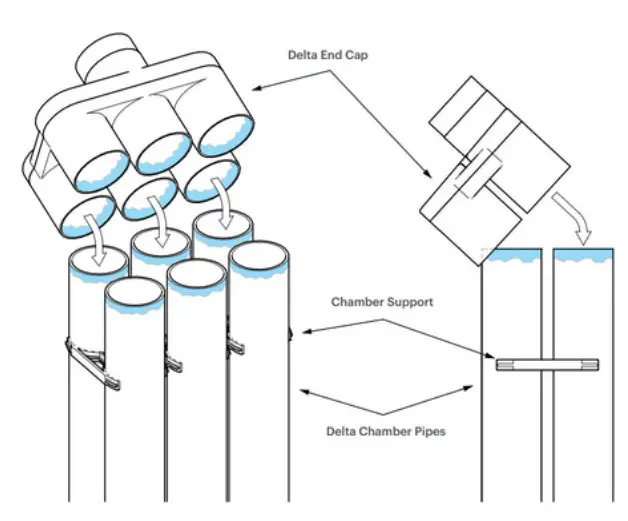
- Working with one Delta End Cap, apply solvent weld glue internally to a Chamber Socket and then externally to one of the Chamber Pipes. Bring the two together ensuring the pipe is inserted fully into the socket and hold until firm. Repeat this step for all remaining pipes until all six Chamber Pipes are glued into one Delta End Cap.
NOTE: All sockets of the Delta End Cap are stepped internally. The inner socket is for use with 100mm UPVC pipe and the outer socket for 4” Sch. 40 pipe. Only apply solvent weld glue to the socket relating to the pipe in use. - Slide the Chamber Support Spacer over the open end of the Chamber Pipes and position approx. 200mm (8”) from the unglued end.
Delta In-Ground Inlet/Outlet Position
- Working quickly, apply solvent weld glue to each of the six internal Chamber Sockets of the remaining Delta End Cap and then externally to the six Chamber Pipes. Quickly bring the Delta End Cap together with the six pipes by first aligning three pipes and sockets on one side and then rolling onto the remaining three pipes. Using some force, push the Delta End Cap down onto the Chamber Pipes ensuring the pipes enter the socket fully and hold in position until secure (Figure 3 – Delta Diagram).
Delta Diagram
- Move the Chamber Support Spacer down the Chamber Pipes to approximately the half way position ensuring the pipes will be supported evenly.
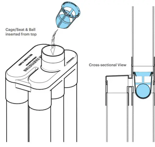
- Insert Cage/Seat & Ball into the inlet (upstream) Delta End Cap, ensuring it is oriented correctly (Figure 4).
Inserting the Cage/Seat and Ball/
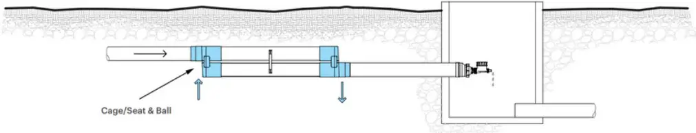
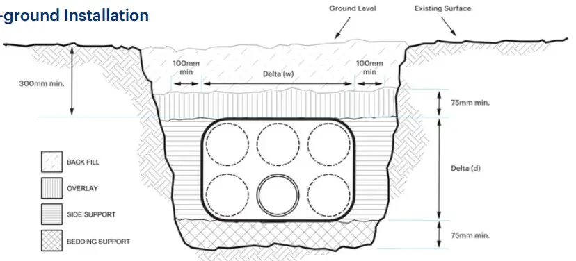
- Excavate the installation location for the T-junction, assembled Delta Chamber and adjoining pipe work. Trenches should be wide enough to include a minimum of 75mm bedding and overlay support and a minimum of 100mm side support. In non-trafficable areas allow for a minimum of 300mm cover (measured from the top of the Delta/pipe to the ground surface). See Figure 5 for installation. For further information we recommend using AS3500.2:2018 as a guide.
Delta In-ground Installation
- Using a T-junction as a template, measure the pipes at your chosen installation point and cut to create space for the T-junction. Using priming fluid and solvent weld glue, install the T junction and fittings as required and extend pipe work ready to install your Delta.
- Place your Delta in position and using priming fluid and solvent weld glue connect your Delta to the extended pipe work ensuring you push the pipe hard up against the Cage/Seat & Ball. Backfill your Delta using bedding sand capable of passing through a 2mm sieve, as per State and Local Government guidelines and information provided in the previous step.
- The Transparent Rapid Release Exit Funnel needs to be installed in an accessible location (above ground where the ground slopes away or in a stormwater pit for access. Using a min. 170mm of 100mm pipe (3.5″ of 4″ pipe) and solvent weld glue, attach the 100mm90mm (4”-3”) Socket Reducer (100mm/4” End Coupling) to the outlet (downstream) Delta End Cap. Screw the Transparent Rapid Release Exit Funnel onto the threaded end of the Socket Reducer.
- Install the Primary Filter Screen, Transparent Rapid Release Exit Funnel, and Electronic Release Valve by following the instructions in Figure 6.
Installing and setting up the Electronic Release Valve
6a. Insert the Primary Filter into the end of the First Flush chamber. It should fit snuggly into the socket on the end of the pipe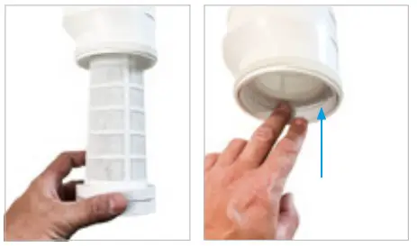
6a. Insert the Primary Filter into the end of the First Flush chamber. It should fit snuggly into the socket on the end of the pipe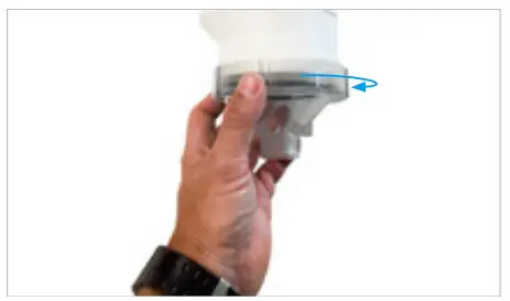
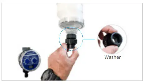
6c. Attach the Electronic Release Valve by first installing the 25mm x 20mm (1″ x 3/4″) reducing adaptor and washer to the 25mm (1″) thread of the screw cap.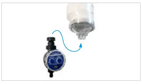
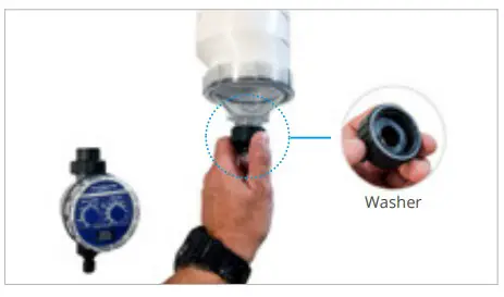
6d. Remove the union from the valve and attach to the reducing adaptor with 20mm (3/4″) washer in place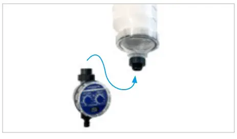
6e. Attach the valve at the union and orientate dial for easy access.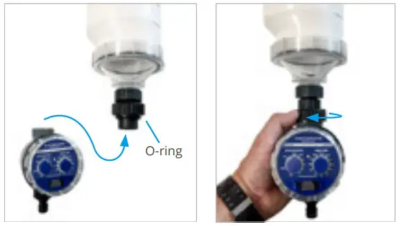
6f. Remove the waterproof cover from the Electronic Release Valve.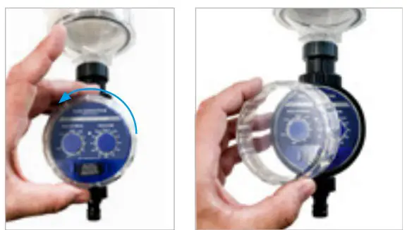
6g. Ensure the reset interval and drain time control knobs are in the “RESET” and “CLOSED” positions. Carefully slide out the battery box and install two new 1.5-volt AAA batteries.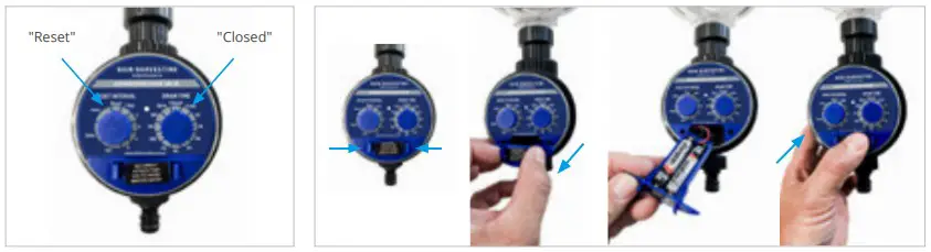
6h. Test the unit by turning the drain time knob to the “OPEN” position. You should hear the sound of the motor within 5 seconds. Turn the drain time knob back to the “CLOSED” position ready for setting.
NOTE: If you do not hear the sound of the motor, check that the batteries are installed correctly.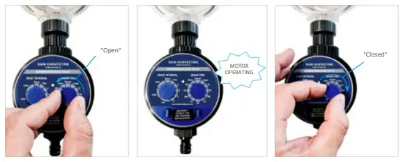
6i. Ensure that the reset interval and drain time knobs are in the “RESET” and “CLOSED” positions.
NOTE: The first time you program the Electronic Release Valve it will not begin to operate until after a time delay equal to the setting of the reset interval knob you select. The Electronic Release Valve starts to keep time when you set it. It is important that you set the timer at the hour you want it to operate. For example, if you want the Electronic Release Valve to operate at 07:00AM, you must physically set it at 07:00AM.
Set your reset interval and drain time according to the tables in Figure 6, then replace the battery box cover. A long reset interval will mean that the first flush diversion chamber empties less frequently, leading to higher rainwater yield. A short reset interval will mean that the first flush diversion chamber empties more frequently, resulting in a lower water yield.
Electronic Release Valve Reset and Drain Time Settings
Suggested Reset Setting :Pollution Level
Recommended drain time setting :Approx. First Flush chamber size
| 1 day | Very high | 5 minutes | 20 litres | 5.3 gallons | |
| 2 days | Very high | 10 | 40 | 10 | |
| 3 days | High | 20 | 80 | 20 | |
| 4 days | Medium | 30 | 120 | 30 | |
| 5 days | Medium | 45 | 180 | 50 | |
| 1 week | Low | 60 | 240 | 60 | |
| 2 weeks | Very Low | 75 | 30 | 80 | |
| 4 weeks | Very Low | 100 | 400 | 100 | |
| 125 | 500 | 130 | |||
| 150 | 600 | 160 |
Delta Diversion Chamber Calculator
| AUSTRALIA | |
| Chamber Volume in Litre | Total Length in Millimetres |
| 30 | 185 |
| 40 | 374 |
| 50 | 564 |
| 60 | 753 |
| 70 | 942 |
| 80 | 1132 |
| 100 | 1511 |
| 110 | 1700 |
| 120 | 1889 |
| 130 | 2079 |
| 140 | 2268 |
| 150 | 2458 |
| 180 | 3026 |
| 200 | 3405 |
| USA | |
| Chamber Volume in Gallons | Total Length in Inches |
| 8 | 4 |
| 10 | 10 |
| 12 | 16 |
| 14 | 22 |
| 18 | 34 |
| 20 | 40 |
| 24 | 52 |
| 28 | 64 |
| 32 | 76 |
| 40 | 100 |
| 50 | 130 |
| 56 | 148 |
| 72 | 196 |
| 80 | 220 |
NOTE:
2 x Delta End Caps hold approximately 20.24 litres. (Excluding the pipe sockets of chamber.)
The above figure is total volume of delta end cap excluding the liquid contained within the 6x pipe chambers.
NOTE:
2 x Delta End Caps hold approximately 6.52 gallons. (Excluding the pipe sockets of chamber.)
The above figure is total volume of delta end cap excluding the liquid contained within the 6x pipe chambers.
POLLUTION FACTOR FOR THE ROOF
| MINIMAL POLLUTION | SUBSTANTIAL POLLUTION |
| DIVERT 0.5L PER M Open field, no trees, no bird droppings, clean environment | DIVERT 0.5L PER M Leaves and debris, bird droppings, various animal matter, e.g. dead insects, skinks, etc. |
The above quantum are the results of preliminary testing. Individual site analysis and field testing is required to more accurately assess the quantum to be diverted in each individual case.
| MINIMAL POLLUTION | SUBSTANTIAL POLLUTION |
| DIVERT 0.0125 GALLONS PER FT Open field, no trees, no bird droppings, clean environment | IVERT 0.05 GALLONS PER FT Leaves and debris, bird droppings, various animal matter, e.g. dead insects, skinks, etc. |
The above quantum are the results of preliminary testing. Individual site analysis and field testing is required to more accurately assess the quantum to be diverted in each individual case.
DIVERSION FACTOR FOR A FIRST FLUSH WATER DIVERTER
| MINIMAL POLLUTION | SUBSTANTIAL POLLUTION |
| M ROOF AREA X POLLUTION FACTOR = LITERS TO BE DIVERTED | |
| Example for a minimal polluted roof of 100m 100 x 0.5 = 50 Litres to be diverted | Example for a heavily polluted roof of 100m 100 x 2 = 200 Litres to be diverted |
DIVERSION FACTOR FOR A FIRST FLUSH WATER DIVERTER
| MINIMAL POLLUTION | SUBSTANTIAL POLLUTION |
| FT ROOF AREA X POLLUTION FACTOR = GALLONS TO BE DIVERTED | |
| Example for a minimal polluted roof of 1000ft 1000ft x 0.0125 = 12.5 gallons to be diverted | Example for a minimal polluted roof of 1000ft 1000ft x 0.5 = 50 gallons to be diverted 2 2 2 2 2 |
Product Specifications
First Flush Delta In-Ground
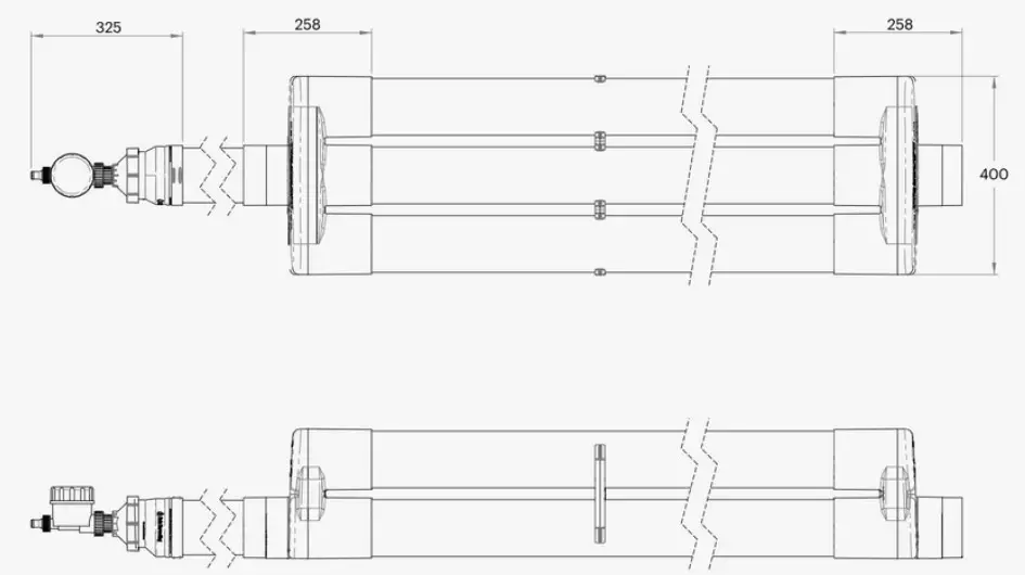
Dimensions & Pipe Fittings
| COUNTRY | CODE | A | B | C | D | E |
| Global | WDIG10 | 100 F | 400 | 258 | 304 | 261 |
| 4″ SCH40 F | 15.7″ | 10.2″ | 12″ | 10.3″ |
All dimensions are in mm unless otherwise stated
Fitting guide:
F = Female / Socket Fitting (Pipe fits inside)
M = Male / Spigot Gitting (Pipe size, fits into a socket)
Maintenance
It’s important to ensure that your first flush diverter outlet remains clear of any debris. If your outlet becomes blocked, the chamber will not empty and the first flush of water will not be diverted when it rains.
To ensure the flow of water out through your Electronic Release Valve, periodically remove from the Transparent Rapid Release Exit Funnel to check for any build-up of matter. Remove primary filter plus ball, and clean if required.
Periodically check that the Electronic Release Valve batteries have charge. This is indicated by the flashing light.
To protect your Electronic Release Valve from freezing or “winterising”, remove the timer prior to the first frost or freeze and store it indoors until spring. Remember to remove the batteries from the battery compartment.
For best results and minimal maintenance, rain heads with 0.955mm aperture mesh such as Leaf Eater Rain Heads must be installed upstream of the Delta First Flush to limit the entry of debris that can reach your diverter.

A common misconception about collecting rainwater is that all you need is a roof, a tank and some rain. This ‘tanking’ approach cannot always be relied on to deliver the volume – or quality – of water that you require. That is where we can help.
With some thought, your rain harvesting system can provide you with cleaner water and lots of it. Whether you’re completely reliant on tank water or wanting to keep the garden green, our simple steps will help you achieve your goal.
The Rain Harvesting approach to rainwater collection involves using tested and proven products to make quality rainwater available for use in and around your property. You don’t need much to get started and you will be surprised how easy it is to get the most out of your rainwater system.
How can we help you?
DISCLAIMER This product specification is not a complete guide to product usage. Further information is available from Rain Harvesting Pty Ltd and from the Installation and Operating Instructions. This specification sheet must be read in conjunction with the Installation and Operating Instructions and all applicable statutory requirement. Product specifications may change without notice. © Rain Harvesting Pty Ltd
For more information or to find out
how we can help, just give us a call on
+61 7 3248 9600
Or visit our website at
rainharvesting.com


