ST UM3144 Evaluation Board For L9678 Airbag And Battery Cut-Off IC
Introduction
The L9678-S-EVB evaluation board is an evaluation board designed to provide to the user a platform for the evaluation of the L9678P or L9678P-S devices. The board provides all the main input/output capabilities needed to properly drive all IC inputs and outputs and to provide diagnostic functionalities
Hardware description
The L9678-S-EVB evaluation board has been developed to evaluate the L9678P or L9678P-S devices and test all their functionalities.
Its main features are:
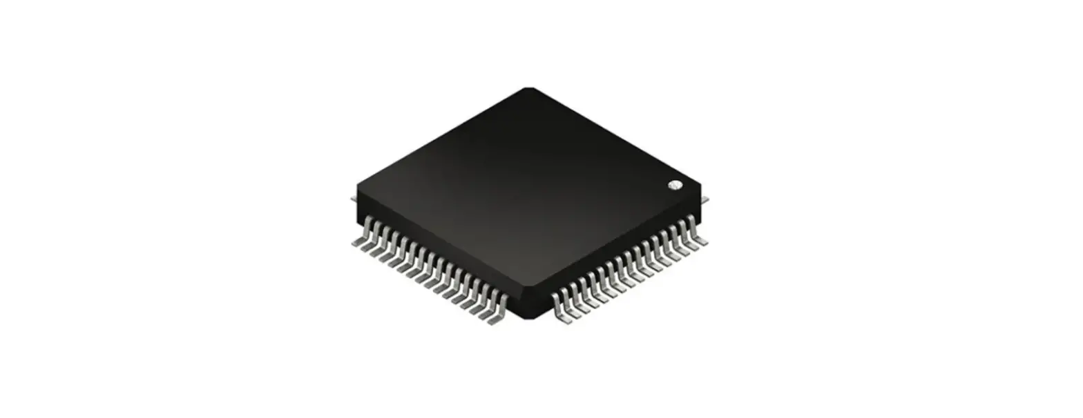
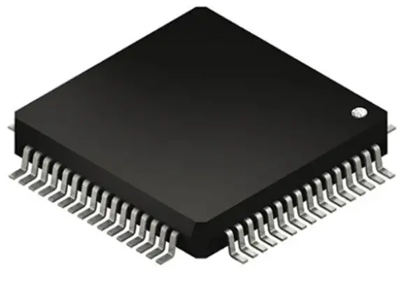
- L9678P/L9678P-S placed into a socket allowing an easy change of the samples
- Possibility to solder L9678P/L9678P-S directly on the PCB
- Total accessibility to all pins through test points
- Presence of jumpers to fix the desired set up configuration
- Possibility to interface the board with SPC56P-Discovery board
L9678-S-EVB evaluation board
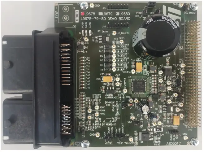
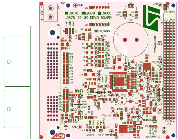
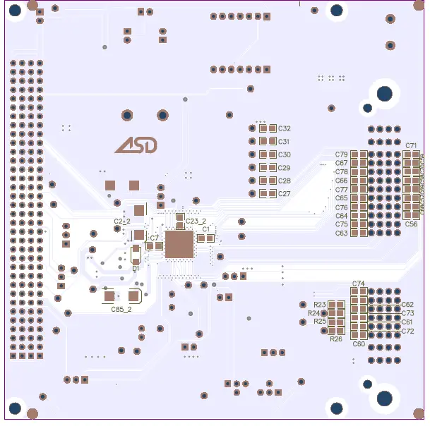
Board layout
Assembly Top
Assembly Bottom
Jumpers and connectors description
On Table 1 the name of each jumper on the board is listed while their default setting (closed or open) is reported in green; the name of the connectors and test points present on the board is also remarked
Jumpers and connectors description
| # | Name | J = Jumper C = Connector | Function | Closed | Open |
| J1 | PGND | J | Connection of PGND to GND | Power ground connected to common ground(1) | – |
| J2 | WDT | J | To disable the watchdog timer | Watchdog disabled | Watchdog enabled(1) |
| J3 | J | To set VCC to 5 V or to 3.3 V | 1-2 closed: VCC connected to VDD3V3 2-3 closed: VCC connected to VDD5(1) | – | |
| J4 | VBAT | C | Battery voltage | – | – |
| J5 | IGN | J | To wake-up the device | Device waked-up(1) | Device not waked-up |
| J6 | J | Connection of L9678 RESET pin to GPIO or RESET pin of μC | 1-2 closed: RESET_L96xx connected to uC RESET pin 2-3 closed: RESET_L96xx connected to μC GPIO0 pin | – | |
| J7 | SAFING INPUT | J | Connection of safing FET gate to VSF directly or through MUN5332DW | 1-2 closed: safing FET enabled via uC 2-3 closed: safing FET always enabled | Safing FET disabled |
| J8 | J | To discharge the ER capacitor | ER capacitor shorted to ground | ER capacitor charged(1) | |
| J9 | J | To connect the ER cap negative to ground | Cap negative connected to ground(1) | Cap negative not connected to ground | |
| J10 | HEADER34X4 | C | To connect the L9678 demo board to discovery board | – | – |
| J11 | J | To connect ISOK bus | 2-3 closed: ISO bus enabled(1) | – | |
| J12 | J | Not used for L9678 | – | ||
| J13 | BGND | J | Connection of BGND to GND | Boost ground connected to common ground(1) | – |
| J15 | J | Reserve voltage diagnostic (VRES) | VRES can be connected to ERBOOST, VBAT or VSUP | Reserve voltage is not diagnosed | |
| J16 | J | Not used for L9678 | |||
| J17 | J | Connection of VCC to VCC_Micro | VCC connected to VCC_Micro | VCC and VCC_Micro disconnected(1) | |
| J18 | C | SPI interface connector | – | – | |
| J19 | C | SPI interface connector | – | – | |
| J20 | AGND | J | Connection of AGND to GND | Analog ground connected to common ground(1) | – |
| J28 | J | RSU power supply | 1-2 closed: RSU power supply connected to VSUP(1) 2-3 closed: not used for L9678 | No RSU power supply |
| # | Name | J = Jumper C = Connector | Function | Closed | Open |
| J29 | J | To connect the ER cap positive to VER | Cap positive connected to VER(1) | Cap positive not connected to VER | |
| J30 | C | Airbag standard connector | – | – |
Default condition.
Test point list
| Designator | Name | Function |
| TP1 | FENH | FENH monitoring |
| TP2 | FENL | FENL monitoring |
| TP3 | COVRACT | COVRACT monitoring |
| TP4 | ACL | ACL monitoring |
| TP5 | ARM1 | ARM/ARM1 monitoring |
| TP6 | WDT | WDT monitoring |
| TP7 | ERBOOST | ERBOOST monitoring |
| TP8 | uc_SAFING | Monitoring of μC safing FET enable |
| TP9 | VIN monitoring | |
| TP10 | VDD3P3 | VDD3P3 monitoring |
| TP11 | BVSUP | BVSUP monitoring |
| TP12 | SAFING OUTPUT | SAFING OUTPUT monitoring |
| TP13 | VSUP | VSUP monitoring |
| TP14 | SS01 | SS01 monitoring |
| TP15 | SS23 | SS23 monitoring |
| TP16 | SS45 | SS45 monitoring |
| TP17 | SS67 | SS67 monitoring |
| TP18 | SS89 | SS89 monitoring |
| TP19 | SSAB | SSAB monitoring |
| TP20 | CVDD monitoring | |
| TP21 | VBATMON monitoring | |
| TP22 | BVVD5 | BVVD5 |
| TP23 | VDD5 | VDD5 monitoring |
| TP24 | SYNCBOOST monitoring (only L9679/80) | |
| TP25 | Monitoring of Q5 collector voltage | |
| TP26 | Monitoring of μC diagnostic enable | |
| TP27 | SATBCK monitoring | |
| TP28 | VCC monitoring | |
| TP29 | RSU4 monitoring | |
| TP30 | RSU3 monitoring | |
| TP31 | RSU1 monitoring | |
| TP32 | RSU0 monitoring | |
| TP33 | GND | GND monitoring |
| TP34 | CS_RS | CS_RS monitoring (only L9680) |
| TP35 | SPI_CS | SPI CS monitoring (only L9679/80) |
| TP36 | GND | GND monitoring |
| TP37 | GND | GND monitoring |
| TP38 | GND | GND monitoring |
| Designator | Name | Function |
| TP39 | GND | GND monitoringC |
Revision history
Document revision history
| Date | Version | Changes |
| 02-Mar-2023 | 1 | Initial release. |
IMPORTANT NOTICE – READ CAREFULLY
STMicroelectronics NV and its subsidiaries (“ST”) reserve the right to make changes, corrections, enhancements, modifications, and improvements to ST products and/or to this document at any time without notice. Purchasers should obtain the latest relevant information on ST products before placing orders. ST products are sold pursuant to ST’s terms and conditions of sale in place at the time of order acknowledgment. Purchasers are solely responsible for the choice, selection, and use of ST products and ST assumes no liability for application assistance or the design of purchasers’ products. No license, express or implied, to any intellectual property right is granted by ST herein. Resale of ST products with provisions different from the information set forth herein shall void any warranty granted by ST for such product. ST and the ST logo are trademarks of ST. For additional information about ST trademarks, refer to www.st.com/trademarks. All other product or service names are the property of their respective owners. Information in this document supersedes and replaces information previously supplied in any prior versions of this document. © 2023 STMicroelectronics – All rights reserved


