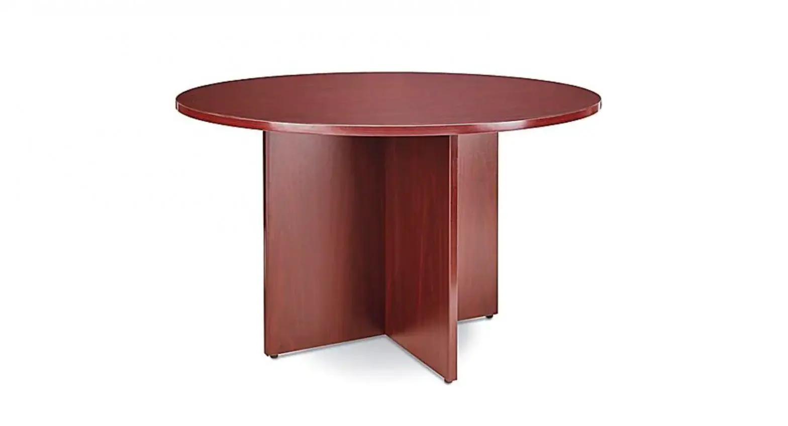
ULINE 48′ Round Conference Table Instructions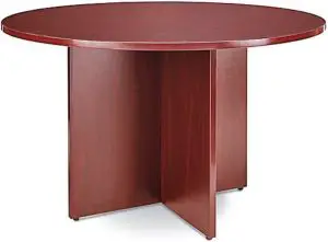
TOOLS NEEDED
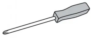
- Phillips Screwdriver

- Drill (Optional)

- Two Person Assembly Required


PARTS
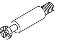
- Camlock Pin x 10

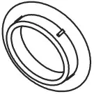
- Camlock x 10

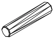
- Dowel x 3

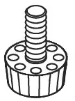
- Floor Glide x 4

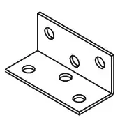
- L-Bracket x 4

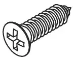
- Screw x 29 #4 5/8″

- Deep Camlock Cap x 10


ASSEMBLY
NOTE: Assemble on a smooth, non-marring surface to avoid scratching the table.
- Check that all parts are included.
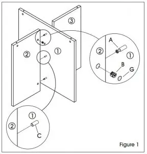
IMPORTANT: The arrow on the camlock (B) must point toward the camlock pin (A) for proper alignment. Turn camlock (B) clockwise until it locks with pin (A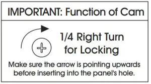
- Insert four camlocks (B) into holes on leg panel (2). Insert four camlock pins (A) and two dowels (C) in center leg (1). Fit center leg (1) and leg panel (2) together and turn each camlock (B) clockwise until it locks. Cover each camlock (B) with a deep camlock cap (G). (See Figure 1)
- Repeat to attach leg panel (3) to center leg (1). (See Figure 1)

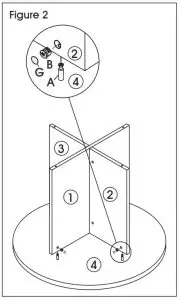
- Place tabletop (4) upside down on a smooth, non-marring surface. Insert four camlocks (B) into corresponding holes on leg panels (1, 2 and 3). Insert four camlock pins (A). With two people, place the assembled base on the tabletop (4). Turn each camlock (B) clockwise until it locks. Cover each camlock (B) with a deep camlock cap (G). (See Figure 2).

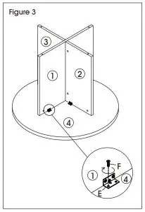
- Attach an L-Bracket (E) to each side of the center leg (1) and secure to tabletop (4) using four #4 5/8″ screws (F) per bracket. Tighten screws with Phillips screwdriver. (See Figure 3)
- Attach an L-Bracket (E) to leg panel (2) and secure to tabletop (4) using four #4 5/8″ screws (F). Tighten screws with Phillips screwdriver. Repeat to attach leg panel (3) to tabletop (4). (See Figure 3)

NOTE: Ensure two L-Brackets connect center leg (1) to the tabletop (4) and one L-Bracket connects each leg panel (2 and 3) to the tabletop (4).
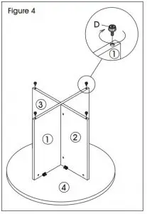
NOTE: L-Bracket holes can be started with drill (optional). - Mount floor glides (D) on center leg (1), and leg panels (2 and 3). Floor glides (D) can be adjusted to compensate for uneven floors. (See Figure 4)

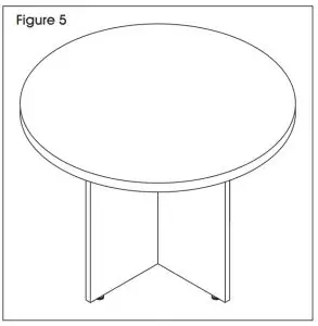
- With two people, turn table over and set it upright. (See Figure 5)

Contact: 1-800-295-5510
Website: uline.com


