![]()
www.AKCP.com
WT-AQS (Wireless Tunnel Air
Quality) Sensor Manual
Copyright © 2021, AKCP
Introduction
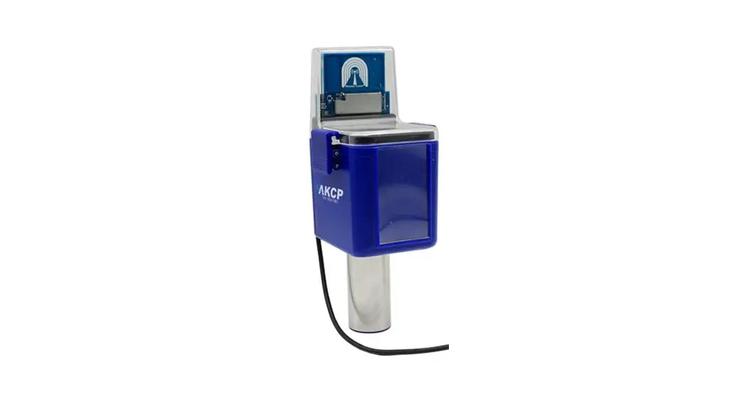
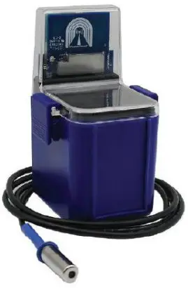
The Wireless Air Quality Sensor combines Air Particles, Metal Oxide Gasses (MOx), Temperature, and Humidity in a single sensor including Metal Oxide Gases (MOx)
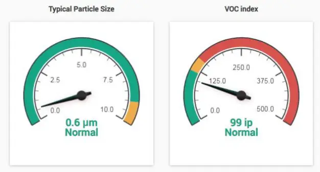
This sensor detects various Metal Oxide (MOx) gases, displaying the value as a VOC Index.
Examples of these gases are :
– Acetone (eg. paints and glues)
– Toluene (eg. furniture)
– Ethanol (eg. perfume, cleaning fluids)
– Hydrogen Sulfide (eg. decaying food)
– Benzene (eg. Cigarette smoke)
The VOC Index is a logarithmic scale that is relative to the typical indoor gas composition over the past 24 hours. With a range of 0 to 500, the typical value for a normal environment is 100. Values greater than 100 indicate worsening air quality with a higher concentration of metal oxide gases over the past 24 hours. Values lower than 100 indicate improving air quality.
Air Particles
Detection for 5 different sizes. PM0.5, PM1.0, PM2.5, PM4 and PM10. The sensor is able to measure the mass concentration of particles in the PM1.0 to PM10 range and particle number concentration in the PM0.5 to PM10 range. The typical particle size is also measured. This measurement is based on the average size of the current sample.
An air particle sensor is utilized during indoor air quality (IAQ) assessments of clean rooms and workplaces. The specific type of particles is not detected, but it identifies the quantity or mass of airborne particles. These air particles could be sourced from :
– Exhaust smoke
– Airborne dust particles
– Pollen
Airborne pollutants can be a health hazard, and result in sneezing, headaches, asthma, and so on. In addition, during many agricultural and industrial processes, airborne dust can be a serious hazard forming combustible dust clouds.
These sensors must be connected to our AKCP WTG (Wireless Tunnel Gateway), or our AKCP wireless base units in order to function. It is easily configured in the base unit’s web user interface which will be covered later in this manual. These sensors cannot be connected to any third-party units or wireless devices other than our AKCP units.
Compatibility
This sensor is compatible with all WTG or Wireless AKCP base units only.
It is not compatible with the securityProbe, sensorProbe+, or sensorProbe units.
Note: A wired type AQS may be available in the future for the sensorProbe+ base units.
Please check with our support team on this.
Sensor Type & Technical Specifications
(also found in the sensor datasheet):
| Air Particle Sensor | Particle Mass Concentration Particle Number Concentration Typical Number Concentration |
| Particle mass concentration range | PM 1.0/2.5/4/10: 0 – 500 pg/m3 |
| Mass concentration size range | PM1.0 : 0.3 to 1.0 μm PM2.5 : 0.3 to 2.5 μm PM4: 0.3 to 4.0 μm PM10 : 0.3 to 10.0 μm |
| Mass concentration precision | * PM1 and PM2.5 0 to 100 pg/m3: ±10 pg/m3 100 to 1000 pg/m3 : ±10 % measured value. * PM4 and PM10 0 to 100 pg/m3 : ±25 pg/m3 100 to 1000 pg/m3 : ±25 % measured value. |
| Particle number concentration range | PM 0.5/1/2.5/4 10: 0 – 1500 #/cm3 |
| Number concentration size range | PM0.5 : 0.3 to 0.5 μm PM1.0 : 0.3 to 1.0 μm PM2.5 : 0.3 to 2.5 μm PM4: 0.3 to 4.0 μm PM10 : 0.3 to 10.0 μm |
| Typical Particle size | 0.1 to 10 pm |
| VOC Index Sensor | Index of Air Quality VOC index, MOx based gas sensor |
| Range | 0 to 500, with 100 as typical air quality < 100 = better air quality > 100 = worse air quality |
Note: VOC Index visualizes VOC events on a logarithmic scale, and relative to the typical indoor gas composition during the recent 24th. This means that level “typical” refers to the typical conditions of the environment with low and high VOC backgrounds. The scale does not represent absolute concentrations. VOC Index notifies end-users or air treatment devices when air pollution changes.
Environmental Conditions
| Temperature | |
| Measurement Range | -40°C to +75°C 40°F to +167°F |
| Measurement Resolution | 0.1°C increments 0.2°F increments |
| Measurement Accuracy | Typical: * ±0.3 from -40°C to +75°C * ±0.4 from -40°F to +167°F Maximum: * ±0.4 at -40°C and ±0.4 at +75°C * ±0.7 at -40’F and ±0.7 at +167°F |
| Humidity | |
| Measurement Range | 0 to 100% Relative Humidity (RH) |
| Measurement Resolution | 1%RH increments, 0.01%RH sensor reading |
| Measurement Accuracy | ±2%RH @25°C |
| Gateway Sensor Count | 16 (3+13) |
| Status Indication | Led indication for – Mode – Status – RSSI |
| Operating Environment | Temperature: Min. -35°C – Max.80°C Humidity: Min. 20% – Max. 80% (Non-Condensing) |
| LoRa (R) Radio Regional plans | – EU868 : 863-868Mhz, Max TX Power +14dBm, Duty Cycle 1% – US915: 903-915Mhz, Max TX Power +17dBm -AS923 : 920 -925Mhz, Max TX Power +14dBm, Duty Cycle 1% – KR920 (Korea) : 922-923Mhz, Max TX Power +14dBm, Duty Cycle 1% – IL917 (Israel) : 915-917Mhz , Max TX Power +14dBm, Duty Cycle 1% |
| Certification | CC Part15C. CE EN300220-2 |
| Power source | Requires external micro-USB 5V power source Optional 12V input (customer order) |
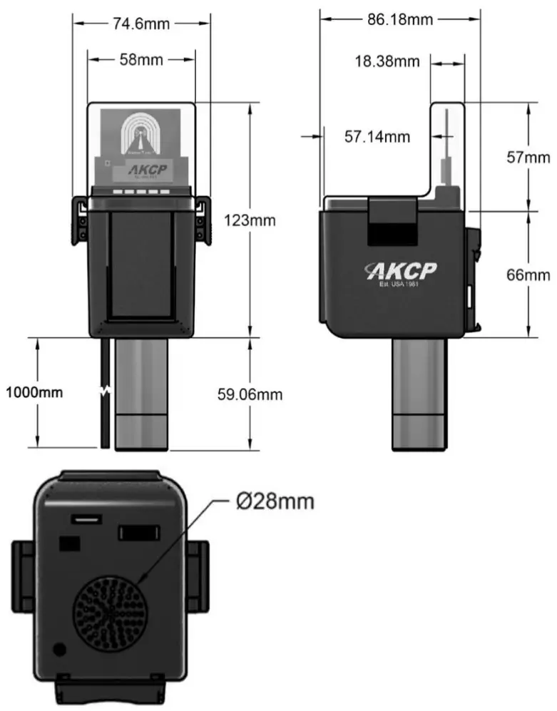
Sensor Technical Drawing & Dimensions
Connecting the Sensor & Configuration
Important Note: Please refer to the WTG manual on how to set up this unit that is also on our support website portal.
How to add the Wireless Sensor (BOS/WTS) to the WTG
Wireless sensors have the advantage of easy installation with no communication cables or power required. These sensors communicate with the WTG using radio frequency signals, and you need to pair them with the WTG to get their data.
As an example, we will use the Wireless Temperature & Humidity Sensor (WTS-TH).
This type of wireless sensor will monitor temperature and humidity levels, can log and graph data over time, and you can configure real-time alerts when user-defined sensor thresholds are exceeded. It can also be used as a data logger, with the readings buffered and then synchronized to the gateway when in range. The IP66 rated enclosure provides weatherproofing for use in outdoor environments.
The WTS-TH can be ordered with the sensor on cable up to 15ft in length (as in the picture on the left). This allows you to place the radio module in a convenient location with the sensor placed in a precise position. The sensor can be battery powered with an estimated 10-year life, or connected to a USB power source.
Adding the wireless sensor
First make sure that your wireless sensor is in a RUN mode in order to complete the sensor pairing: press and hold the sensor’s button for 1-2 seconds. The wireless sensor’s LED will light up briefly. Then open the WTG unit’s WebUI. Click on the Add Wireless Device icon to begin.
Depending on the sensor type, different configuration options will be shown. We’ll only focus on the WTS-TH in this manual. However, there are the screenshots in the last section of this manual that refer specifically to the Air Quality Sensors.
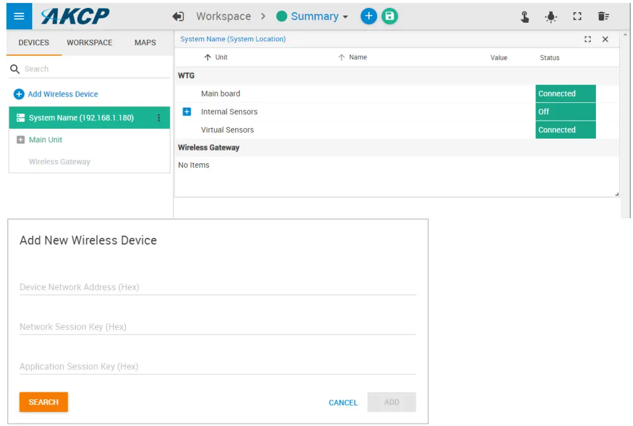
You may either input the wireless key details manually or use one of the automated methods detailed below.
USB
If you connect the wireless sensor directly to the WTG unit’s USB port, it will be automatically detected. You can add it when you see the popup window:
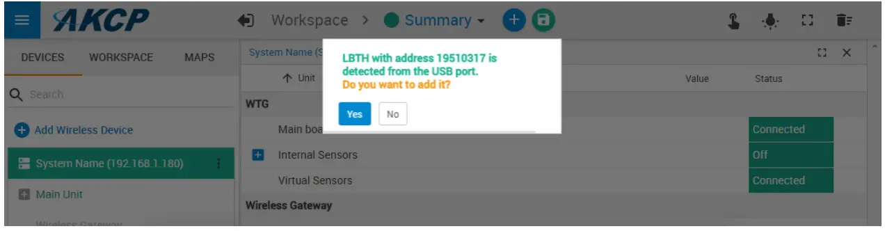
Otherwise, when you click Add Wireless Device and the sensor is connected to the USB port, its parameters will be automatically detected:
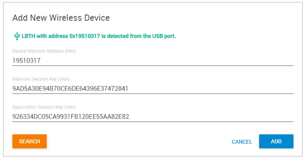
Click Add to add it to WTG.
Search
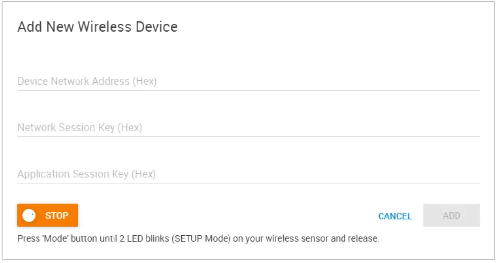
The wireless search method can be used to automatically find a wireless sensor.
Click Add Wireless Device then click on the Search button on the lower-left corner.
Press and hold the button on the wireless sensor until the LED begins to blink (SETUP mode).
After it’s detected, click on Add to add it to WTG.
Note: make sure that your wireless sensor is in a RUN mode in order to complete the sensor pairing: press and hold the sensor’s button for 1-2 seconds. The wireless sensor’s LED will light up briefly.
After a new sensor has been added, you will notice a warning triangle next to it:
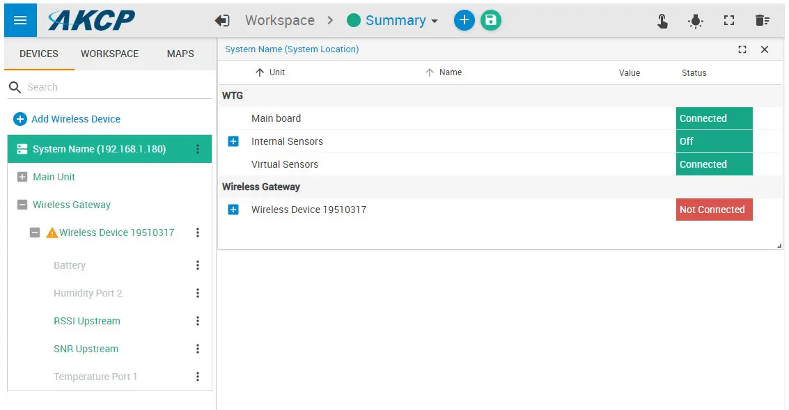
This indicates that the sensor still requires sync (pairing) with the WTG.
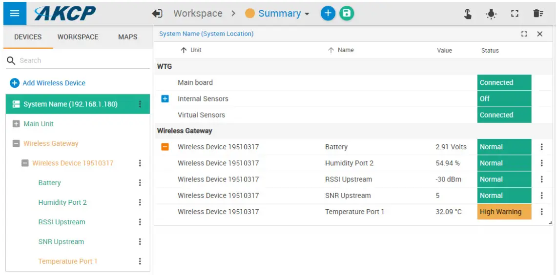
Normally the sync will be done automatically, and after that, the sensor readings should display correctly:
Further sensor configuration
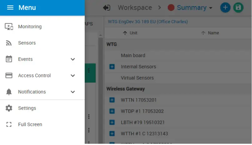
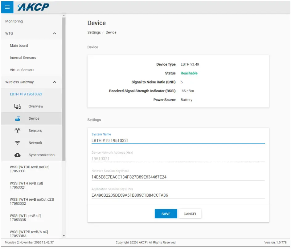
Access the menu on the top left corner and go to the Sensors page. The wireless sensors can be managed from this menu.
Here you can rename the sensor for easier identification:
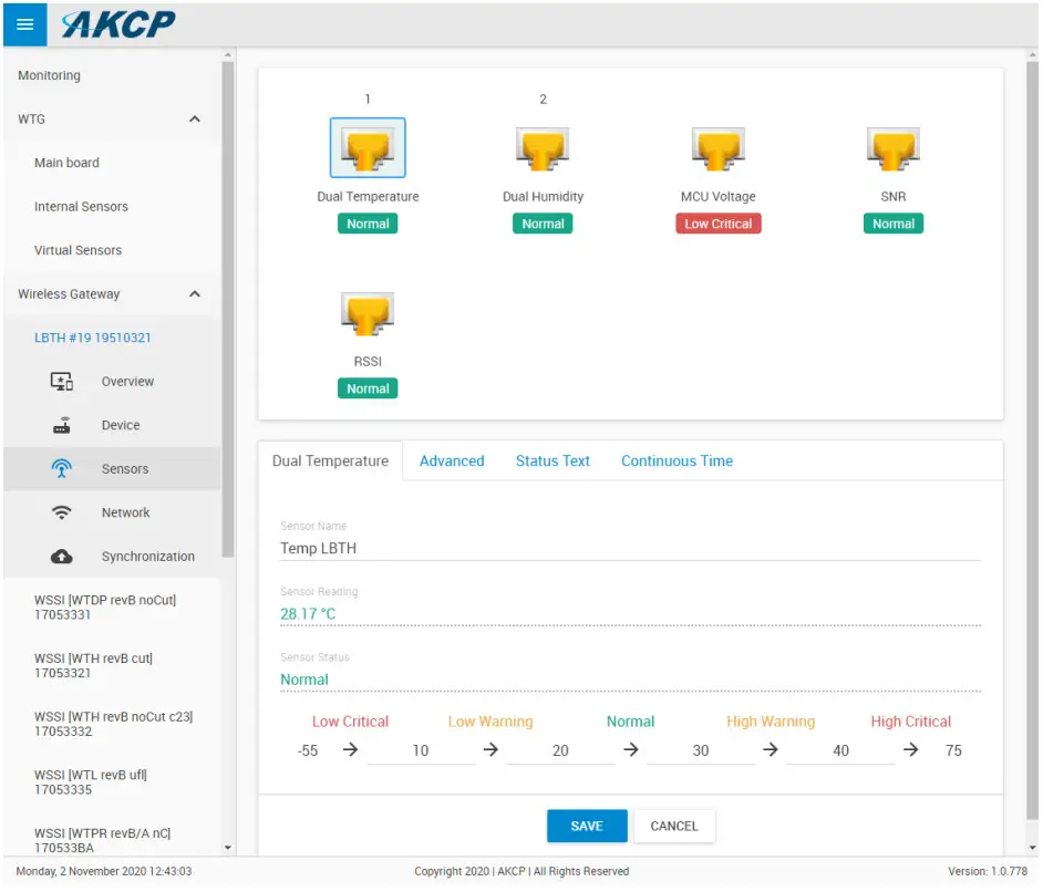
Adjust the sensor reading thresholds:
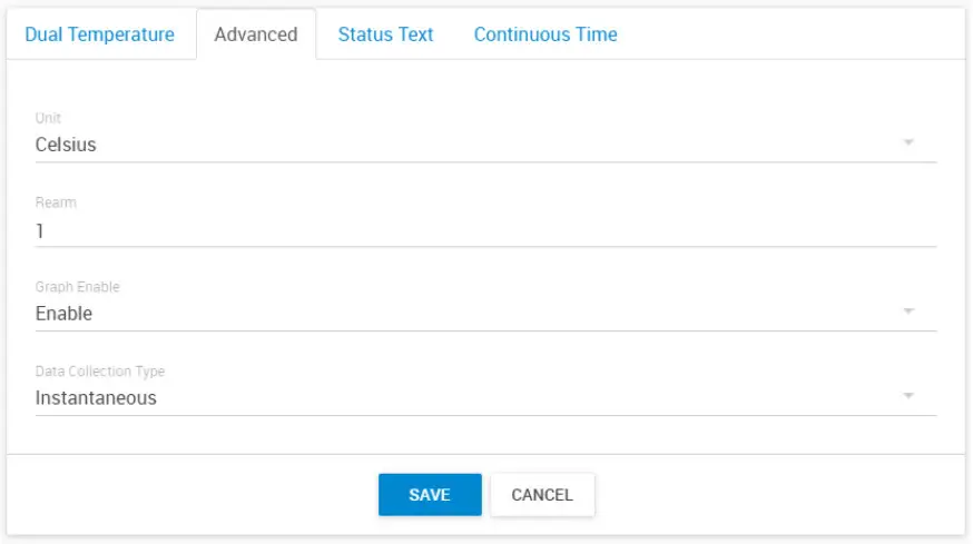
Access further fine-tuning of the readings:
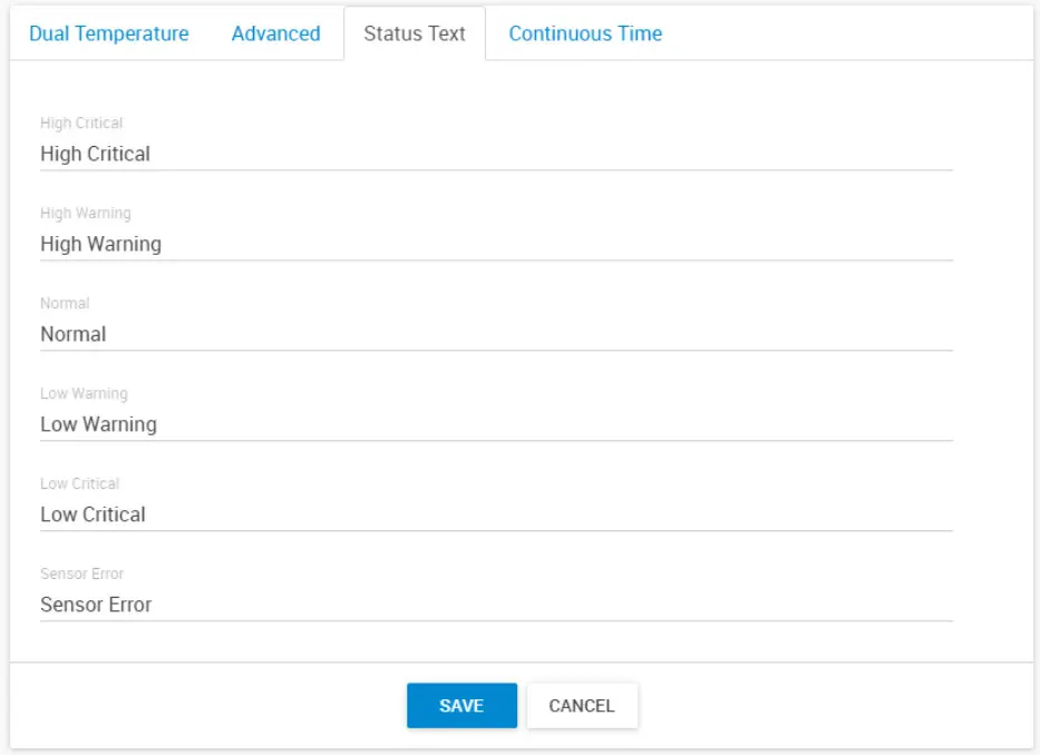
Change the sensor reading status texts for each status:
Adjusting the continuous-time for each sensor status:
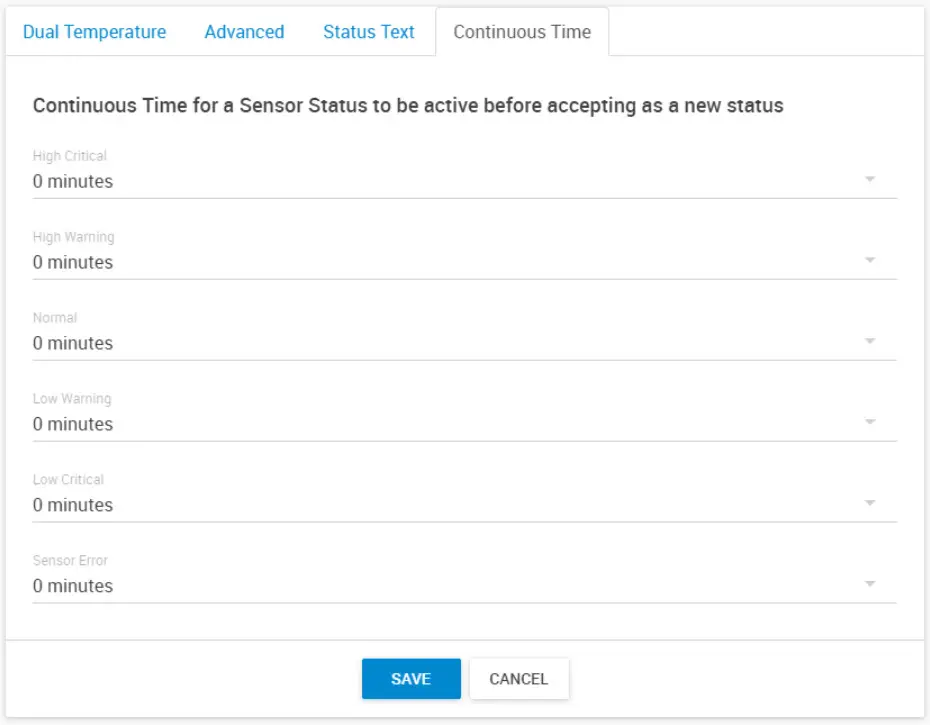
For the switch type sensor, it’s working the same as the feature we have on the wired AKCP sensors.
For the analog sensor type, you can set the number of polling (we display in time, polling number * polling interval) before accepting the status.
Adjusting the wireless network settings per sensor (take note of the warnings regarding battery life):
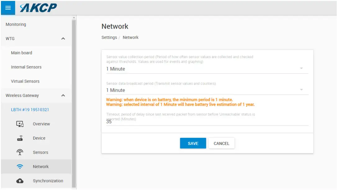
Important: the graph sampling period will use the “sensor value collection period” parameter. See details below in the Graphing feature overview.
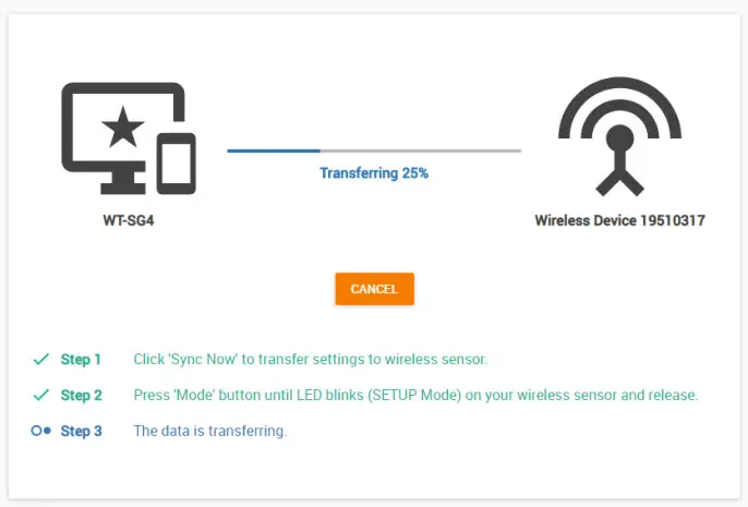
After making any changes, you would need to re-sync the sensor.
This ensures that all configured settings will be sent to the sensor. Without sync, your new thresholds won’t be applied.
Note: the sensor settings can also be synced automatically the next time that the sensor broadcast a packet, but doing a manual sync is a faster way when the sensor is close at hand.
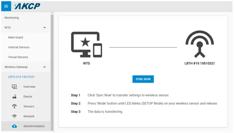
Click the Sync Now button and follow the instructions on-screen (switch the sensor to SETUP mode).
We recommend changing the used LoRa wireless channel if you are in an environment with high radio traffic that affects sensor reading.
Go to Settings menu/Wireless/Wireless Settings:
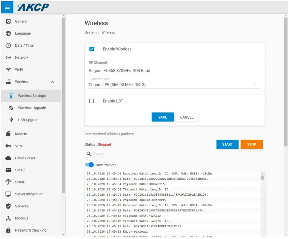
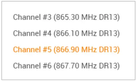
Choose a different channel that has less radio traffic.
The available list of channels will depend on your country’s radio frequency regulations.
Important: After changing the channel, you will need to manually re-sync your wireless sensors!
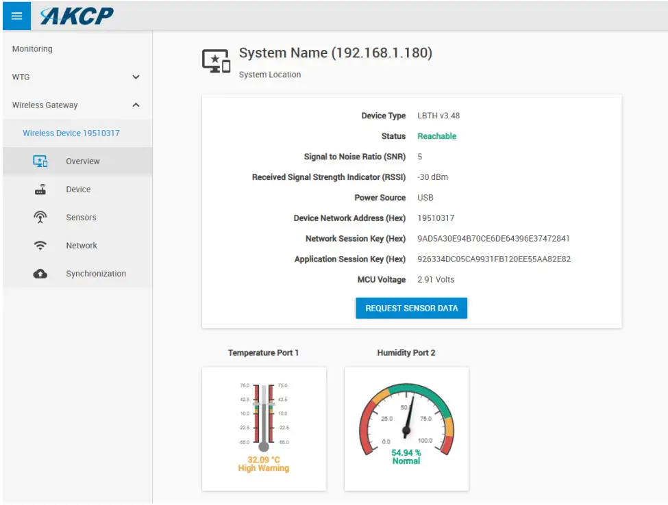
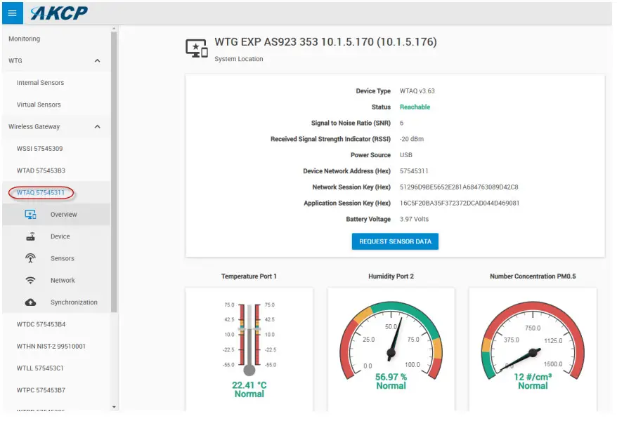
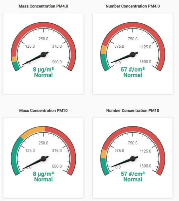
Specific View for the Air Quality Sensors
Please contact [email protected] if you have any further technical questions or problems.
Thanks for Choosing AKCP!


