BATHOLOGY Spectrum 360 Steam Sauna Bath LED Light Bar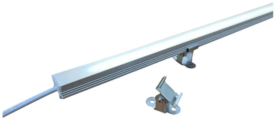
Specifications
| Figure 1: Table 1: Spectrum 360 Specifications | |||
| Kelvin: 3500 K | Operating Temp: -13 F to 195 F | Max Run: 4 Light Bars / 20 Linear Feet | IP Rating: IP67 |
| LED light bar is suitable for use in sauna environments. LED light bar is IP67 rated for outdoor saunas. LED light bar is not for commercial use. | |||
| Operating Voltage (VDC) | Power Consumption (Watts) | Lumens | Dimensions (in.) (with Flush Clips) | Dimensions (in.) (with Adjustable Clips) | |
| Brilliance 360-12 LED White | 24 | 2.4 | 270 | 3/4W x 12L x 9/16H | 3/4W x 12L x 1-1/4H |
| Brilliance 360-24 LED White | 24 | 5.4 | 596 | 3/4W x 24L x 9/16H | 3/4W x 24L x 1-1/4H |
| Brilliance 360-36 LED White | 24 | 8.3 | 921 | 3/4W x 36L x 9/16H | 3/4W x 36L x 1-1/4H |
| Brilliance 360-48 LED White | 24 | 11.3 | 1,246 | 3/4W x 48L x 9/16H | 3/4W x 48L x 1-1/4H |
| Brilliance 360-60 LED White | 24 | 14.2 | 1,571 | 3/4W x 60L x 9/16H | 3/4W x 60L x 1-1/4H |
| Figure 2: Table 2: Dimmer Switch Specifications | ||||||
| Operating Voltage | Maximum Wattage | Dimming Range | Diameter | Depth | Rough-in Cutout | IP Rating |
| 24 VDC | 72 Watts | 1-100% | 3/4″ Body / 15/16″ Trim | 13/16″ | 3/4″ | IP 20 |
| Figure 3: Table 3: Power Supply Specifications | ||||
| Operating Voltage | Output Voltage | Power Consumption | Nominal Amperage | Dimensions |
| 120 VAC | 24 VDC | 90 Watts | 1.3 Amps | 2.36W x 5.70L x 1.25H |
![]() Warning
Warning
Do not hot swap any of the components of this system. Hot swapping can cause damage to the system or harm to the user.
![]() Warning
Warning
Do not modify any components of this system. Modifying components of this system can cause system failure or harm to the user.
![]() Important
Important
Brilliance LED fixture should not be installed directly above Sauna Heater or in a location where Brilliance fixture will exceed maximum temperature of 195°F.
![]() Important
Important
For sauna interior mounting, the dimmer switch should not be located within a 30″ radius of the heat source and should be a maximum of 36″ above the finished floor.
![]() Warning
Warning
Locating the dimmer switch too close to the heat source or too high in the room could cause damage to the switch.
Connections Diagram
Figure 4: Connections Diagram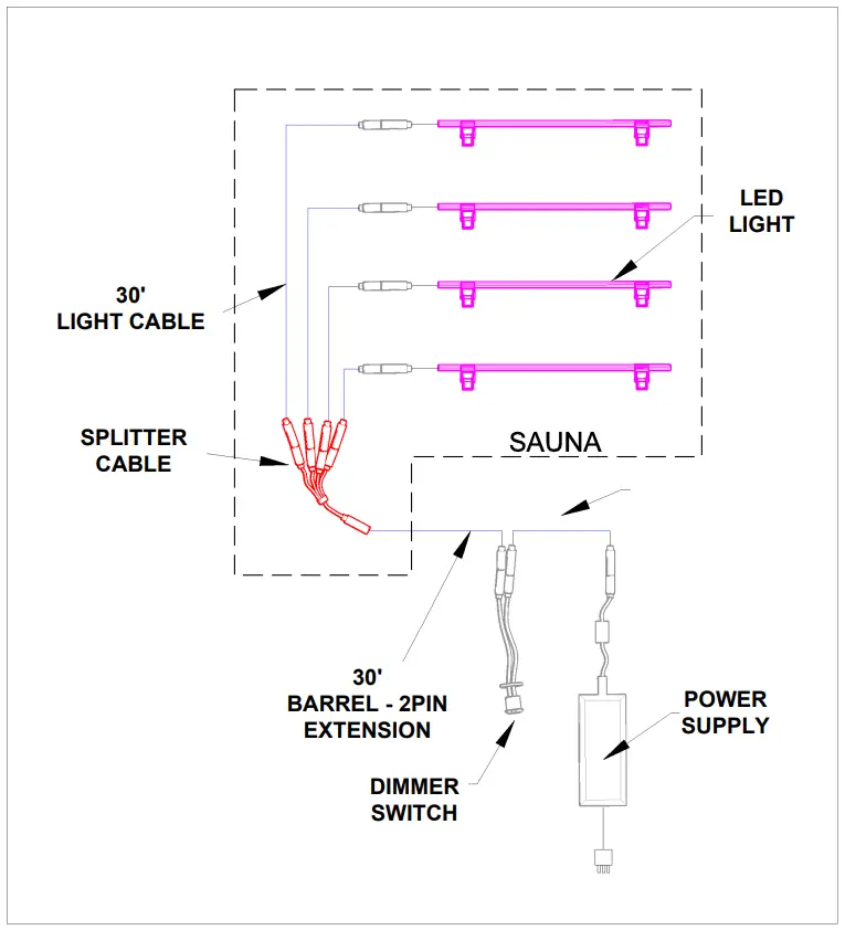
Connections Diagram 2
Figure 5: Connections Diagram 2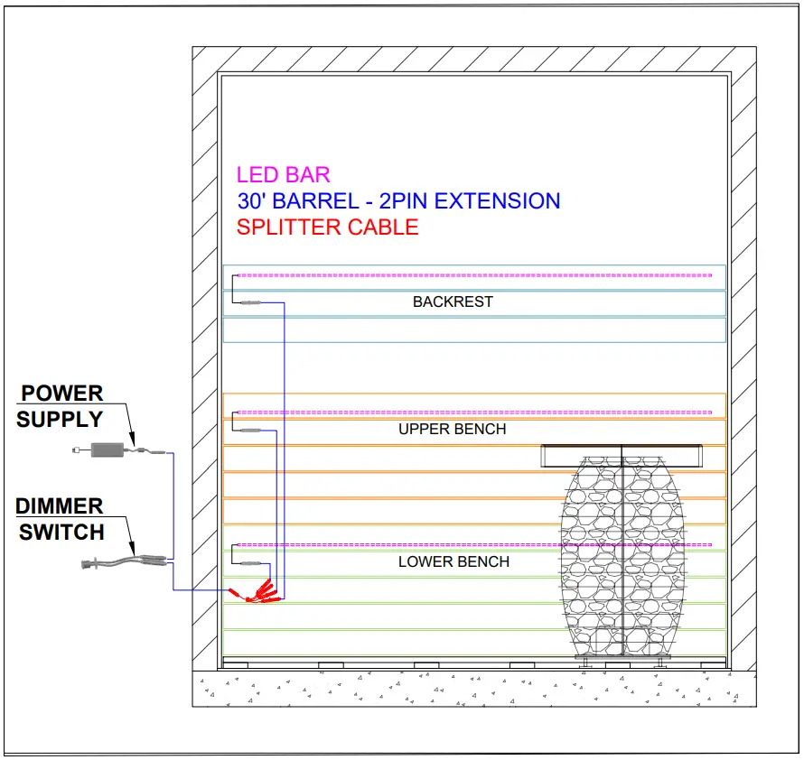
![]() Warning
Warning
The dimmer should only be mounted using the methods described in this manual. Mounting the dimmer using methods other than those described in this manual could cause damage to the dimmer or harm to the user.
Dimmer Switch Mounting Instructions
Drill a 34″ hole in the mounting surface. Insert the barrel connectors and cables through the hole. Insert the dimmer switch into the hole and fasten it to the surface using the provided nut.
Figure 6: Dimmer Switch Location Top View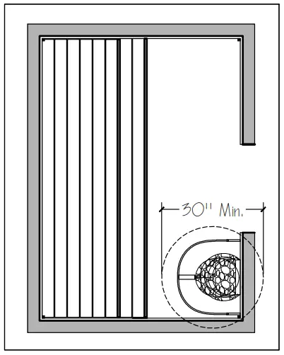
Figure 7: Dimmer Switch Location Elevation View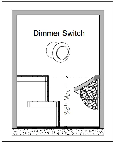
DIMMER Switch Operation
-Tap for On/Off
-Hold for Dim/Brighten
Figure 8: Dimmer Mounting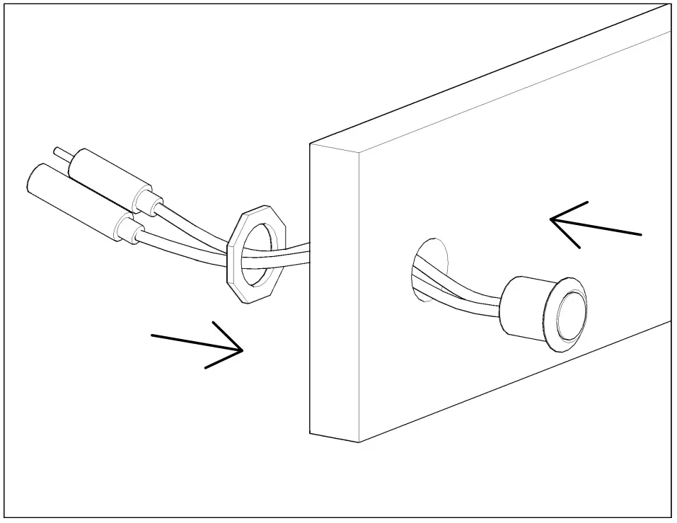
![]() Warning
Warning
The LED should only be mounted using the methods described in this manual. Mounting the LED using methods other than those described in this manual could cause damage to the LED.
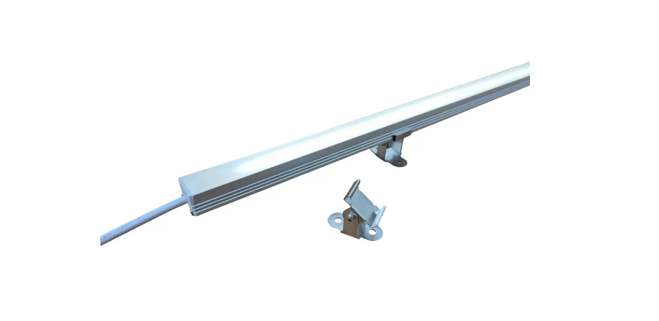
LED Mounting Instructions
- Determine the desired location for the LED. 2. Screw the mounting clips to the mounting surface.
- Attach the LED to the mounting clips by snapping it into place.
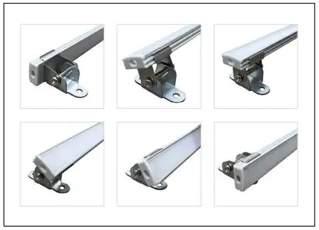
- If using the adjustable clips, tilt the LED bar for the desired light display.
Figure 9: LED Mounting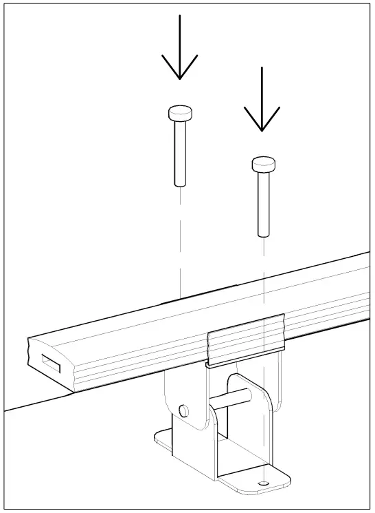
Figure 10: LED Tilting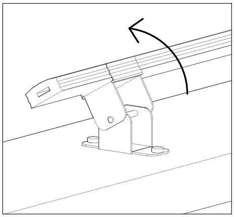
Figure 11: Tilt Variations