![]() IVC1S Series PLC Quick Start
IVC1S Series PLC Quick Start
User Manual
IVC1S Series Programmable Logic Controller
This quick start manual is to offer you a quick guide to the design, installation, connection and maintenance of IVC1S series PLC, convenient for on-site reference. Briefly introduced in this booklet are the hardware specs, features, and usage of IVC1S series PLC, plus the optional parts and FAQ for your reference. For ordering the above user manuals, contact your INVT distributor or sales office.
Introduction
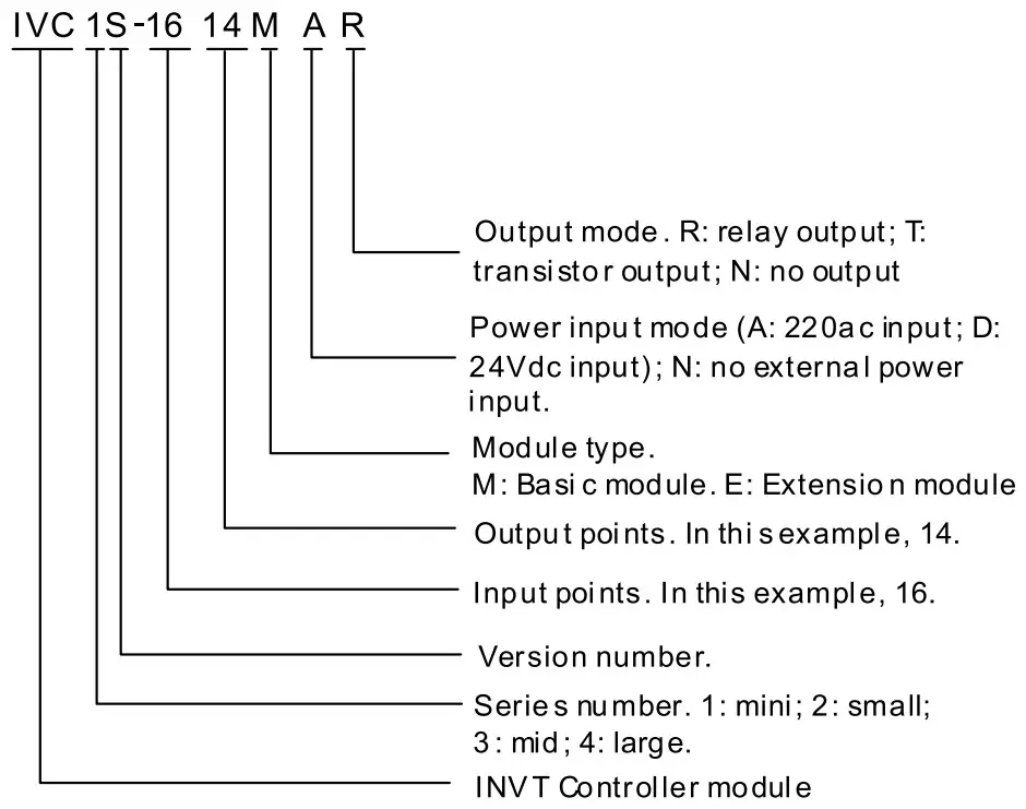
1.1 Model Designation
The model designation is shown in the following figure.
To Customers:
Thank you for choosing our products. To improve the product and provide better service for you, could you please fill in the form after the product has been operated for 1 month, and mail or fax it to our Customer Service Center? We will send you an exquisite souvenir upon receiving the complete Product Quality Feedback Form. Furthermore, if you can give us some advices on improving the product and service quality, you will be awarded a special gift. Thank you very much!
Shenzhen INVT Electric Co., Ltd.
| Customer name | Tele | ||
| Address | Zip code | ||
| Model | Date of use | ||
| Machine SN | |||
| Appearance or structure | |||
| Performance | |||
| Package | |||
| Material | |||
| Quality problem during usage | |||
| Suggestion about improvement | |||
Address: INVT Guangming Technology Building, Songbai Road, Matian, Guangming District, Shenzhen, China
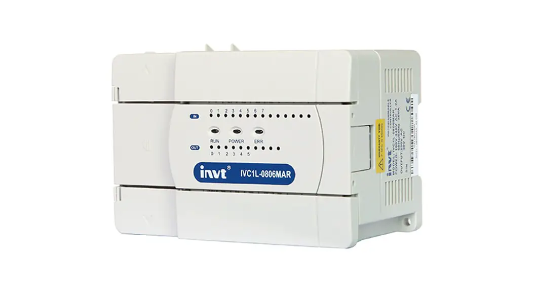
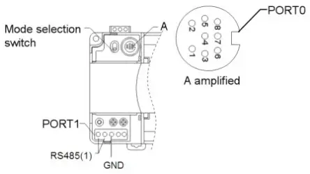
1.2 Outline
The outline of the basic module is shown in the following figure by taking the example of IVC1S-1614MAR.
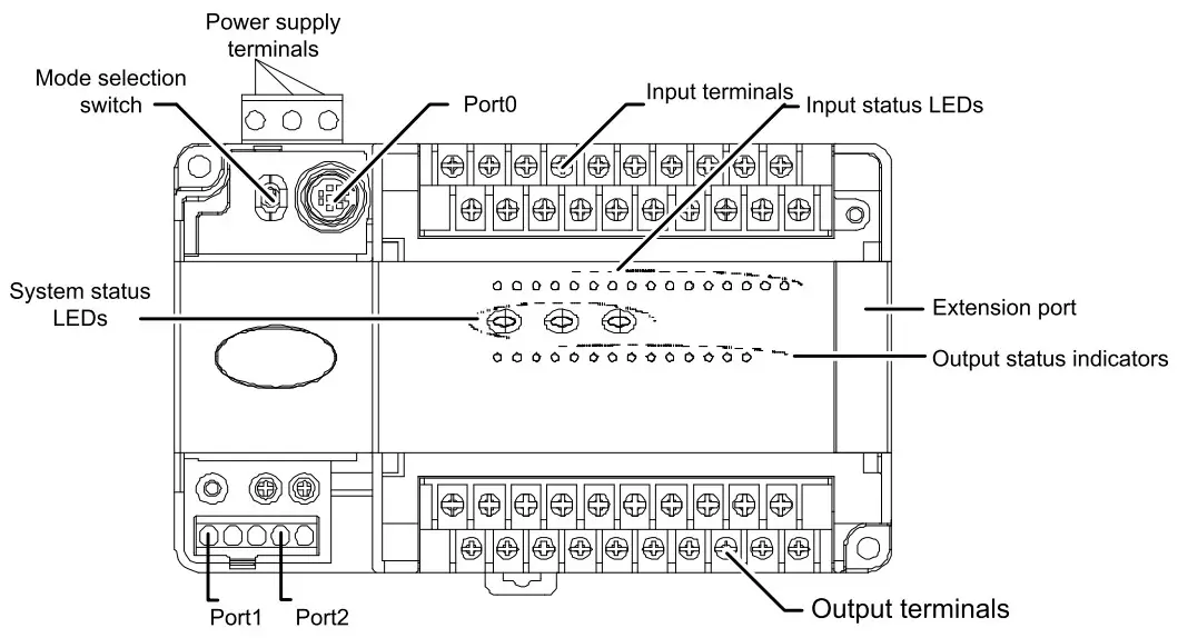
PORTO and PORT1 are communication terminals. PORTO uses RS232 mode with Mini DIN8 socket. PORT1 Has RS485. The mode selection switch has two positions:
ON and OFF.
1.3 Terminal Introduction
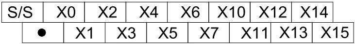
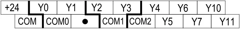
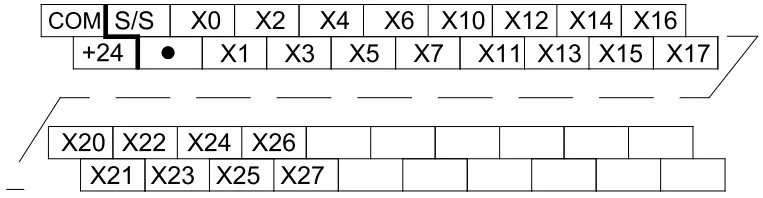
The layouts of terminals of different I/O points are shown below:
1. 14-point, 16-point, 24-point
Input terminal:
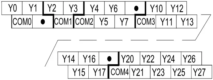
Output terminal:
2. 30-point
Input terminal:

Output terminal: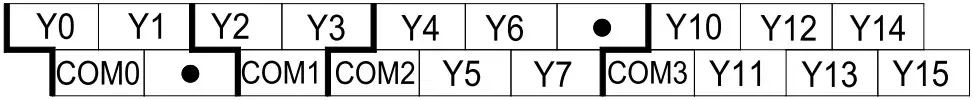
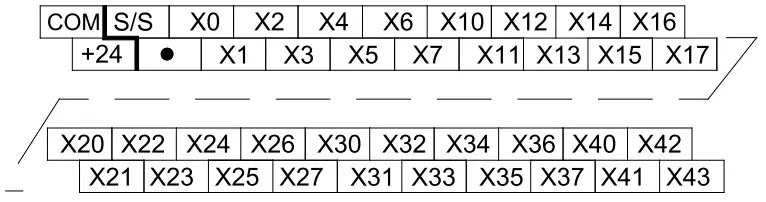
3. 40-point
Input terminal:

Output terminal:

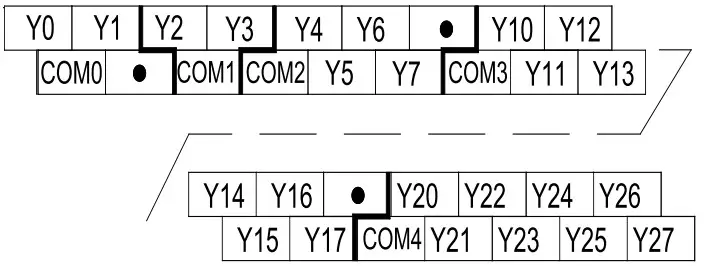
4. 60-point
Input terminal:
Output terminal:
5. 48-point
Input terminal:
Output terminal:
Power Supply
The specification of PLC built-in power and power for extension modules is listed in the following table.
| Item | Unit | Min. | Rated | Max. | Note | |
| Power supply voltage | Vac | 85 | 220 | 264 | Normal startup and operation | |
| Input current | A | / | / | 2. | Input: 90Vac, 100% output | |
| Output current | 5V/GND | mA | / | 600 | / | The total power of outputs 5V/GND and 24V/GND < |
| 24V/GND | mA | / | 250 | / | ||
| 10.4W. Max. output power: 15W (sum of all branches) | ||||||
| 24V/COM | mA | / | 250 | / | ||
Digital Inputs & Outputs
3.1 Input Characteristic And Specification
The input characteristic and specs are shown as follows:
| Item | High-speed input terminals X0—X7 | General input terminal | |
| Input mode | Source mode or sink mode, set through s/s terminal | ||
| Electric parameters | Input voltage | 24Vdc | |
| Input impedance | 4k Ω | 4k Ω | |
| Input ON | External circuit resistance < 400 Ω | ||
| Input OFF | External circuit resistance > 24k Ω | ||
| Filtering function | Digital filter | X0—X7 have digital filtering function. Filtering time: 0, 8, 16, 32 or 64ms (selected through user programme) | |
| Hardware filter | Input terminals other than X0—X7 are of hardware filtering. Filtering time: about 10ms | ||
| High-speed function | X0— X7: high-speed counting, interrupt, and pulse catching X0— X5: up to 10kHz counting frequency The sum of input frequency should be less than 60kHz | ||
| Common terminal | Only one common terminal: COM | ||
The input terminal act as a counter has a limit over the maximum frequency. Any frequency higher than that may result in incorrect counting or abnormal system operation. Make sure that the input terminal arrangement is reasonable and external sensors used are proper.
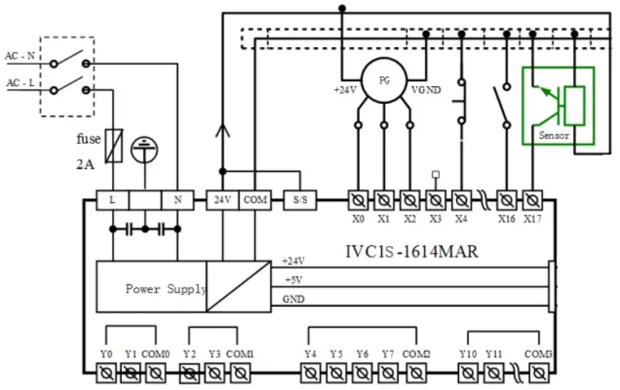
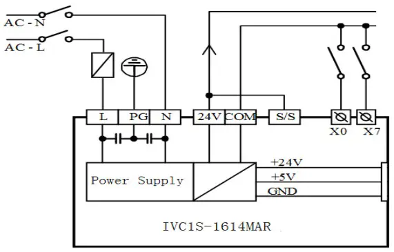
Input connection example
The following diagram shows an example of IVC1S-1614MAR, which realizes simple positioning control. The positioning signals from the PG are input through high speed counting terminals XO and Xt, the limit switch signals that require high-speed response can be input through high-speed terminals X2—X7. Other user signals can be input through any other input terminals.
3.2 Output Characteristic And Specification
The following table shows the relay output and transistor output.
| Item | Relay output | Transistor output |
| Output mode | When output state is ON, the circuit is closed; OFF, open | |
| Common terminal | Divided into multiple groups, each with a common terminal COMn, suitable for control circuits with different potentials. All common terminals are isolated from each other | |
| Voltage | 220Vac; 24Vdc, no polarity requirement | 24Vdc, correct polarity required |
| Current | Accord with output electric specs (see following Table ) | |
| Difference | High driving voltage, large current | Small driving current, high frequency, long lifespan |
| Application | Loads with low action frequency such as intermediate relay, contactor coil, and LEDs | Loads with high frequency and long life, such as control servo amplifier and electromagnet that action frequently |
The electric specs of outputs is shown in the following table.
| Item | Relay output terminal | Transistor output terminal | |
| Switched voltage | Below 250Vac, 30Vdc | 5-24Vdc | |
| Circuit isolation | By Relay | Photo Coupler | |
| Operation indication | Relay output contacts closed, LED on | LED is on when optical coupler is driven | |
| Leakage current of open circuit | / | Less than 0.1mA/30Vdc | |
| Minimum load | 2mA/5Vdc | 5mA (5-24Vdc) | |
| Max. output current | Resistive load | 2A/1 point; 84/4 points, using a COM 84/8 points, using a COM | YO/Y1: 0.3A/1 point. Others: 0.3A/1 point, 0.8A/4 point, 1.24/6 point, 1.64/8 point. Above 8 points, total current increases 0.1A at each point increase |
| Inductive load | 220Vac, 80VA | YO/Y1: 7.2W/24Vdc Others: 12W/24Vdc | |
| Illumination load | 220Vac, 100W | YO/Y1: 0.9W/24Vdc Others: 1.5W/24Vdc | |
| Response time | OFF → ON | 20ms Max | YO/Y1: 10us Others: 0.5ms |
| ON → OFF | 20ms Max | ||
| Y0, Y1 max. output frequency | / | Each channel: 100kHz | |
| Output common terminal | YO/ Y1-COMO; Y2/Y3-COM1. After Y4, Max 8 terminals use one isolated common terminal | ||
| Fuse protection | No | ||
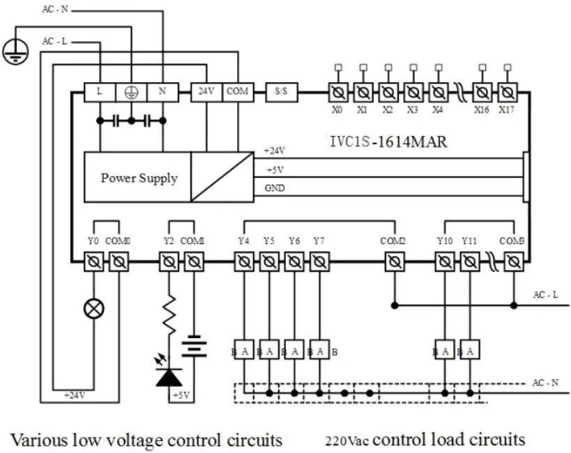
Output connection example
The following diagram shows an example of IVC1S-1614MAR. Different output groups can be connected to different signal circuits with different voltages. Some (like YO-COMO) are connected to the 24Vdc circuit powered by local 24V-COM, some (like Y2-COM1) are connected to the 5Vdc low voltage signal circuit, and others (like Y4 —Y7) are connected to the 220Vac voltage signal circuit.
Communication Port
IVC1S series PLC basic module has three serial asynchronous communication ports: PORTO and PORT1. Supported baud rates:
| 115200 bps | 57600 bps | 38400 bps | 19200 bps |
| 9600 bps | 4800 bps | 2400 bps | 1200 bps |
The mode selection switch determines the communication protocol.
| Pin No. | Name | Description |
| 3 | GND | Ground |
| 4 | RXD | Serial data receiving pin (from RS232 to PLC) |
| 5 | TXD | Serial data transmitting pin (from PLC to RS232) |
| 1, 2, 6, 7, 8 | Reserved | Undefined pin, leave it suspended |
As a terminal dedicated to user programming, PORTO can be converted to programming protocol through the mode selection switch. The relationship between PLC operation status and the protocol used by PORTO is shown in the following table.
| Mode selection switch position | status | PORTO operation protocol |
| ON | Running | Programming protocol, or Modbus protocol, or free-port protocol, or N: N network protocol, as determined by user program and system configuration |
| OFF | Stop | Converted to programming protocol |
PORT1 is ideal for connection with equipment that can communicate (such as inverters). With Modbus protocol or RS485 terminal free protocol, it can control multiple devices through the network. Its terminals are fixed with screws. You can use a shielded twisted-pair as the signal cable to connect communication ports by yourself.
Installation
PLC is applicable to Installation category II, Pollution degree 2.
5.1 Installation Dimensions
| Model | Length | Width | Height | Weight |
| IVC1 S-0806MAR, IVC1 S-0806MAT | 135mm | 90mm | 71.2mm | 440g |
| IVC1S-1006MAR, IVC1S-1006MAT | 440g | |||
| IVC1S-1208MAR, IVC1S-1208MAT | 455g | |||
| IVC1S-1410MAR, IVC1S-1410MAT | 470g | |||
| IVC1S-1614MAR, IVC1S-1614MAT | 150mm | 90mm | 71.2mm | 650g |
| IVC1S-2416MAR, IVC1S-2416MAT | 182mm | 90mm | 71.2mm | 750g |
| IVC1S-3624MAR, IVC1S-3624MAT | 224.5mm | 90mm | 71.2mm | 950g |
| IVC1S-2424MAR, IVC1S-2424MAT | 224.5mm | 90mm | 71.2mm | 950g |
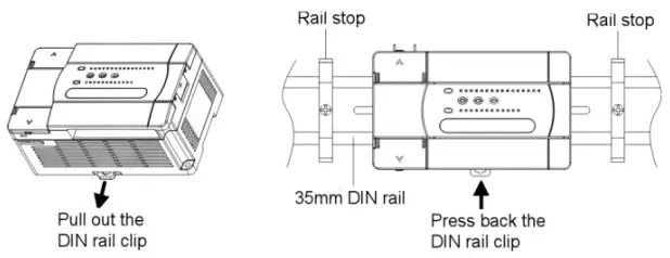
5.2 Installation Method
DIN rail mounting
Generally you can mount the PLC onto a 35mm-wide rail (DIN), as shown in the following figure.
Screw fixing
Fixing the PLC with screws can stand greater shock than DIN rail mounting. Use M3 screws through the mounting holes on PLC enclosure to fix the PLC onto the backboard of the electric cabinet, as shown in the following figure.

5.3. Cable Connection And Specification
Connecting power cable and grounding cable
The connection of AC power and auxiliary power is demonstrated in the following figure.
We suggest you wire a protection circuit at the power supply input terminal. See the figure below.
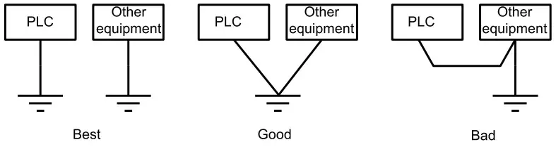
Connect the PLC![]() terminal to the grounding electrode. To ensure reliable grounding cable connection, which makes the equipment safer and protects it from EMI. use AWG12 – 16 cable, and make the cable as short as possible. Use independent grounding. Avoid sharing route with the grounding cable of other equipment (particularly those with strong EMI). See the following figure.
terminal to the grounding electrode. To ensure reliable grounding cable connection, which makes the equipment safer and protects it from EMI. use AWG12 – 16 cable, and make the cable as short as possible. Use independent grounding. Avoid sharing route with the grounding cable of other equipment (particularly those with strong EMI). See the following figure.
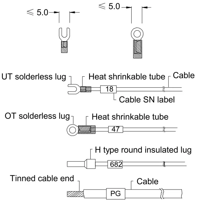
Cable specification
When wiring a PLC, use multi-strand copper wire and ready-made insulated terminals to ensure the quality. The recommended model and the cross-sectional area of the cable are shown in the following table.
| Wire | Cross-sectional area | Recommended model | Cable lug and heat-shrink tube |
| AC power cable (L, N) | 1.0-2.0mm² | AWG12, 18 | H1.5/14 round insulated lug, or tinned cable lug |
| Earth cable ( | 2.0mm2 | AWG12 | H2.0/14 round insulated lug, or tinned cable end |
| Input signal cable (X) | 0.8-1.0mm² | AWG18, 20 | UT1-3 or OT1-3 solderless lug Φ3 or Φ4 heat shrinkable tube |
| Output signal cable (Y) | 0.8-1.0mm² | AWG18, 20 |
Fix the prepared cable head onto the PLC terminals with screws. Fastening torque: 0.5-0.8Nm.
The recommended cable processing-method is shown in the following figure.
Power-on Operation And Maintenance
6.1 Startup
Check the cable connection carefully. Make sure that the PLC is clear of alien objects and the heat dissipation channel is clear.
- Power on the PLC, the PLC POWER indicator should be on.
- Start the Auto Station software on the host and download the compiled user program to the PLC.
- After checking the download program, switch the mode selection switch to the ON position, the RUN indicator should be on. If the ERR indicator is on, the user program or the system is faulty. Loop up in the [V2/IVC1S series PLC Programming Manual and remove the fault.
- Power on the PLC external system to start system debugging.
6.2 Routine Maintenance
Do the following:
- Ensure the PLC a clean environment. Protect it from aliens and dust.
- Keep the ventilation and heat dissipation of PLC in good condition.
- Ensure that the cable connections are reliable and in good condition.
![]() Warning
Warning
- Never connect the transistor output to an AC circuit (like 220Vac). The design of the output circuit must abide by the requirements of electric parameters, and no over-voltage or over-current is allowed.
- Use the relay contacts only when necessary, because the life span of relay contacts depends largely on its action times.
- The relay contacts can support loads smaller than 2A. To support larger loads, use external contacts or mid-relay.
- Note that the relay contact may fail to close when the current is smaller than 5mA.
Notice
- The warranty range is confined to the PLC only.
- Warranty period is 18 months, within which period INVT conducts free maintenance and repairing to the PLC that has any fault or damage under the normal operation conditions.
- The start time of warranty period is the delivery date of the product, of which the product SN is the sole basis of judgment. PLC without a product SN shall be regarded as out of warranty.
- Even within 18 months, maintenance will also be charged in the following situations:
■ Damages incurred to the PLC due to mis-operations, which are not in compliance with the User Manual;
■ Damages incurred to the PLC due to fire, flood, abnormal voltage, etc;
■ Damages incurred to the PLC due to the improper use of PLC functions. - The service fee will be charged according to the actual costs. If there is any contract, the contract prevails.
- Please keep this paper and show this paper to the maintenance unit when the product needs to be repaired.
- If you have any question, please contact the distributor or our company directly.
Shenzhen INVT Electric Co., Ltd.
Address: INVT Guangming Technology Building, Songbai Road,
Matian, Guangming District, Shenzhen, China
Website: www.invt.com
All rights reserved.
The contents in this document are subject to change without notice.
Version: V1.0 202212


