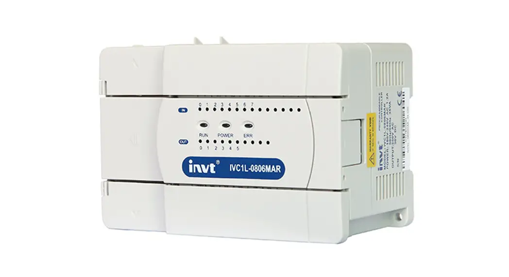
![]() IVIC1L-1616MAR-T Micro Programmable Logic Controller
IVIC1L-1616MAR-T Micro Programmable Logic Controller
User Guide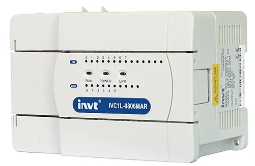 Version: V1.0 202212
IVIC1L-1616MAR-T Micro Programmable Logic Controller
Quick Reference Manual of IVC1L-1616MAR-T with 2PT PLC
This quick start manual is to offer you a quick guide to the design, installation, connection and maintenance of IVC1L-1616MAR-T series PLC, convenient for on-site reference. Briefly introduced in this booklet are the hardware specs, features, and usage of IVC1L-1616MAR-T PLC, plus the optional parts and FAQ for your reference. For ordering the above user manuals, contact your INVT distributor or sales office. You can also visit http://www.invt-control.com to download PLC-related technical information or give feedback on PLC-related issues.
Introduction
1.1 Model Designation
The model designation is shown in the following figure. 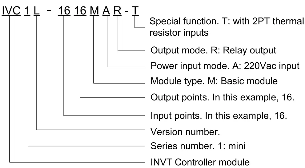
To Customers: Thank you for choosing our products. To improve the product and provide better service for you, could you please fill in the form after the product has been operated for 1 month, and mail or fax it to our Customer Service Center? We will send you an exquisite souvenir upon receiving the complete Product Quality Feedback Form. Furthermore, if you can give us some advices on improving the product and service quality, you will be awarded a special gift. Thank you very much!
Shenzhen INVT Electric Co., Ltd.
Product Quality Feedback Form
| Customer name | Phone | ||
| Address | Postal | Code | |
| Model | Date of use | ||
| Machine SN | |||
| Appearance or structure | |||
| Performance | |||
| Package | |||
| Material | |||
| Quality problem during usage | |||
| Suggestion about improvement | |||
Address: INVT Guangming Technology Building, Songbai Road, Matian, Guangming District, Shenzhen, China Tel: +86 23535967
1.2 Outline
The outline of the basic module is shown in the following figure by taking the example of IVC1L-1616MAR-T.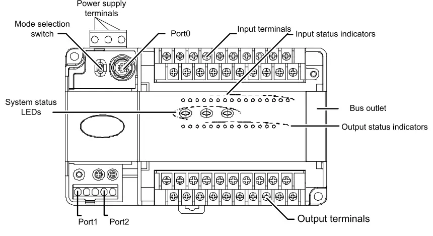 PORTO and PORT1 PORT2 are communication terminals. PORTO uses RS232 mode with Mini DIN8 socket. PORT1 and PORT2 have double RS485. The busbar socket is for connecting the extension module. The mode selection switch has three positions: ON, TM and OFF.
1.3 Terminal Introduction
1. The layouts of terminals are shown as follows: Input terminals:  Input terminal definition table
| No. | Sign | Description | No. | Sign | Description |
| 1 | S/S | Input source/sink mode selection terminal | 14 | X1 | Digital signal X1 input terminal |
| 2 | XO | Digital signal XO input terminal | 1 c I”‘ | n ‘ | Digital signal X3 input terminal |
| 3 | X2 | Digital signal X2 input terminal | 16 | c X’ | Digital signal X5 input terminal |
| 4 | X4 | Digital signal X4 input terminal | 17 ‘ ‘ | y7 ” | Digital signal X7 input terminal |
| 5 | X6 | Digital signal X6 input terminal | 18 | X11 | Digital signal X11 input terminal |
| 6 | X10 | Digital signal X10 input terminal | 19 | X13 | Digital signal X13 input terminal |
| 7 | X12 | Digital signal X12 input terminal | 20 | X15 | Digital signal X15 input terminal |
| 8 | X14 | Digital signal X14 input terminal | 21 | X17 | Digital signal X17 input terminal |
| 9 | X16 | Digital signal X16 input terminal | 22 | FG | RTD cable shield ground |
| 10 | 11 | Positive RTD auxiliary current of CH1 | 23 | R1+ | Positive thermal-resistor sisnal iniut of CH1 |
| 11 | 11 | Negative RTD auxiliary current of CH1 | 24 | R1 | Negative thermal-resistor sisnal ineut of CH1 |
| 12 | 12+ | Positive RTD auxiliary current of CH2 | 25 | R2+ | Positive thermal-resistor sisnal iniut of CH2 |
| 13 | 12— | Negative RTD auxiliary current of CH2 | 26 | R2— | Negative thermal-resistor signal input of CH2 |
Output terminals: 
| No. | Sign | Description | No. | Sign | Description |
| 1 | +24 | Positive pole of output power supply 24V | 14 | COM | Negative pole of output power supply 24V |
| 2 | YO | Control output terminal | 15 | COMO | Control output common terminal |
| 3 | Y1 | Control output terminal | 16 | Empty | |
| 4 | Y2 | Control output terminal | 17 | COM1 | Common terminal of control output terminal |
| 5 | Y3 | Control output terminal | 18 | COM2 | Common terminal of control output terminal |
| 6 | Y4 | Control output terminal | 19 | Y5 | Control output terminal |
| 7 | Y6 | Control output terminal | 20 | Y7 | Control output terminal |
| 8 | • | Empty | 21 | COM3 | Common terminal of control output terminal |
| 9 | Y10 | Control output terminal | 22 | Yll | Control output terminal |
| 10 | Y12 | Control output terminal | 23 | Y13 | Control output terminal |
| 11 | Y14 | Control output terminal | 24 | Y15 | Control output terminal |
| 12 | Y16 | Control output terminal | 25 | Y17 | Control output terminal |
| 13 | • | Empty | 26 | • | Empty |
Power supply specifications
The specification of PLC built-in power and power for extension modules is listed in the following table.
| Item | Unit | Min. | Typical value | Max. | Note | |
| Power supply voltage | Vac | 85 | 220 | 264 | Normal startup and operation | |
| Input current | A | / | / | 2. | Input: 90Vac, 100% output | |
| Rated output current | 5V/GND | mA | / | 900 | / | The total power of outputs 5V/GND and 24V/GND 10.4W. Max. output power: 24.8W (sum of all branches) |
| 24V/GND | mA | / | 300 | / | ||
| +-15V/AGND | mA | / | 200 | |||
| 24V/COM | mA | / | 600 | / | ||
Digital Inputs & Outputs
3.1 Input Characteristic And Specification
The input characteristic and specs are shown as follows:
| Item | High-speed input terminals X0—X7 | General input terminal | |
| Input mode | Source mode or sink mode, set through s/s terminal | ||
| Electric parameters | Input voltage | 24Vdc | |
| Input resistance | 4k0 | 4.3k0 | |
| Input ON | External circuit resistance < 4000 | External circuit resistance < 4000 | |
| Input OFF | External circuit resistance > 24k0 | External circuit resistance > 24k0 | |
| Filtering function | Digital filter | X0—X7 have digital fi time: 0, 8, 16, 32 or 64ms programme) | tering function. Filtering (selected through user |
| Hardware filter | Input terminals other than X0—X7 are of hardware filtering. Filtering time: about 10ms | ||
| High-speed function | X0—X7: high-speed counting, interrupt, and pulse catching XO and X1: up to 50kHz counting frequency X2—X5: up to 10kHz counting frequency The sum of input frequency should be less than 60kHz | ||
| Common terminal | Only one common terminal: COM | ||
The input terminal act as a counter has a limit over the maximum frequency. Any frequency higher than that may result in incorrect counting or abnormal system operation. Make sure that the input terminal arrangement is reasonable and external sensors used are proper.
The PLC provides an S/S terminal for selecting signal input mode among source mode and sink mode. Connecting the S/S terminal to the +24 terminal, i.e. set the input mode to the sink mode, enables a connection with the NPN sensor. 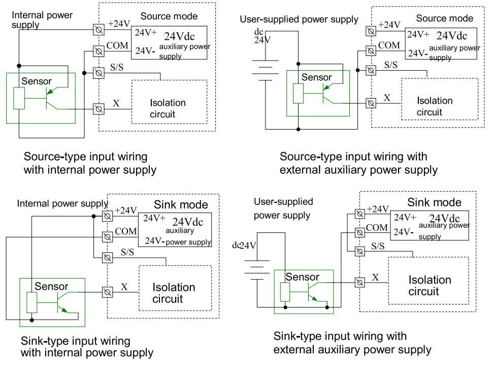 Input connection example
The following diagram shows an example of IVC1L-1616MAR-T in connection with an IVC1-0808ENR, which realizes simple positioning control. The positioning signals from the PG are input through high speed counting terminals XO and X1, the limit switch signals that require high-speed response can be input through high-speed terminals X2—X7. Other user signals can be input through any other input terminals. 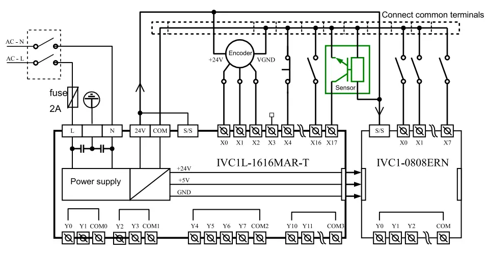
3.2 Output Characteristic And Specification
The electric specs of outputs is shown in the following table.
| Item | Relay output | |
| Switched voltage | Below 250Vac, 30Vdc | |
| Circuit isolation | By Relay | |
| Operation indication | Relay output contacts closed, LED on | |
| Leakage current of open circuit | / | |
| Minimum load | 2mA/5Vdc | |
| Max. output current | Resistive load | 2A/1 point; 8A/4 points, using a COM 8A/8 points, using a COM |
| Inductive load | 220Vac, 80VA | |
| Illumination load | 220Vac, 100W | |
| Response time | OFF—›ON | 20ms Max |
| ON—*OFF | 20ms Max | |
| Y0, Y1 max. output frequency | / | |
| Y2, Y3 max. output frequency | / | |
| Output common terminal | YO/ Y1-COMO; Y2/Y3-COM1. After Y4, Max 8 terminals use one isolated common terminal | |
| Fuse protection | None | |
Output connection example
The following diagram shows an example of IVC1L-1616MAR-T in connection with an IVC1-0808ENR. Some (like Y0-COMO) are connected to the 24Vdc circuit powered by local 24V-COM, some (like Y2-COM1) are connected to the 5Vdc low voltage signal circuit, and others (like Y4—Y7) are connected to the 220Vac voltage signal circuit. Different output groups can be connected to different signal circuits with different voltages.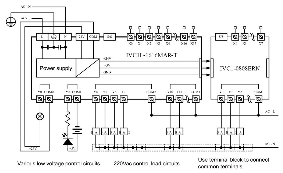
3.3 Thermistor Characteristic And Specification
Performance Specification
| Item | Specification | |||
| Degrees Celsius (°C) | I Degrees Fahrenheit (°F) ‘ | |||
| Input signal. | Termistor type: Pt100, Cu100, Cu50 Number of channels: 2 | |||
| Converting speed | (15±2%) ms x 4 channels (The conversion is not performed for unused channels.) | |||
| Rated temperature range | Pt100 | —150°C—+600°C | Pt100 | —238°F—+1112°F |
| Cu100 | —30°C—+120°C | Cu100 | —22°F—+248°F | |
| Cu50 | —30°C—+120°C | Cu50 | —22°F—+248°F | |
| Digital output | The temperature value is stored in 16-bit binary complement code. | |||
| Pt100 | —1500—+6000 | Pt100 | —2380—+11120 | |
| Cu100 | —300—+1200 | Cu100 | —220—+2480 | |
| Cu50 | —300—+1200 | Cu50 | —220—+2480 | |
| Item | Specification | |||
| Degrees Celsius (°C) | Degrees Fahrenheit (°F) | |||
| Lowest resolution | Pt100 | 0.2°C | Pt100 | 0.36°F |
| Cu100 | 0.2°C | Cu100 | 0.36°F | |
| Cu50 | 0.2°C | Cu50 | 0.36°F | |
| Precision | ±1% of the full range | |||
| Isolation | Analog circuits are isolated from digital circuits by using photoelectric couplers. Analog channels are not isolated from each other. | |||
The following figure shows the terminal wiring: 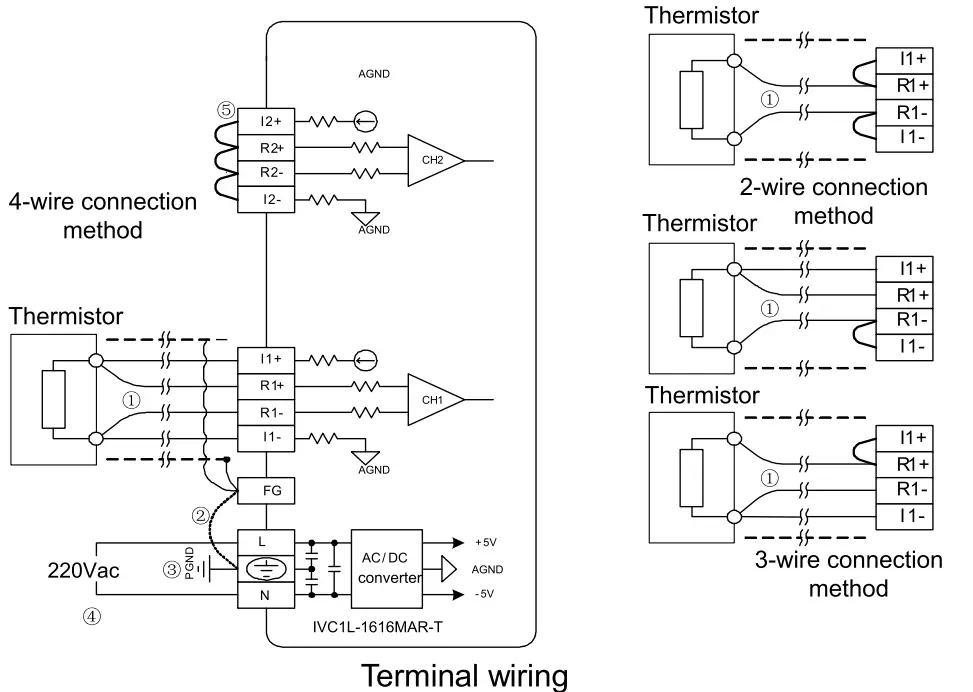 The labels 0 to 0 in the above figure indicate the connection that you need to pay special attention to.
- It is recommended that you connect the thermistor signals by using a shielded twisted-pair cable, and keep the cable away from power cables or other cables that may cause electrical interference. The connection of a thermistor is described as follows:
For thermistor sensors of the Pt100, Cu100, and Cu50 types, you can use the 2-wire, 3-wire, and 4-wire connection methods. Among them, the precision of the 4-wire connection method is the highest, that of the 3-wire connection method is the second highest, and that of the 2-wire connection method is the lowest. If the length of the wire is longer than 10 m, it is recommended that you use the 4-wire connection method to eliminate the resistance error caused by the wire.
To reduce measurement errors and prevent noise interference, it is recommended that you use connection cables that are shorter than 100 m. - If too much electrical interference is caused, connect the shielding ground to the ground terminal PG of the module.
- Ground the ground terminal PG of the module properly.
- Use 220Vac power supply. O. Short-circuit the positive and negative terminals that do not use a channel to prevent the detection of error data on the channel.
SD unit configuration
| Address No. | Name | RIW attribute | Note |
| SD172 | Sampling average of CH1 | R | Default value: 0 |
| SD173 | Sampling times of CH1 | RW | 1-1000, Default value: 8 |
| SD174 | Sampling average of CH2 | R | Default value: 0 |
| SD175 | Sampling times of CH2 | RW | 1-1000, Default value: 8 |
| SD178 | Mode selection for CH1 (8 LSBs) Mode selection for CH2 (8 MSBs) | RW | 0: Disable 1:PT100 (-1500-6000, degrees Celsius) 2:PT100 (-2380-11120, degrees Fahrenheit) 3:Cu100 (-300-1200, degrees Celsius) 4:Cu100 (-220-2480, degrees Fahrenheit) 5:Cu50 (-300-1200, degrees Celsius) 6:Cu50 (-220-2480, degrees Fahrenheit) |
Setting example:
In order to configure the PT100 for both CH1 and CH2, output the value in degrees Celsius, and set the points of average value to 4, you need to set the 8 leaset significant bits(LSBs) of SD178 to Ox01 and the 8 most significant bits(MSBs) of SD178 to Ox01, i.e. set the SD178 to Ox0101(hexadecimal). Then set the SD173 and SD175 to 4. The values of SD172 and SD174 are the average temperatures in Celsius degree of the four samplings detected by the CH1 PT100 and CH2 PT100, respectively.
Communication Port
IVC1L-1616MAR-T basic module has three serial asynchronous communication ports: PORTO, PORT1, and PORT2. Supported baud rates: 115200, 57600, 38400, 19200, 9600, 4800, 2400, 1200bps. The mode selection switch determines the communication protocol of PORTO.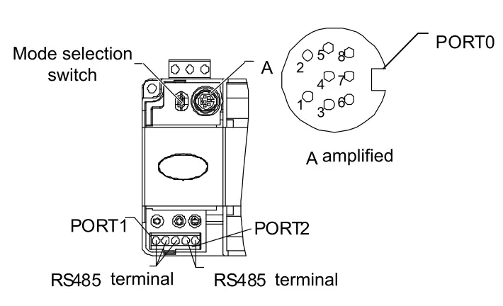
| Pin No. | Name | Description |
| 3 | GND | Ground |
| 4 | RXD | Serial data receiving pin (from RS232 to PLC) |
| 5 | TX D | Serial data transmitting pin (from PLC to RS 232) |
| 1, 2, 6, 7,8 | Reserves | Undefined pin, leave it suspended |
As a terminal dedicated to user programming, PORTO can be converted to programming protocol through the mode selection switch. The relationship between PLC operation status and the protocol used by PORTO is shown in the following table.
| Mode selection switch position | Status | PORTO operation protocol |
| ON- | Run | Programming protocol, or Modbus protocol,or free-port protocol, or N: N network protocol, as determined by user program and system configuration |
| ON→TM | Running | Converted to programming protocol |
| OFF →TM | Stop | |
| OFF | Stop | If the system configuration of user program is free-port protocol, it converts to programming protocol automatically after stop; or system protocol keeps unchanged |
PORT1. PORT2 are ideal for connection with equipment that can communicate (such as inverters). With Modbus protocol or RS485 terminal free protocol, it can control multiple devices through the network. Its terminals are fixed with screws. You can use a shielded twisted-pair as the signal cable to connect communication ports by yourself.
Installation
PLC is applicable to Installation category II, Pollution degree 2.
5.1 Installation Dimensions
| Model | Length | Width | Height | Net weight |
| IVCAL-1616MAR-T | 182mm | 90mm | 71.2mm | 750g |
5.2 Installation Method
DIN rail installation
Generally you can install the PLC onto a 35mm-wide rail (DIN), as shown in the following figure. 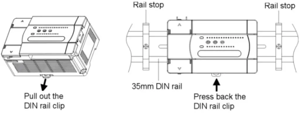
The detailed procedure is as follows:
- Fix the DIN rail onto the installation backplane;
- Pull out the DIN rail clip from the bottom of the module;
- Mount the module to the DIN.
- Press back the DIN rail clip to lock the module.
- Fix the two ends of the module with the rail stops to avoid sliding.
This procedure can be used to install the DIN rail for all other IVC1L-1616MAR-T PLCs.
Screw fixing
Fixing the PLC with screws can stand greater shock than DIN rail mounting.
Use M3 screws through the mounting holes on PLC enclosure to fix the PLC onto the backboard of the electric cabinet, as shown in the following figure. 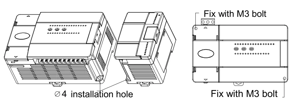
5.3 Cable Connection and Specification
Connect power cable and grounding cable. We suggest you wire a protection circuit at the power supply input terminal. The following figure shows shows the connection of the AC and auxiliary power supplies.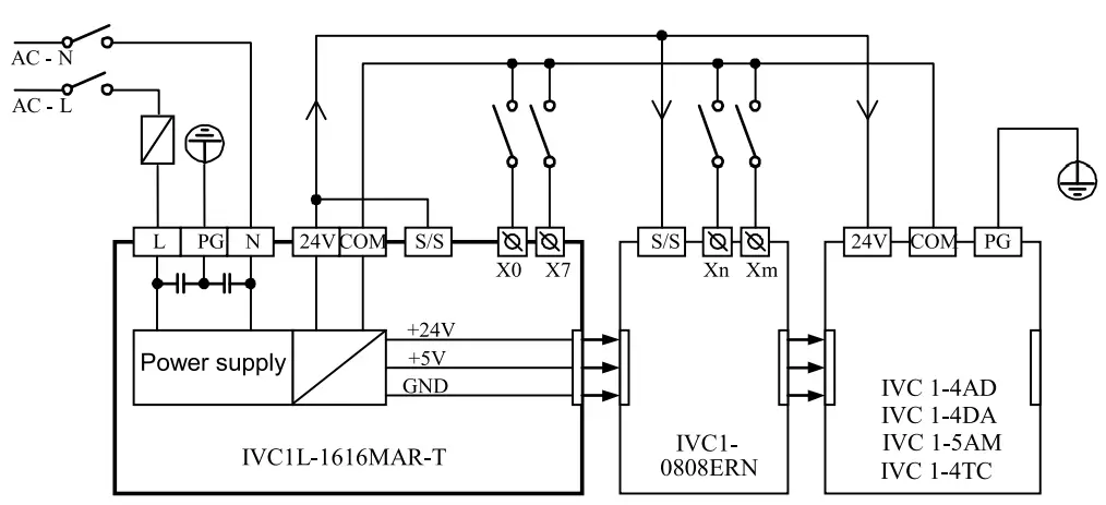 The anti-electromagnetic interference capability of the PLCs can be improved by configuring reliable grounding cables. When installing a PLC, connect the power supply terminal
 ![]() to the ground. It is recommended that you use connection wires of AWG12 to AWG16 and try to shorten the wires, and that you configure independent grounding and keep the grounding cables away from those of other devices (especially those generating strong interference), as shown in the following figure.
to the ground. It is recommended that you use connection wires of AWG12 to AWG16 and try to shorten the wires, and that you configure independent grounding and keep the grounding cables away from those of other devices (especially those generating strong interference), as shown in the following figure.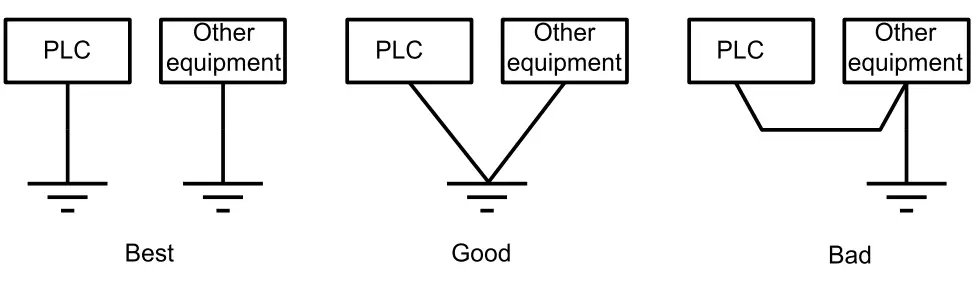
Cable specification
When wiring a PLC, use multi-strand copper wire and ready-made insulated terminals to ensure the quality. The recommended model and the cross-sectional area of the cable are shown in the following table.
| Cable | Cross-sectional area | Recommended model | Cable lug and heat-shrink tube |
| AC power cable (L, N) | 1.0-2.0mm2 | AWG12, 18 | H1.5/14 round insulated lug, or tinned cable lug |
| Earth cable (e) | 2.0mm2 | AWG12 | H2.0114 round insulated lug, or tinned cable lug |
| Input signal cable (X) | 0.8-1.0mm2 | AWG18, 20 | UT1-3 or OT1-3 solderless lug 1)3 or c1314 heat shrinkable tube |
| Output signal cable (Y) | 0.8-1.0mm2 | AWG18, 20 |
Fix the prepared cable head onto the PLC terminals with screws. Fastening torque: 0.5-0.8Nm.
The recommended cable processing-method is shown in the following figure.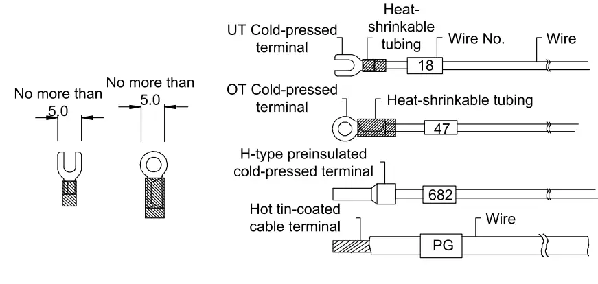
Power-on Operation And Maintenance
6.1 Startup
Check the cable connection carefully. Make sure that the PLC is clear of alien objects and the heat dissipation channel is clear.
- Power on the PLC, the PLC POWER indicator should be on.
- Start the AutoStation software on the host and download the compiled user program to the PLC.
- After checking the download program, switch the mode selection switch to the ON position, the RUN indicator should be on. If the ERR indicator is on, the user program or the system is faulty. Loop up in the IVC series PLC Programming Manual and remove the fault.
- Power on the PLC external system to start system debugging.
6.2 Routine Maintenance
Do the following:
- Ensure the PLC a clean environment. Protect it from aliens and dust.
- Keep the ventilation and heat dissipation of PLC in good condition.
- Ensure that the cable connections are reliable and in good condition.
![]() Warning
Warning
- Use the relay contacts only when necessary, because the life span of
Notice
- The warranty range is confined to the PLC only.
- Warranty period is 18 months, within which period INVT conducts free maintenance and repairing to the PLC that has any fault or damage under the normal operation conditions.
- The start time of warranty period is the delivery date of the product, of which the product SN is the sole basis of judgment. PLC without a product SN shall be regarded as out of warranty.
- Even within 18 months, maintenance will also be charged in the following situations:
Damages incurred to the PLC due to mis-operations, which are not in compliance with the User Manual;
Damages incurred to the PLC due to fire, flood, abnormal voltage, etc;
Damages incurred to the PLC due to the improper use of PLC functions. - The service fee will be charged according to the actual costs. If there is any contract, the contract prevails.
- Please keep this paper and show this paper to the maintenance unit when the product needs to be repaired.
- If you have any question, please contact the distributor or our company directly.
![]() Shenzhen INVT Electric Co., Ltd.
Shenzhen INVT Electric Co., Ltd.
Address: INVT Guangming Technology Building, Songbai Road, Matian,
Guangming District, Shenzhen, China
Website: www.invt.com
All rights reserved. The contents in this document are subject to change without notice.


