
HUBBLE AM-5 5.12kWh 51.2V Battery Solar Pumps

INSTALLATION INSTRUCTION
- It is important that you read this manual before attempting the installation of your battery.
- Please take note of certain steps to ensure correct inverter compatibility.
- Please visit www.hubblelithium.co.za or the latest version of this manual.
WARNING:
- Working with high-voltage systems is dangerous. Do not attempt to modify your inverter and battery setup unless you are certain you understand the risk. Speak to a qualified electrician if you are unsure.
Product Description
![]()
- SMART: Every module is equipped with an independent BMS system.
- EASY: INSTALLATION Just plug & play.
- SAFE: Safe lithium iron phosphate battery cell.
- CERTIFIED: CE IEC UN38.3 MSDS.
- MODULAR: Modular expansion
- LONGER LIFETIME: 6000 cycles, 15 years of design life.
TECHNICAL SPECIFICATIONS
| TECHNICAL SPECIFICATIONS | |
| Model | AM-5 |
| Battery Type | LiFePO4 (LFP) |
| Nominal Voltage (V) | 51.2V |
| Nominal Energy (KWH) | 5.12KWH |
| Design Capacity | 100AH |
| Design Years | 15 Years |
| PRODUCT SIZE | |
| Size | 600*510*173mm |
| Weight | 51kg |
| TECHNICAL PARAMETER | |
| Cycle Life | ≥6000 80% DOD |
| Operating Voltage Range | 40V-58.4V |
| Charging Voltage | DC 58.4V |
| Charge/Discharge Current(A) | Same Port 100A |
| internal Resistance | ≥30mΩ |
| BMS PARAMETERS | |
| Self-Consumption | ≥2W |
| Rated Voltage | 51.2V |
| Balance Current | 30-65(MA) |
| Communication Method | CAN/RS485/RS232 |
| Intelligent Current Limiter | 20A |
| AMBIENT TEMPERATURE | |
| Operating Temperature | -10C ~ 50C |
| Storage Temperature | 10 C ~ 50C |
| Humidity | 15% ~ 75% |
- Lithium battery systems are widely used in residential energy storage systems, such as solar energy storage systems and UPS.
- The power wall LiFeP04 battery pack adopts the international advanced lithium iron phosphate battery application technology and BMS control technology.
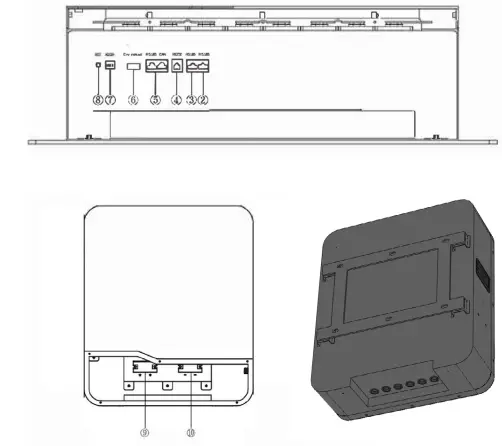
INTERFACE & SIZE
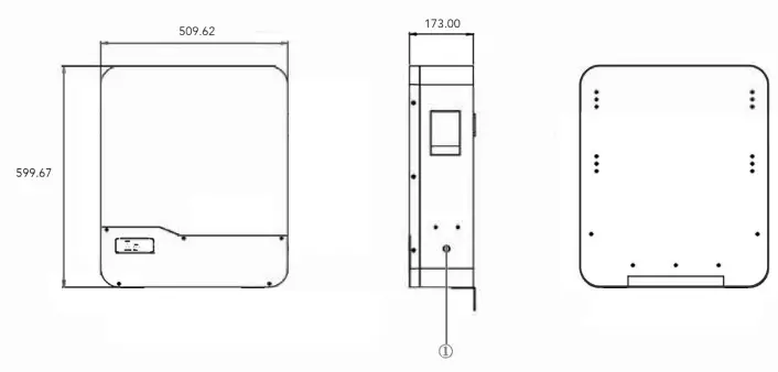
- POWER SWITCH
- BATTERY LINK
- BATTERY LINK
- RS232
- CAN/RS485 EXTERNAL COMMUNIATION
- DRY CONTACT
- ADD
- RST
- BATTERY +
- BATTERY –

PARALLEL
CONNECTION OF BATTERIES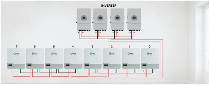
SOLUTION DIAGRAM: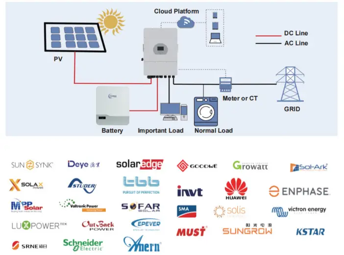
installation
notes
- As shown in the figure below, press the mounting structure on the wall surface, use a marker to draw the installation positioning hole of the fixed pendant, remove from wall and drill the holes.

- As shown in the figure below, fix the attached six expansion bolts in the opening of the mounting structure, and tighten the nuts on the bolts.

- Lift up the AM-5 battery carefully and hook it into position securely onto the wall mount bracket.


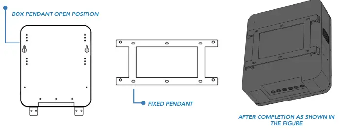
TABLE 1 LED WORKING STATUS INDICATION
| STATUS | NORMAL / ALARM / PROTECTION | RUN
| ALM
| SOC INDICATION LEDS
| REMARK | |||
 | | | | | ||||
| POWER OFF | Dormancy | OFF | OFF | OFF | OFF | OFF | OFF | All off |
| STANDBY | Normal | Fash 1 | OFF | According to the electricity instruction | Standby state | |||
| Alarm | Flash 1 | Flash 3 | Cell low voltage | |||||
|
CHARGE | Normal | Lighting | OFF | According to the electricity instruction (Power level indicates maximum LED flash 2) | Alarm when overvoltage light is off | |||
| Alarm | Lighting | Flash 3 | ||||||
| Overcharge Protection | Lighting | OFF | Lighting | Lighting | Lighting | Lighting | If there is no charging the LED light is in standby state | |
| Temperature Over-current Protection | OFF | Lighting | OFF | OFF | OFF | OFF | Stop charging | |
|
DISCHARGE | Normal | Flash 3 | OFF | According to the electricity instruction. | ||||
| Alarm | Flash 3 | Flash 3 | ||||||
| Undervoltage protection | OFF | OFF | OFF | OFF | OFF | OFF | Stop discharge | |
| Temperature Overcurrent Short-circuit Reverse connection Failure protection |
OFF |
Lighting |
OFF |
OFF |
OFF |
OFF |
Stop discharge | |
| FAIL | OFF | Lighting | OFF | OFF | OFF | OFF | Stop charging and discharging. | |

TABLE 2 CAPACITY INDICATION INSTRUCTIONS
| STATE | CHARGE | DISCHARGE | |||||||
| Capacity Indicator Light | L4 | L3 | L2 | L1 | L4 | L3 | L2 | L1 | |
|
Battery Power (%) | 0 ~ 25% | OFF | OFF | OFF | Flash 2 | OFF | OFF | OFF | Lighting |
| 25 ~ 50% | OFF | OFF | Flash 2 | Lighting | OFF | OFF | Lighting | Lighting | |
| 50 ~ 75% | OFF | Flash 2 | Lighting | Lighting | OFF | Lighting | Lighting | Lighting | |
| 75 ~ 100% | Flash 2 | Lighting | Lighting | Lighting | Lighting | Lighting | Lighting | Lighting | |
TABLE 3 LED FLASH INSTRUCTIONS
| FLASH MODE | ON | OFF |
| FLASH 1 | 0.25 S | 3.75 S |
| FLASH 2 | 0.5 S | O.5 S |
| FLASH 3 | 0.5 S | 1.5 S |
Note: can enable or prohibit LED indicator light alarm through the upper machine, the factory default is enabled.
table 4 dual switch position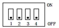
| ADDRESS | CODES THE SWITCH POSITION | |||
| #1 | #2 | #3 | #4 | |
| 1 | OFF | OFF | OFF | OFF |
| 2 | ON | OFF | OFF | OFF |
| 3 | OFF | ON | OFF | OFF |
| 4 | ON | ON | OFF | OFF |
| 5 | OFF | OFF | ON | OFF |
| 6 | ON | OFF | ON | OFF |
| 7 | OFF | ON | ON | OFF |
| 8 | ON | ON | ON | OFF |
| 9 | OFF | OFF | OFF | ON |
| 10 | ON | OFF | OFF | ON |
| 11 | OFF | ON | OFF | ON |
| 12 | ON | ON | OFF | ON |
| 13 | OFF | OFF | ON | ON |
| 14 | ON | OFF | ON | ON |
| 15 | OFF | ON | ON | ON |
| 16 | ON | ON | ON | ON |
interface
definition
DIAGRAM OF THE COMMUNICATION INTERFACE
RS232 communication port definition: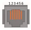
| INTERFACE | DEFINED DECLARATION | |
|
RJ12, RS232 pin layout | PIN 1 | NC (empty) |
| PIN 2 | NC (empty) | |
| PIN 3 | TX protection board sends data (computer receiving data foot) | |
| PIN 4 | RX protection board receives data (computer sends data) | |
| PIN 5 | Ground signal ground | |
| PIN 6 | NC (empty) | |
RS 485-1 / CAN COMMUNICATION INTERFACE DEFINITION: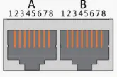
| INTERFACE | DEFINED DECLARATION | DEFINED DECLARATION | ||||
|
X1 Communication port definition |
RJ45 CAN pin layout | PIN 1 | CANL |
RJ45, RS485 pin layout | PIN 1 | RS485-B1 |
| PIN 2 | CGND | PIN 2 | RS485-A1 | |||
| PIN 3 | NC (empty) | PIN 3 | RS485-GND | |||
| PIN 4 | CANH | PIN 4 | RS485-B1 | |||
| PIN 5 | CANL | PIN 5 | RS485-A1 | |||
| PIN 6 | NC (empty) | PIN 6 | RS485-GND | |||
| PIN 7 | CGND | PIN 7 | NC (empty) | |||
| PIN 8 | CANH | PIN 8 | NC (empty) | |||
RS485-2 COMMUNICATION INTERFACE DEFINITION:
| INTERFACE | DEFINED DECLARATION | DEFINED DECLARATION | ||||
|
Battery link ports |
A part RS-485-2 Interface | PIN 1 | RS485-B2 |
B part RS-485-2 Interface | PIN 1 | RS485-B2 |
| PIN 2 | RS485-A2 | PIN 2 | RS485-A2 | |||
| PIN 3 | RS485-GND | PIN 3 | RS485-GND | |||
| PIN 4 | NC (empty) | PIN 4 | NC (empty) | |||
| PIN 5 | NC (empty) | PIN 5 | NC (empty) | |||
| PIN 6 | RS485-GND | PIN 6 | RS485-GND | |||
| PIN 7 | RS485-A2 | PIN 7 | RS485-A2 | |||
| PIN 8 | RS485-B2 | PIN 8 | RS485-B2 | |||
DRY CONTACT DESCRIPTION

This BMS can provide one channel of dry contact signal, all dry contact signals are passive switch-es, regardless of polarity.
| KRY 1 (2P terminal) | ||
| BMS STATE | DESCRIPTION | REMARK |
| Normal Operation | 1/2 pin is disconnected | |
| BMS Alarm | 1/2 pin is connected | Output when SOC alarm, under voltage and over voltage alarm and BMS protection state, such as under voltage protection, over voltage protection or short circuit protection; |
- When the BMS is in sleep state, press the button for more than 1 S, the protection board is activated.
- When the BMS is in operating state, pressing the button more than 3 seconds and less than
- 6 seconds, then the BMS will enter sleep state.When the BMS is in working state, the protection board will reset when the button is pressed for more than 6S.
BUZZER ACTION DESCRIPTION
- In the case of short-circuit protection, the buzzer beeps every 2 seconds. If a short circuit is detected 3 times in a row then he short-circuit protection is locked, the buzzer will no longer beep. Disconnect the battery and wait a few minutes to switch it back on. It might take up to 5 minutes to redetect a clear condition and then the BMS will re enable.
interface
FUNCTIONS
WARNING
Interfacing or plugging in any 3rd party or non approved Hubble products or periphirals into the RS232 (serial) or RS485 (Battery Link) ports, can cause damage to the BMS and cause the BMS to malfunction. This may also result in damaging the internal cells. Plugging in non approved Hubble products into these ports can immediately void your warranty.
DESCRIPTION OF SLEEP FUNCTION
In order to reduce the power consumption of the whole system, the system has a sleep function.
When the following conditions are met, the system will enter the sleep mode:
- The over-discharge protection of the BMS has not been released for 5 minutes.
- The duration of the standby state has reached 24 hours (no communication, no charge and discharge, no charger connected).
DESCRIPTION OF WAKE-UP FUNCTION
Please note that the battery enters sleep mode due to single or overall over-discharge, and cannot be activated or switched on by serial port or the comm ports.
The BMS will activate and wake from sleep when the following is detected:
- If a charge current is applied to the battery from the inverter/ups.
- If the power button is pressed.
- Through communication from the RS232 or CANBus in certain circumstances.
CURRENT LIMITING FUNCTION
The BMS has a advanced current limiting function built in. The charge current limiter is designed to activate if charging current has reached the maximum battery design charge limit. This ensures the battery does not disconnect from the circuit and the current limiter takes over and reduces the charge to 20Amps per battery.
The default start-up condition of the charging current limit is to start when the charging current is greater than 100A. After entering the current limit, the test will be performed again every 10 minutes. When the current is less than the current limit start value, the current limit function will be turned off. When the current is bigger than the current limit start value, then the current limiting mode with stay enabled.
COMMUNICATION DESCRIPTION
- The RS232 port is only for use with Hubble specific periphirals or technicians or at a service centre to interface with the BMS. Attempting to use this port for anything else or 3rd party products can cause damage.
- The CAN Port is specifically to be used to any interfacing 3rd party equipment like inverters etc. This port is dedicated to inverters and other CAN bus ports for communication to get battery information.
- The RS485 communication port can be interfaced with 3rd party inverters that does not have a CAN port and is supported by Hubble.
- The Battery link ports are only for connecting more batteries of the same model to increase capacity and to enable multiple battery communications.
OPTIONAL CLOUDLINK DEVICE
The Hubble Cloudlink is an optional add-on to the Hubble X and AM range of products. As long as the device is connected to Wi-Fi it will cloud, all battery and inverter data to our cloud-server, enabling users to remotely monitor their power system.
- Learn more about the Hubble Cloudlink here:

- https://www.hubblelithium.co.za/hubble-cloudlink.html
- Access the latest Coudlink Setup Guide here:
- https://www.hubblelithium.co.za/cloudlink-setup.html

PARALLEL
FUNCTIONS
- PARALLEL (CASCADE) FUNCTION OF BATTERY PACKS
- When the battery packs are cascaded, the one with the communication address of 0001 is called the master battery pack, and the other ones with the communication address are called the slave battery packs. The slave battery pack can communicate with the master battery pack through the RS485 communication interface, and the master battery pack centrally packs and manages the data of each battery pack in this cascaded system.
- When the battery packs are cascaded, only the main battery pack can communicate with the host computer, upload the data, status and information of all battery packs in the cascaded system, integrate monitoring and management, and realize remote monitoring.

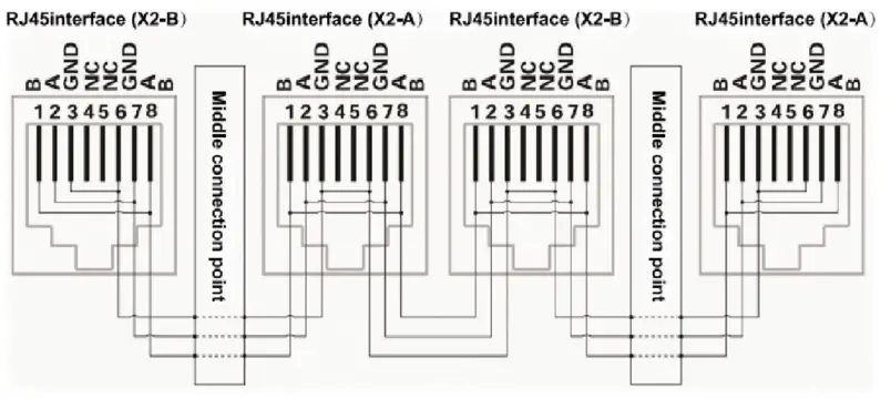
RS485 PARALLEL WIRING DIAGRAM
- When performing multi-machine parallel communication operations, it is necessary to configure the DIP address of each PACK first.
- The dialing code adopts BCD code format, the definition is:


warning
- TO ENSURE PROPER USE OF THE BATTERY PLEASE READ
- THE MANUAL CAREFULLY BEFORE USING IT.
HANDLING
- Do not expose the battery to fire.
- Do not place the battery in a charger or equipment with wrong terminals connected.
- Avoid shorting circuiting the battery .
- Avoid excessive physical shock or vibration.
- Do not disassemble or deform the battery.
- Do not immerse in water.
- Do not mix the battery with other different makes, type, or model batteries.
- Keep out of the reach of children.
CHARGE AND DISCHARGE
- The battery must be charged with a appropriate charger/inverter only.
- Never use a modified or damaged charger.
STORAGE
- Store the battery in a cool, dry and well-ventilated area.
DISPOSAL
- Regulations vary for different countries. Dispose of in accordance with local regulations.
Battery Operation Instruction
CHARGING
- Charging current: Do not surpass the specified charging current.
- Charging voltage: Do not surpass the specified charging voltage.
- Ensure correct DC polarity before connecting the terminals.
DISCHARGING CURRENT
- The discharging current must not surpass this maximum battery specification.
BATTERY STORAGE
- The battery should store in the product specification book stipulation temperature range. If has surpasses above for six months the long time storage, suggested you should carry on additional charge to the battery.
COMPLETING
SETUP
CONGRATULATIONS
- Once all the above steps have been completed you can proceed to follow the start-up instructions given by your inverter manufacturer.
- If you have any difficulties with setting up your system, please contact our Technical Support Department via [email protected]. Be sure to include the following information in your initial email so that we can provide you with timely assistance:
- Inverter make & model
- Model & number of connected batteries
- Are your batteries in Series or Parallel?
- A brief description of your system and any issues you may be having
- If possible; images of your power system
- Contact Details, if we should need to contact you


VIEW OUR WEBSITE FOR MORE INFORMATION
- www.hubblelithium.co.za
- Information published on this manual is correct as of the date published on this manual.
- Please ensure you have the latest manual which can be obtained from our website at www.hubblelithium.co.za


