LOCKLY GUARD INGRESS 302 Smart Access Control and Doorbell Installation Guide
Product Highlights
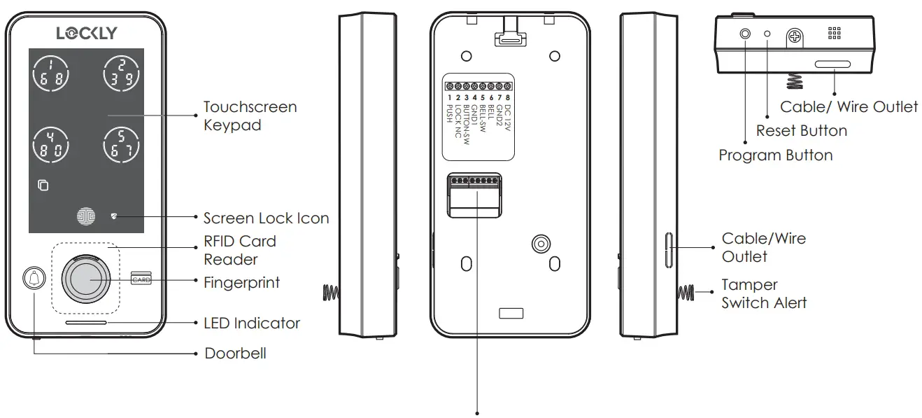
| 1 PUSH | Lock Control Port | ||
| 2 LOCKLY NC | Door Open Detection Port | ||
| 3 BUTTON-SW | Door Exit Button Port + | Wiegand 26 Data 0 | |
| 4 GND1 | Door Exit Button Port – | Doorbell Button Port | Wiegand 26 GND 1 |
| 5 BELL-SW | Doorbell Button Port + | Wiegand 26 Data 1 | |
| 6 BELL | Doorbell Signal Port | ||
| 7 GND2 | Access Control Power – | Doorbell Power – | |
| 8 DC12V | Access Control Power + | Doorbell Power + | |
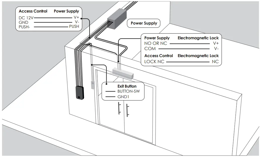
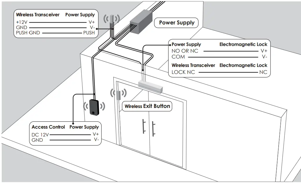
Wiring Diagram

Note: The NC port is used to detect the opening and closing status of the door. Only the Lockly Guard Electromagnetic Lock supports this function. If you use a third-party Electromagnetic Lock other than the Lockly Guard Electromagnetic Lock, you do not need to connect this NC cable.
Lockly Guard Wireless Exit Button do not require cable connection.
Wired Installation Diagram
Wireless Installation Diagram
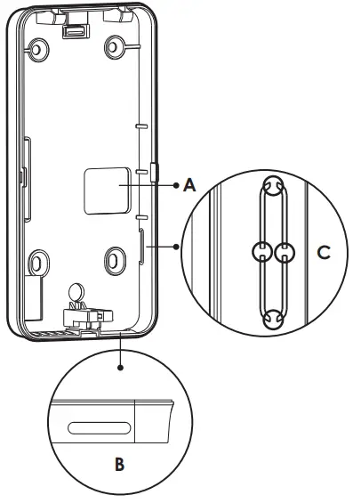
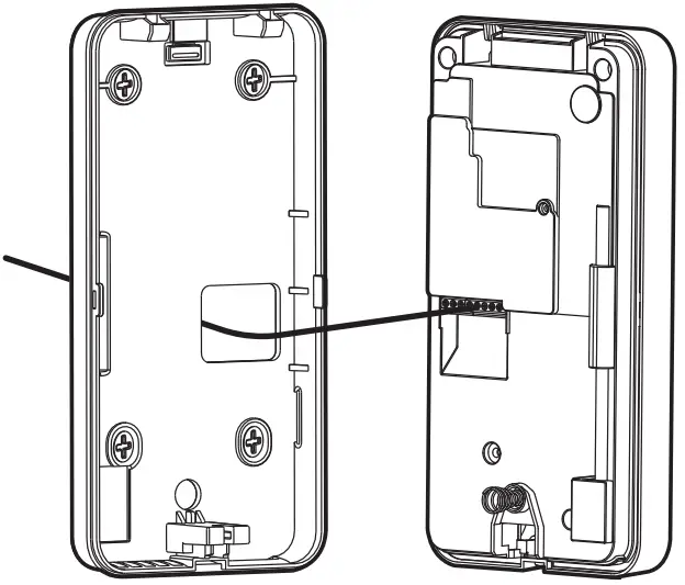
Installing the Mounting Plate
- The mounting plate has 3 wire/cable outlets. If you need to use the side outlet (C), remove the hole cover before mounting.

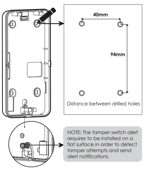
- Position the mounting plate on a flat surface or wall as to where it will be installed. Mark the 4 holes with a pencil. Drill holes with 6mm (diameter) and 30mm depth.

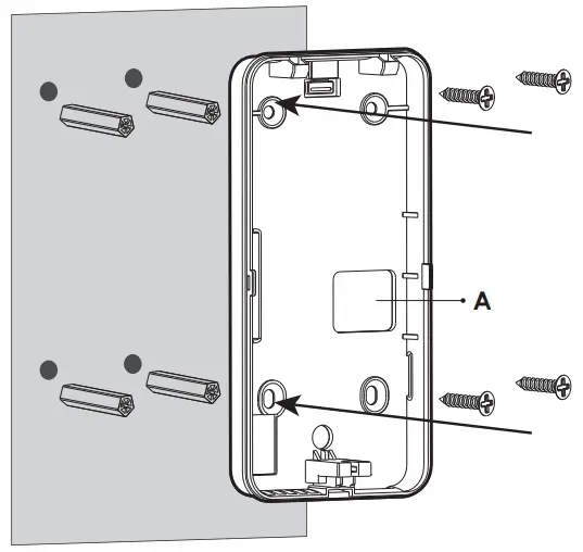
- Insert the plastic wall plugs on the drilled holes.

- If you need to pass through a cable on wire outlet (A), insert the cable first before installing the mounting plate on the wall. Secure the mounting plate with screws.

 Note: The wiring cable should be flat, not crossing or overlapping.
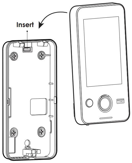
Installing Ingress Smart Access Control
- Align the Ingress device from the top of the mounting plate then insert till it reaches the bottom of the plate. Ensure the device is completely tucked.

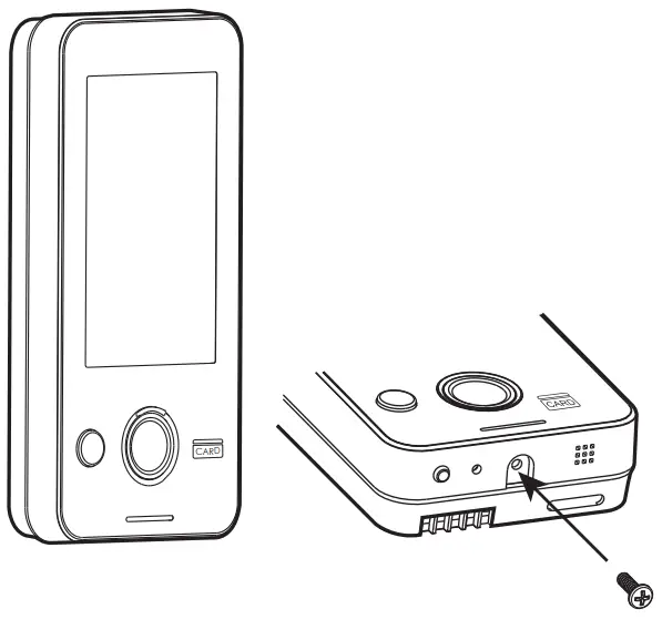
- Secure the device with a screw at the bottom.

DISCLAIMER
Lockly has made every effort at the time of publication to ensure the accuracy of the information provided herein, product specifications, configurations, system, components and options availability are all subject to change without notice to improve features, reliability or design or otherwise. For more information, please visit: www.locklyPro.com
Support
FOR COMMERCIAL USE & PROFESSIONAL INSTALLATION
We’re here to help!
[email protected]
locklypro.com/support
© Copyright 2022 Lockly All rights reserved
USA Patent NO. US 9,881,146 B2, USA Patent NO. US 9,853,815 B2
USA Patent NO. US 9,875,350 B2, USA Patent NO. US 9,665,706 B2
USA Patent NO. US 11,010,463 B2, AU Patent NO. 2013403169
AU Patent NO. 2014391959, AU Patent NO. 2016412123
UK Patent NO. EP3059689B1, UK Patent NO. EP3176722B1
Other Patents Pending
The Bluetooth® word mark and logos are registered trademarks owned by the Bluetooth SIG, Inc. , and any use of such marks by Lockly is under license. Other trademarks and trade names are those of their respective owners. Google, Android and Google Play are trademarks of Google LLC.
![]()


