MPS TBMA Test Board for the MagAlpha
DESCRIPTION
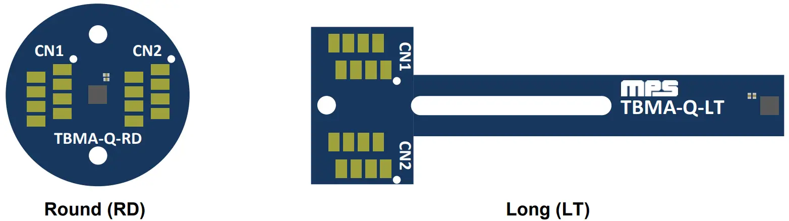
The TBMA is a test board for the MagAlpha magnetic position sensor family. The TBMA allows users to run and test MagAlpha sensors quickly. TBMA boards come in two different formats: round (RD) and long (LT). In the RD format, the sensor is mounted in an end-ofshaft configuration. In the LT format, the sensor is mounted on the edge of the board and can be used in both side-shaft and end-of-shaft configurations.
The TBMA is compatible with the Macom kit, offering seamless connection and operation of the MagAlpha and allowing users to evaluate MagAlpha functionalities and performances with their own set-up.
Contrary to the EVMA, the TBMA test board only includes the assembled board with the sensor and decoupling capacitors. It does not include connectors.
FEATURES
- Round Board Format for End-of-Shaft Mounting
- Long Board Format for Side Shaft and Endof-Shaft Mounting
- Compatible with MagAlpha Communication Interface Kit (EVKT-MACOM)
APPLICATIONS
- Servo Drives
- Robotics
- Automotive
- BLDC Motor Commutation
- Encoders
All MPS parts are lead-free, halogen-free, and adhere to the RoHS directive. For MPS green status, please visit the MPS website under Quality Assurance. “MPS” and “The Future of Analog IC Technology” are registered trademarks of Monolithic Power Systems, Inc.
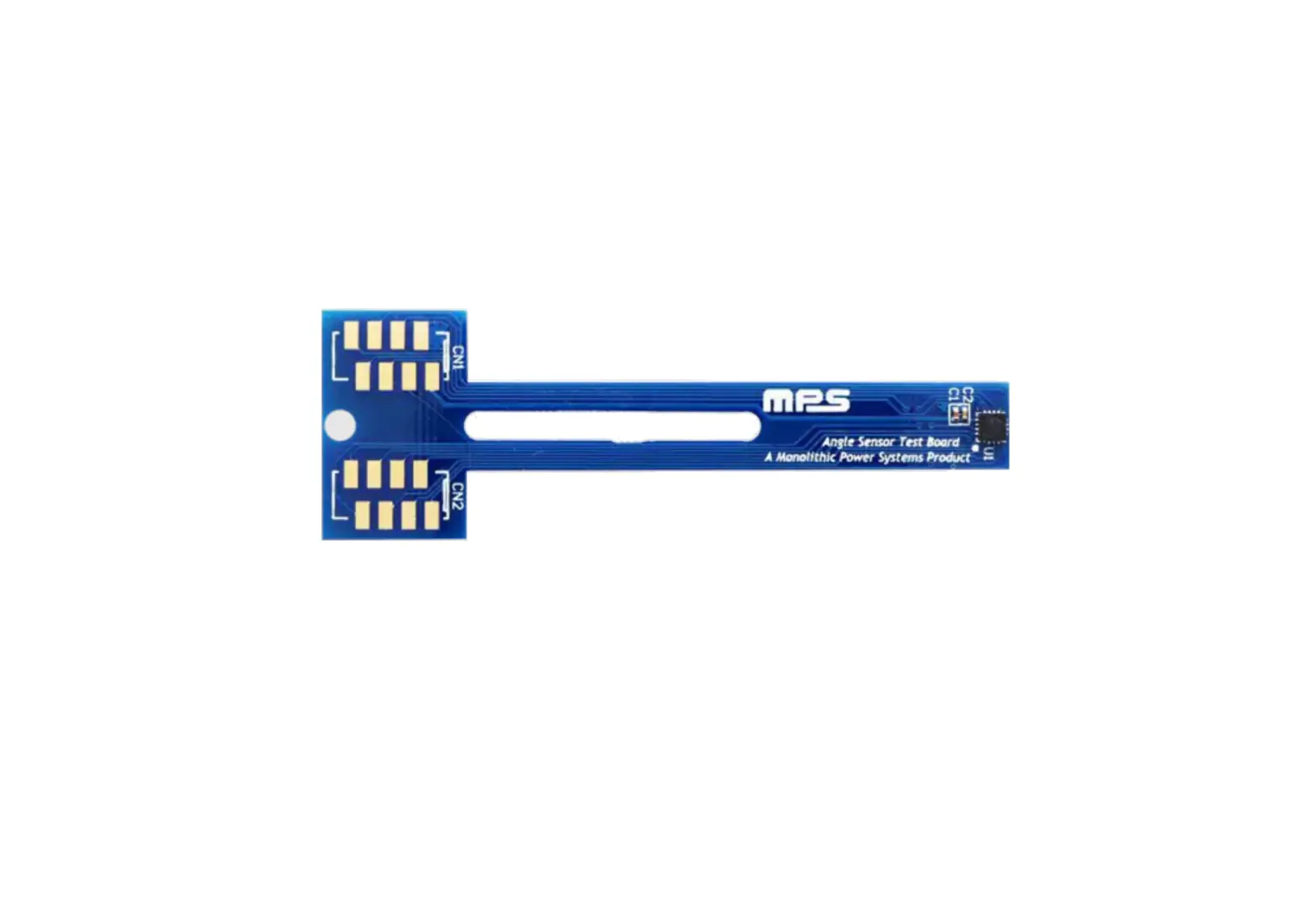
OVERVIEW
- Figure 1: TBMA

BOARD TYPE
Different board types are available, and each has a different schematic and layout design (see Table 1). The board type to use is determined by the selected sensor part number.
Each board type is also available in two different formats: a round shape test board (RD), or a long shape test board (LT). The board part number specifies which format is used:
- TBMAXXX-Q-RD-XXX = round shape test board
- TBMAXXX-Q-LT-XXX = long shape test board
Both RD and LT board formats can be used for end-of-shaft configurations where the sensor is positioned at the end of the motor or knob shaft. For side-shaft configurations where the sensor is positioned perpendicularly to the motor or knob shaft, only the RD board format can be used.
Table 1: Board Type
| Board Type | Board Part Number | MPS Chip Part Number |
| Board type 1 | TBMA100-Q-RD-00A | MA100 |
| TBMA100-Q-LT-00A | ||
| TBMA300-Q-RD-00A | MA300 | |
| TBMA300-Q-LT-00A | ||
| TBMA700-Q-RD-00A | MA700 | |
| TBMA700-Q-LT-00A | ||
| TBMA750-Q-RD-00A | MA750 | |
| TBMA750-Q-LT-00A | ||
| NOTE: Availability of this option depends of the chip part ID. Please refer to the part datasheet directly. Board type 2 NOTE: Availability of this option depends of the chip part ID. Please refer to the part datasheet directly. | TBMA102-Q-RD-01A | MA102 |
| TBMA102-Q-LT-01A | ||
| TBMA302-Q-RD-01A | MA302 | |
| TBMA302-Q-LT-01A | ||
| TBMA310-Q-RD-01A | MA310 | |
| TBMA310-Q-LT-01A | ||
| TBMA702-Q-RD-01A | MA702 | |
| TBMA702-Q-LT-01A | ||
| TBMA710-Q-RD-01A | MA710 | |
| TBMA710-Q-LT-01A | ||
| TBMA730-Q-RD-01A | MA730 | |
| TBMA730-Q-LT-01A | ||
| TBMA800-Q-RD-01A | MA800 | |
| TBMA800-Q-LT-01A | ||
| TBMA820-Q-RD-01A | MA820 | |
| TBMA820-Q-LT-01A | ||
| TBMA850-Q-RD-01A | MA850 | |
| TBMA850-Q-LT-01A |
TBMA CONTENT
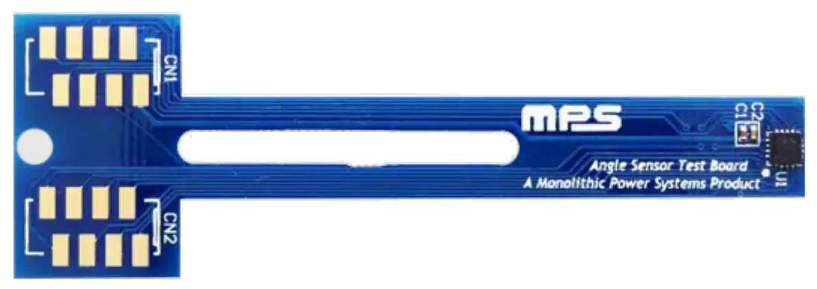
Figure 2 shows a list of TBMA test board contents.
Figure 2: Kit Contents
- One TBMA board with MagAlpha mounted (RD or LT)
- Decoupling capacitors
- Connector footprints (connectors not included)
BOARD TYPE 1
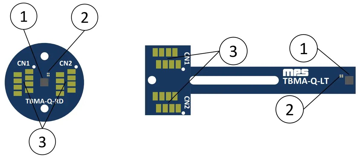
RD Format Overview
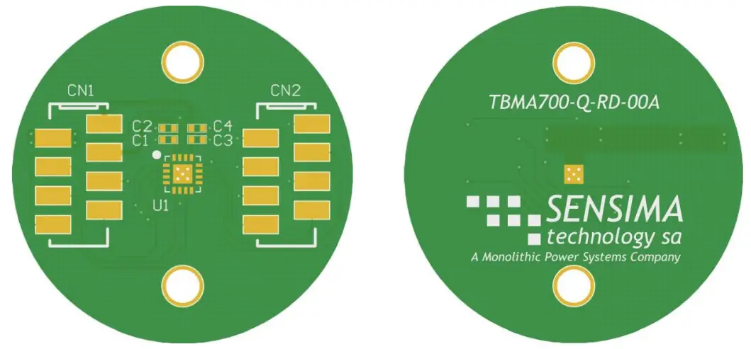
Figure 3 shows an overview of the Type 1 round (RD) board type.
Figure 3: RD Board Overview Type 1
LT Format Overview
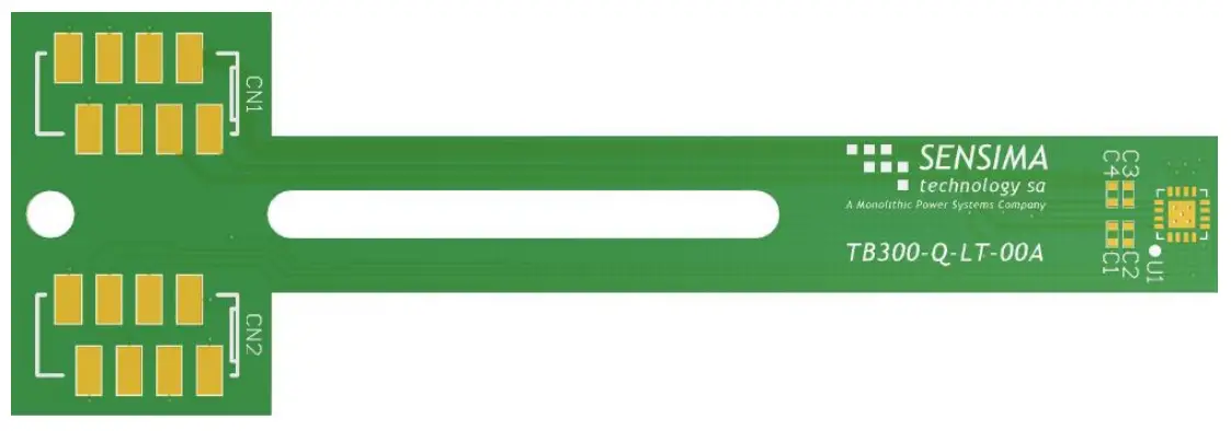
Figure 4 shows an overview of the Type 1 long (LT) board type.
Figure 4: LT Board Overview Type 1
Schematic
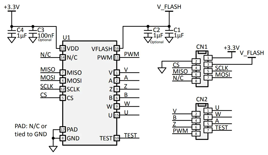
Figure 5 shows a schematic for the Type 1 board.
Figure 5: Schematic Type 1
Bill of Materials
The Type 1 board bill of materials (BOM) is shown in Table 2.
Table 2: Bill of Materials Type 1
| Quantity | Designator | Description | Value | Manufacturer | Manufacturer PN |
| 2 | C1, C4 | Ceramic Capacitor; 10V; X6S; 0402 | 1µF | Murata | GRM155C81A105KA12D |
| 1 | C2 (optional) | Ceramic Capacitor; 10V; X6S; 0402 | 1µF | Murata | GRM155C81A105KA12D |
| 1 | C3 (optional) | Ceramic Capacitor; 16V; X7R; 0402 | 100nF | Murata | GRM155R71C104KA88J |
| 1 | U1 | MagAlpha Magnetic Position Sensor | MAxxx | MPS | |
| 2 | CN1, CN2 (not populated) | 8 Position Receptacle Connector 0.100″ (2.54mm), Surface Mount Tin | Würth Elektronik or TE Connectivity | 690367280876 or 7-2178711-8 |
Assembly View
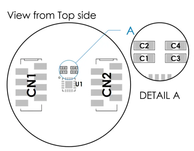
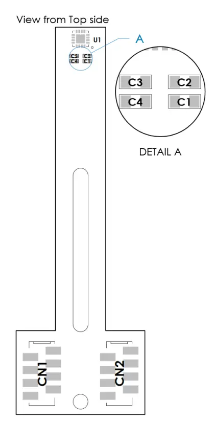
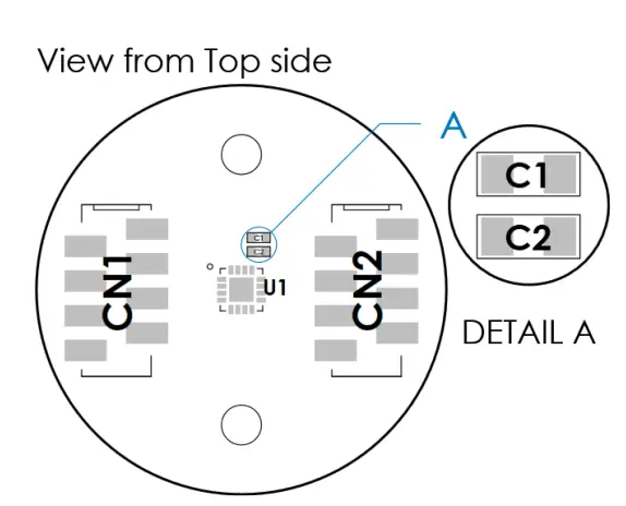
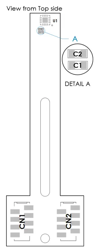
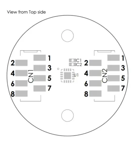
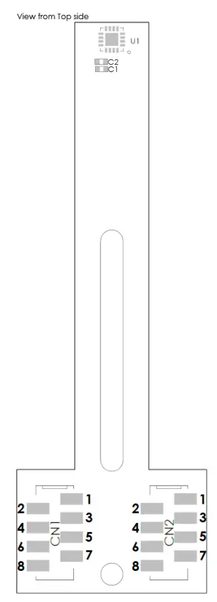
Figure 6 shows the top side assembly view of the Type 1 round board. Figure 7 shows the top side assembly view of the Type 1 long board.
- Figure 6: Assembly View RD Type 1

- Figure 7: Assembly View LT Type 1

Mechanical Drawing
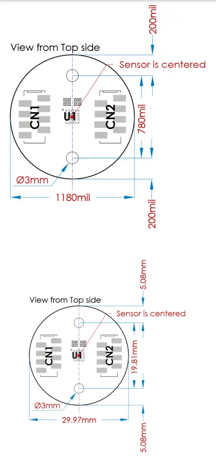
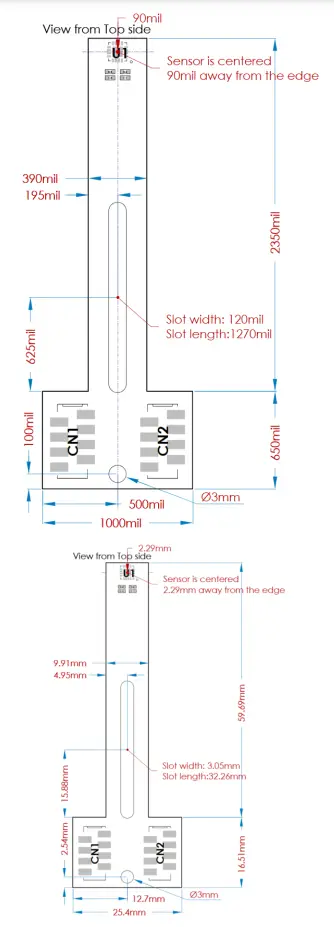
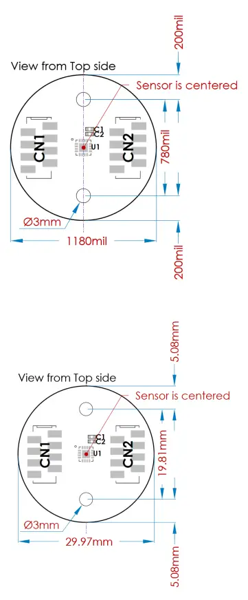
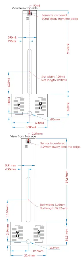
Figure 8 shows the top side mechanical drawing of the round board. Figure 9 shows the top side mechanical view of the long board.
- Figure 8: Mechanical Drawing RD Type 1

- Figure 9: Mechanical Drawing LT Type 1 mil = 0.001in = 0.0254mm

Connector Pinout
Figure 10 shows the connector pinout of the Type 1 round board. Figure 11 shows the connector pinout for the Type 1 long board.
- Figure 10: Connector RD Pinout Type 1

- Figure 11: Connector LT Pinout Type 1

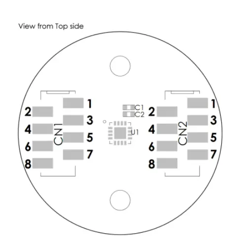
See Table 3 for Type 1 pin registers.
Table 3: Connector Pin Mapping Type 1
| Pin | Name | Description |
| CN1.1 | VDD | 3.3V supply. |
| CN1.2 | GND | Ground. |
| CN1.3 | VFLASH | Flash power supply (3.9V only powered during flashing). |
| CN1.4 | CS | Chip select (serial). |
| CN1.5 | SCLK | Clock (serial). |
| CN1.6 | MISO | Master in slave out (serial). |
| CN1.7 | MOSI | Master out slave in (serial). |
| CN1.8 | – | Leave unconnected. |
| CN2.1 | U (1) | U output (optional motor commutation). |
| CN2.2 | V (1) | V output (optional motor commutation). |
| CN2.3 | W (1) | W output (optional motor commutation). |
| CN2.4 | A (1) | A output (optional incremental encoder). |
| CN2.5 | B (1) | B output (optional incremental encoder). |
| CN2.6 | Z (1) | Z output (optional incremental encoder). |
| CN2.7 | TEST | Test pin. |
| CN2.8 | PWM (1) | Pulse width modulation output (optional). |
NOTE
1) Availability of this option depends of the chip part ID. Please refer to the part datasheet directly.
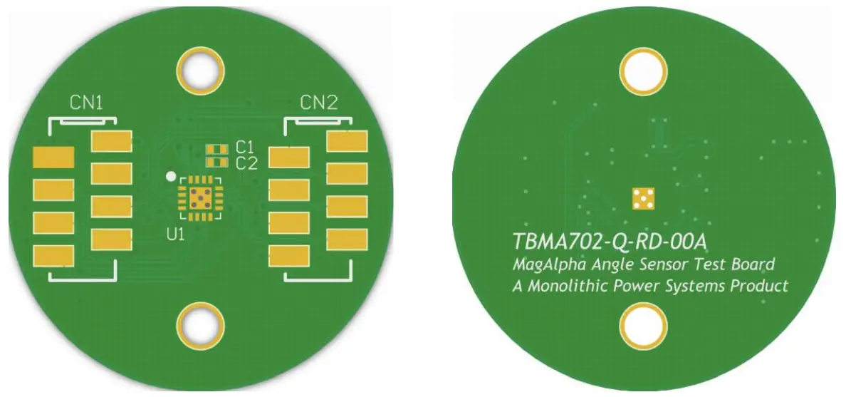
BOARD TYPE 2
RD Format Overview
Figure 12 shows an overview of the Type 2 round (RD) board type.
Figure 12: RD Board Overview Type 2
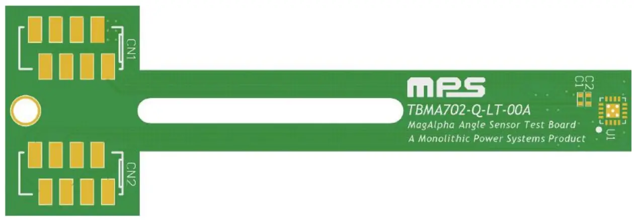
LT Format Overview
Figure 13 shows an overview of the Type 2 long (LT) board type.
Figure 13: LT Board Overview Type 2
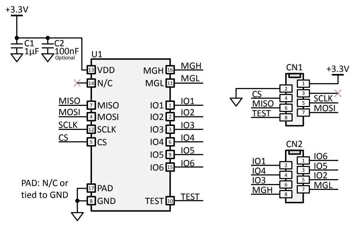
Schematic
Figure 14 shows a schematic for the Type 2 board.
Figure 14: Schematic RD/LT Type 2
Bill of Materials
The Type 2 board bill of materials (BOM) is shown in Table 4.
Table 4: Bill of Materials Type 2
| Quantity | Designator | Description | Value | Manufacturer | Manufacturer PN |
| 1 | C1 | Ceramic Capacitor; 10V; X6S; 0402 | 1µF | Murata | GRM155C81A105KA12D |
| 1 | C2 (not populated) | Ceramic capacitor; 16V; X7R; 0402 | 100nF | Murata | GRM155R71C104KA88J |
| 1 | U1 | MagAlpha Magnetic Position Sensor | MAxxx | MPS | |
| CN1, CN2 | 8 Position Receptacle | Würth Elektronik | 690367280876 | ||
| 2 | (not | Connector 0.100″ (2.54mm), | or | or | |
| populated) | Surface Mount Tin | TE Connectivity | 7-2178711-8 |
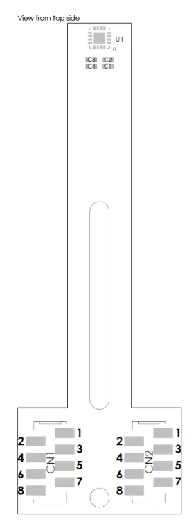
Assembly View
Figure 15 shows the top side assembly view of the Type 2 round board. Figure 16 shows the top side assembly view of the Type 2 long board.
- Figure 15: Assembly View RD Type 2

- Figure 16: Assembly View LT Type 2

Mechanical Drawing
Figure 17 shows the top side mechanical drawing of the Type 2 round board. Figure 18 shows the top side mechanical view of the Type 2 long board.
- Figure 17: Mechanical Drawing RD Type 2

- Figure 18: Mechanical Drawing LT Type 2 mil = 0.001in = 0.0254mm

Connector Pinout
Figure 19 shows the connector pinout of the Type 2 round board. Figure 20 shows the connector pinout for the Type 2 long board.
- Figure 19: Connector RD Pinout Type 2

- Figure 20: Connector LT Pinout Type 2

See Table 5 for Type 2 pin registers.
Table 5: Connector Pin Mapping Type 2
| Pin | Name | Description |
| CN1.1 | VDD | 3.3V supply. |
| CN1.2 | GND | Ground. |
| CN1.3 | – | – |
| CN1.4 | CS | Chip select (serial). |
| CN1.5 | SCLK | Clock (serial). |
| CN1.6 | MISO | Master in slave out (serial). |
| CN1.7 | MOSI | Master out slave in (serial). |
| CN1.8 | TEST | Test pin. |
| CN2.1 | IO6 (2) | Pin 15 (IO). |
| CN2.2 | IO1 (2) | Pin 1 (IO). |
| CN2.3 | IO5(2) | Pin 9 (IO). |
| CN2.4 | IO4 (2) | Pin 6 (IO). |
| CN2.5 | IO2 (2) | Pin 2 (IO). |
| CN2.6 | IO3 (2) | Pin 3 (IO). |
| CN2.7 | MGL (3) | Magnetic level low (optional). |
| CN2.8 | MGH (3) | Magnetic level high (optional). |
NOTES:
2) Please, refer directly to the chip datasheet to know which features are available on these pins.
3) Availability of this option depends of the chip part ID. Please refer to the part datasheet directly.
MAGNET SUPPLIERS
Table 6 shows a non-exhaustive list of possible magnet suppliers. The magnetization direction must be chosen wisely given the fact that most sold magnets are often axially magnetized, which is not a magnetization direction usually required in magnetic angle sensing applications. Angle sensing applications typically use diametrically magnetized magnets.
Table 6: Magnet Suppliers
| Company | Website | Address |
| Maurer Magnetics AG | www.maurermagnetic.ch | Industriestrasse 8 8627 Grüningen Switzerland |
| Arnold Technologies AG | www.arnoldmagnetics.com | Hübelacherstrasse 15 5242 Birr-Lupfig Switzerland |
| Bomatec AG | www.bomatec.com | Hofstrasse 1 8181 Höri Switzerland |
| Dexter Magnetic Technologies | www.dextermag.com | 1050 Morse Avenue Elk Grove Village, IL 60007-5110 USA |
| JPMF | www.jpmf.com.cn | 8 LongWan Road Jiangmen City GuangDong Province China |
| Binicmagnet | www.binicmagnet.com | Unit 612 Yuanzhong Building No. 1905 Hongmei Road Shanghai P. R. China 200233 |
| China Rare Earth Magnet | www.permanentmagnet.com | Room 705, Tower A Century Holiday Plaza 9030 Shennan Rd Nanshan District Shenzhen China |
| Goudsmit Magnetic Systems | www.goudsmit-magnetics.nl | Petunialaan 19 5582 HA Waalre Netherland |
Maurer Magnetic
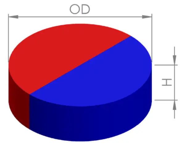
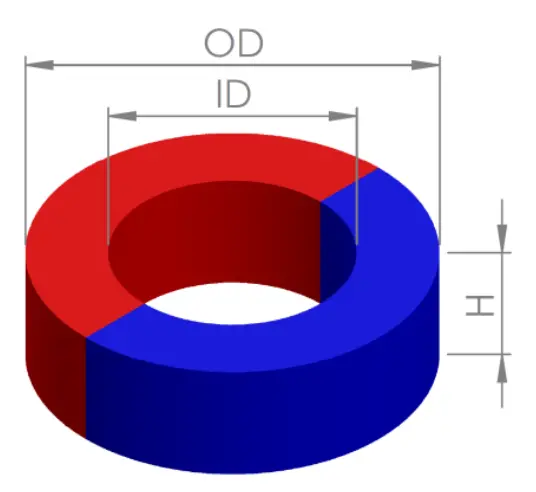
Maurer Magnetic has a selection of diametrically magnetized magnets well-suited for contactless rotary angle applications (see Figure 21 and Figure 22). Samples of the types mentioned below should always be available with no lead time.
- Figure 21: Cylinder Magnet, Diametrically Magnetized

- Figure 22: Ring Magnet, Diametrically Magnetized

See Table 7 for a list of Maurer Magnetic magnets.
Table 7: Maurer Magnetic Diametrically Magnetized Magnets
| OD (mm) | ID (mm) | H (mm) | Material | Remanence (Br) (T) | Magnetization | Part Number |
| 4.0 | – | 3.0 | N35 | 1.2 | Diametrical | M610403 |
| 4.0 | – | 3.0 | Sm26/16-17 | 1.08 | Diametrical | M410403 |
| 5.0 | – | 2.5 | N35 | 1.2 | Diametrical | M610502 |
| 5.0 | – | 2.5 | Sm26/16-17 | 1.08 | Diametrical | M410502 |
| 5.0 | 1.25 | 2.5 | N35 | 1.2 | Diametrical | M610512 |
| 5.0 | 1.25 | 2.5 | Sm26/16-17 | 1.08 | Diametrical | M410512 |
| 6.0 | – | 2.5 | N35 | 1.2 | Diametrical | M610602 |
| 6.0 | – | 2.5 | Sm26/16-17 | 1.08 | Diametrical | M410602 |
| 6.0 | 1.5 | 2.5 | N35 | 1.2 | Diametrical | M610612 |
| 6.0 | 1.5 | 2.5 | Sm26/16-17 | 1.08 | Diametrical | M410612 |
| 6.0 | 1.5 | 3.0 | N35 | 1.2 | Diametrical | M610613 |
| 6.0 | 1.5 | 3.0 | Sm26/16-17 | 1.08 | Diametrical | M410613 |
| 8.0 | – | 2.5 | N35 | 1.2 | Diametrical | M610802 |
| 8.0 | – | 2.5 | Sm26/16-17 | 1.08 | Diametrical | M410802 |
NOTICE: The information in this document is subject to change without notice. Users should warrant and guarantee that third party Intellectual Property rights are not infringed upon when integrating MPS products into any application. MPS will not assume any legal responsibility for any said applications.
Customer Support
www.MonolithicPower.com
MPS Proprietary Information. Patent Protected. Unauthorized Photocopy and Duplication Prohibited.
© 2017 MPS. All Rights Reserved.

References
 Industrial Magnet Manufacturer | Arnold Magnetic Technologies
-
BINIC MAGNET Co.,LTD
-
Home - Bomatec
 Permanent Magnet & Custom Magnetic Assemblies | Quality Manufacturer
-
Driven by magnetism | Goudsmit Magnetics
-
江益磁材
-
Maurer Magnetic AG - Home
 MPS | Monolithic Power Systems
-
Permanent Magnets - China Rare Earth Permanent Magnet Manufacturers


