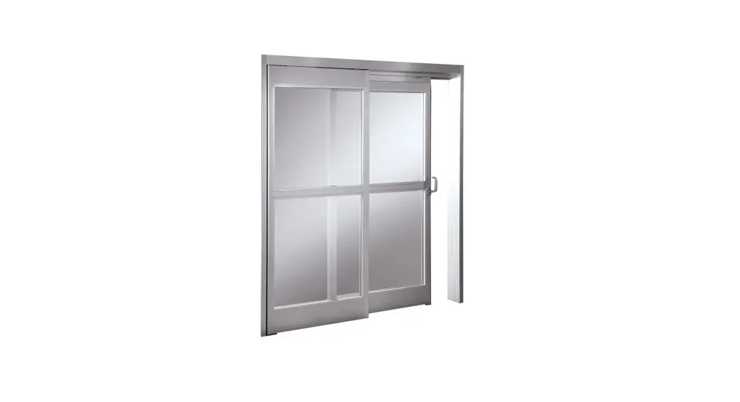
![]() ICU300 ICU300T Sliding Doors with Track Guide System
ICU300 ICU300T Sliding Doors with Track Guide System
Installation Guide
ICU300/ ICU300T Sliding Doors with Track Guide System
Tools Required:
Screwdrivers Small Straight (Flat Blade) – for Terminal Block wiring #2 Phillips (Crosspoint) – for various #8, #10, and #14 screws
Wrenches / Sockets
15/16″ wrench – for carrier and anti-rise roller adjustment
Allen Wrenches
3mm – for “SX” & “SO” roller catch adjustment
1/8” – for “SO” arm stop & “SX” bottom pivot
5/32” – for “SO” top pivot
5mm (3/16”) – for “SO” arm pivot screw
7/32″ – for “SX” breakout adjustment
5/16″ – for carrier and anti-rise roller adjustment
Electric Drill with the following drill bits 9/64″(or
#28) – for installing sensors & “SO” bottom roller stop
5/32″ (or #22) – for installing #10 sheet metal screws into adjacent storefront
13/64″ (or #7) – for installing #14 sheet metal screws into adjacent storefront
1/4″ – for clearance holes in jambs 82 degree Countersink
Impact Drill with the following masonry bits 1/4″
– for #10 screw anchors
5/16″ – for #14 screw anchors
Level – suggested 4′ minimum
Step Ladder – 4′ or 6′ Tape Measure
Caulking and Application Gun
Electrical Wire Strippers /Cutters – for monitor wiring
Grease [to hold “SX” bottom guide block on shaft]
BEA Universal Remote Control – for adjusting sensors
Suggested Fasteners Required – (Not supplied)
Jamb Attachment Screws #14
X 2-1/2″ PHSMS (Pocket Jambs)
#14 X 3″ FHSMS (Tube Jambs)
Optional Anchors for masonry
Threshold Attachment Screws
#10 X 1-1/2″ FHSMS
Optional Anchors for masonry
Header Attachment Screws
#14 X 1-1/2″ HHSMS
#14 Flat Washer
Construction Shims – for squaring door frame in opening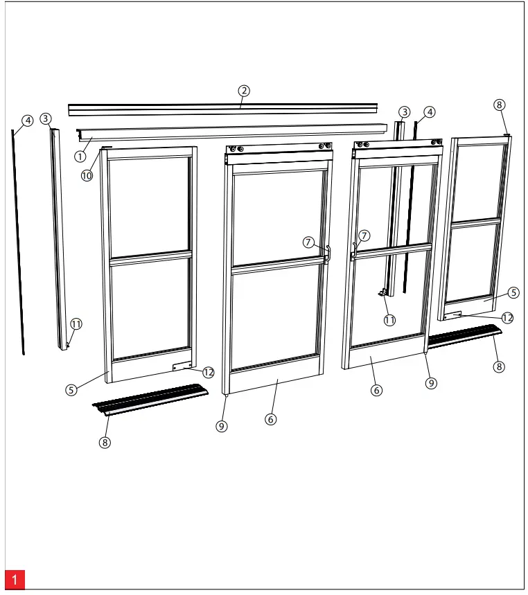
Components (2 Leaf) – Overview
| 1 Header | 5 Sidelight | 9 Floor Guide |
| 2 Header Closeout Cover | 6 Sliding Panel | 10 Bearing Pivot Top |
| 3 Jamb Tube | 7 Positive Latch Pull | 11 Bearing Pivot Bottom |
| 4 Cover Extrusion | 8 Floor Rail | 12 Latch Device |
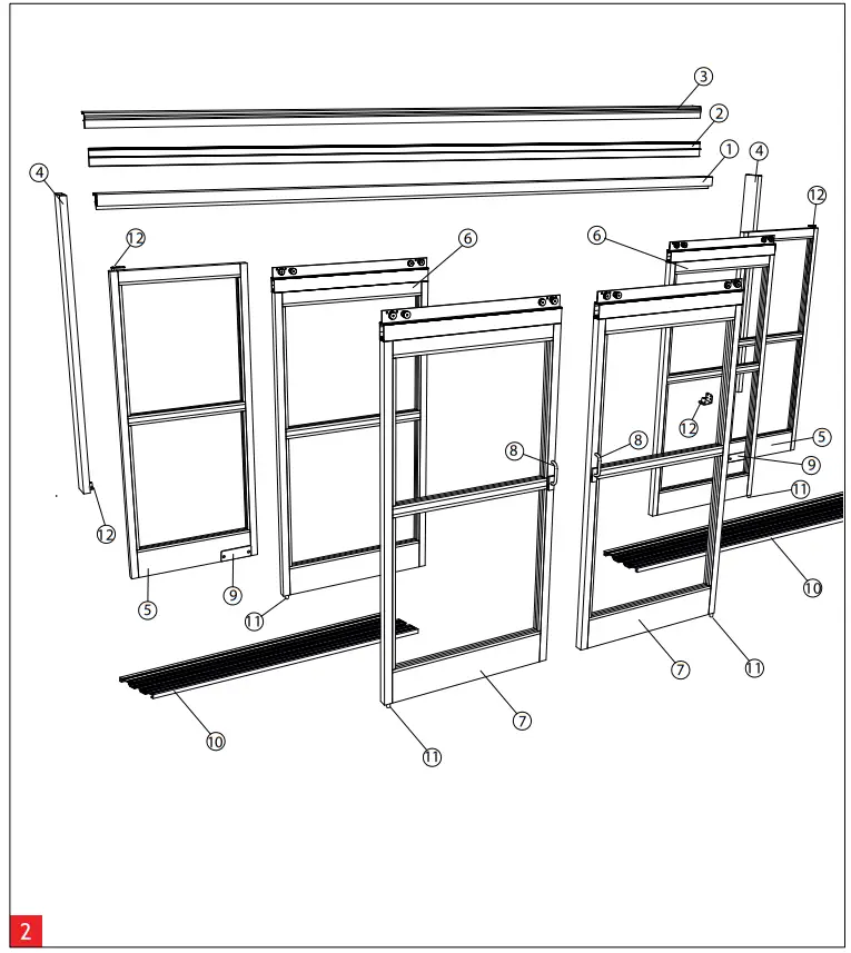 Components (4 Leaf) – Overview
| 1 Header | 5 Sidelight | 9 Latch Device |
| 2 Header Closeout Cover | 6 “SX2” Sliding Panel | 10 Floor Rail (2 Track) |
| 3 Outer Roller Track | 7 “SX1” Sliding Panel | 11 Floor Guide |
| 4 Jamb Tube | 8 Positive Latch Pull | 12 Bearing Pivot |
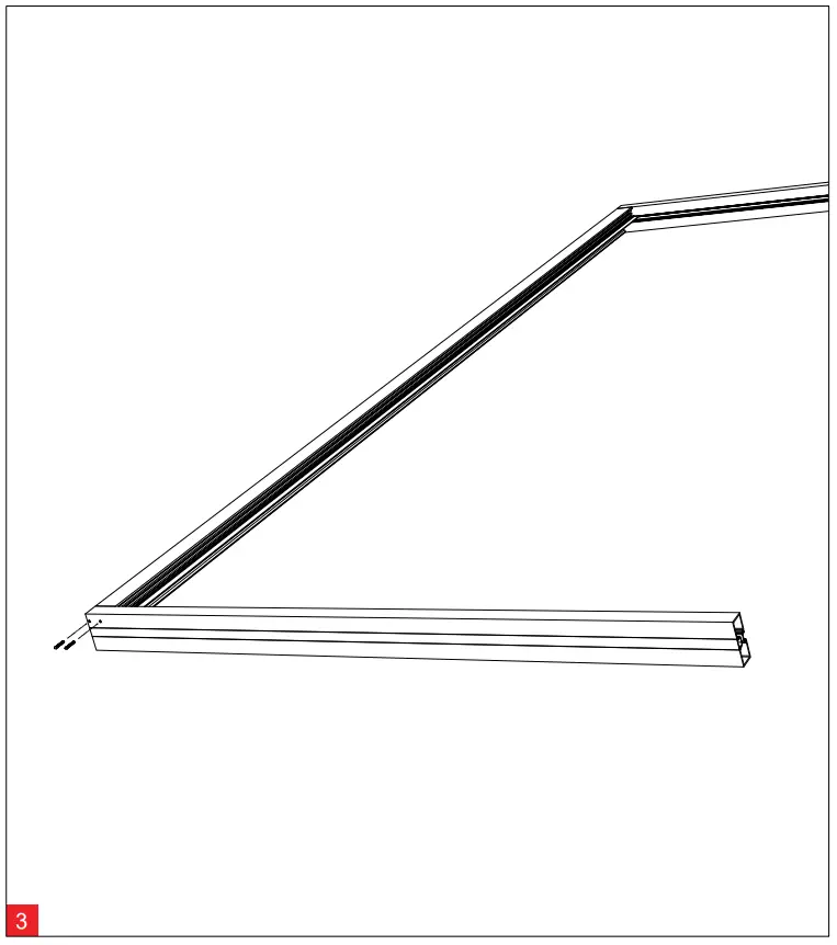
Header to Jamb Assembly
Fasten the header unit to the jambs using (4) #10 x 1” phillips pan heads (2 per side). (#2 Phillips screw driver required.)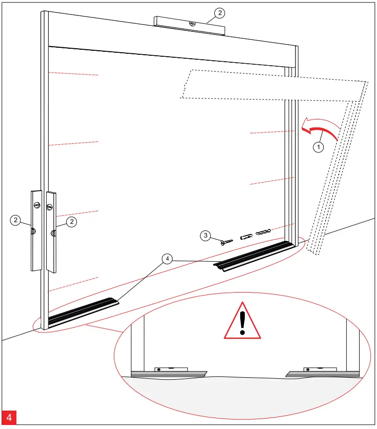
Assembly
- Place the header & jamb assembly into the rough opening.
- Level all sides and shim as required.
- Fasten assembly into rough opening, after verifying unit is level and plumb in all directions.
- Place floor track in position.
![]() Find highest floor elevation and shim accordingly.
Find highest floor elevation and shim accordingly.![]() The mounting of the unit to the rough opening must meet applicable building codes and standards.
The mounting of the unit to the rough opening must meet applicable building codes and standards.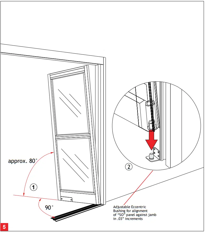 Sidelight mounting
1 – 2 Align “SO” panel 90° to the “SX” track and 80° to the vertical jamb. Place “SO” panel onto bottom pivot mounted on the jamb.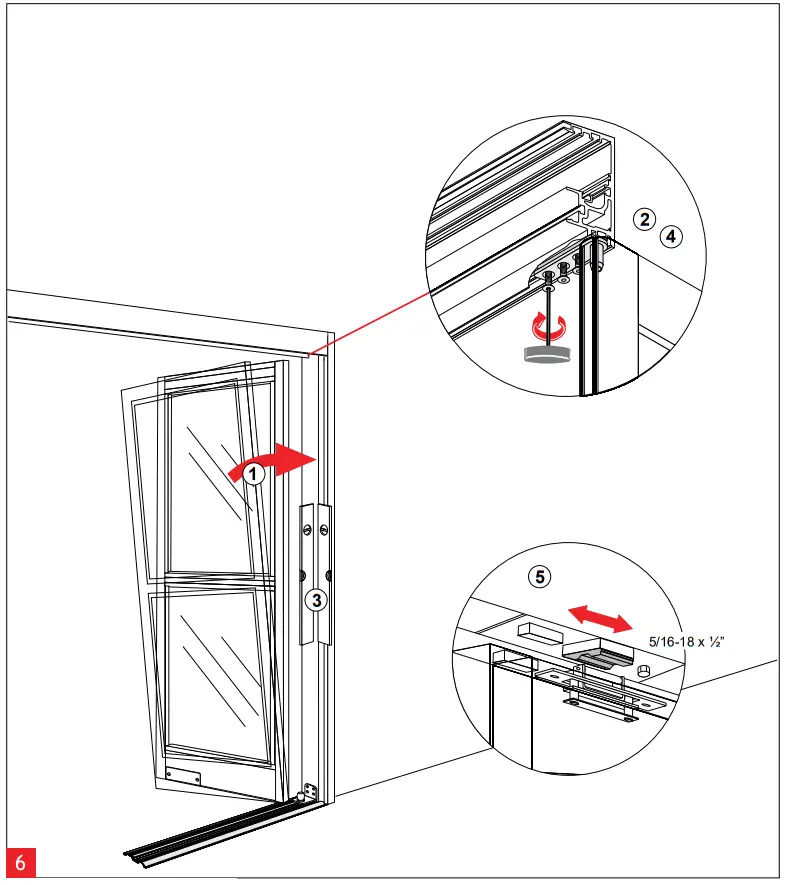 Securing the Sidelight
- Push “SO” Panel vertically to align with jamb.
- Rotate upper “SO” arm and lightly fasten to screw plate located in header.
- Align and plumb “SO” Panel.
- Tighten (3) 1/4-20 x 5/8 fasteners in “SO” top pivot, securing “SO” Panel to header using 5/32” Allen wrench.
- Loosen fastener. Close “SO” panel and align “SO” magnet/latch sub-assembly. Tighten fastener using ½” socket/wrench. For roller catch tension adjustment, see Page 14.
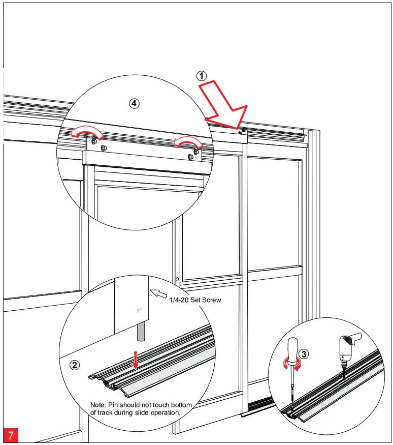 Hanging the “SX” or “SX2” panel
- Lift ”SX” or “SX2” panel and place rollers onto roller track in header.
- Find the highest spot along track. Place small screwdriver below “SX” pivot, loosen set screw and re-tighten when “SX” bottom guide pin reaches screwdriver (1/8” Allen required).
- Align track with jamb. Fasten and anchor bottom track to floor.
- Adjust “SX” or “SX2” panel (refer to page 11).
![]() When installing a telescopic unit, you must adjust door height completely before proceding to next step
When installing a telescopic unit, you must adjust door height completely before proceding to next step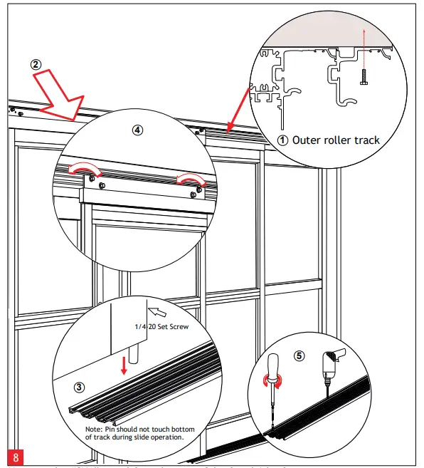 Hanging the “SX1” panel for telescopic 3 leaf and 6 leaf units
- Install outer roller track by fastening into masonary opening.
- Lift “SX1” panel and place rollers onto outer roller track.
- Find the highest spot along track. Place small screwdriver below “SX1” pivot, lossen set screw and re-tighten when “SX1” (1/8” Allen required). bottom guide pin reaches screwdriver (1/8” Allen required).
- Adjust “SX1” panel (refer to Page 11).
- Align track with jamb. Fasten and anchor bottom track to floor.
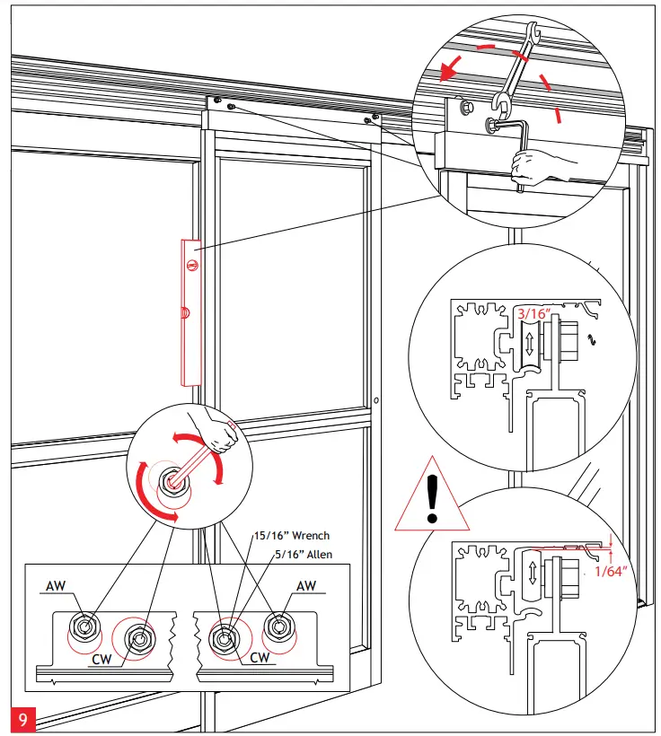 Vertical Alignment for “SX1” and “SX2” panels
Using the eccentric carrier wheel (CW), and the anti-riser wheel (AW), level the sliding panel. Tighten hex nuts to secure the adjustment.![]() Adjustment of the anti-riser roller:
Adjustment of the anti-riser roller:
The anti-riser roller should not contact the top track anywhere along the slide path of the door.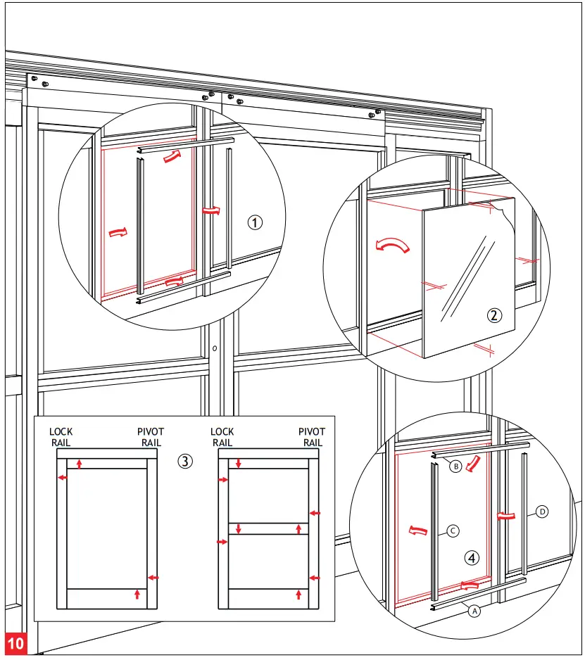 Glazing
- Remove the glass stops from exterior side (4 per opening).
- Center the glass in opening.
- Properly block and/or cushion glass edges.
- Press the glass stops into place starting with the horizontal stops, then follow with the vertical stops.
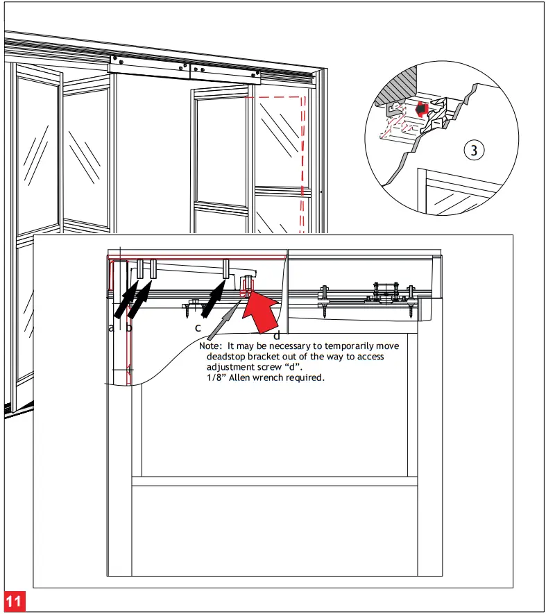 Adjustment of the Breakout-Unit
- Loosen the set screws (a ,b&c)toprevent interference while adjusting door. (7/32” Allen wrench required.)
- Use the adjustment screw (d) to lift (CW) , or lower (CCW) , the leading edge of door.
- Continue adjustment until the re-latch profiles are properly aligned.
- Tighten all set screws (a, b & c) until tight and secure.
Recheck the latched position alignment and readjust as necessary.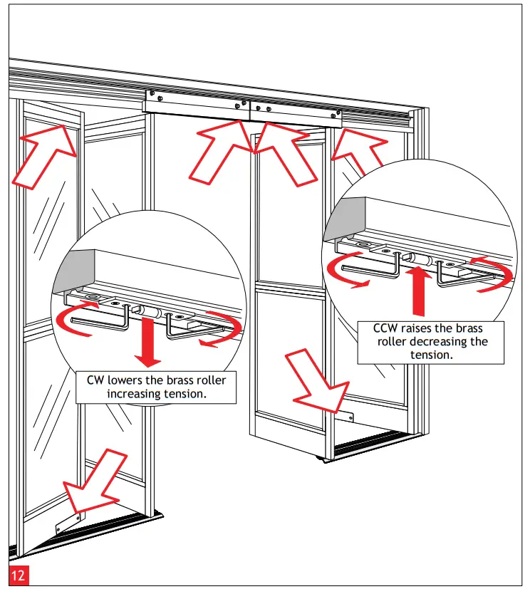 Adjustment of the Roller Catch
Align the roller catches, as illustrated, using the adjustment screws. (3mm Allen wrench tool required.)
Pay close attention to the disengagement or breakout force.
Do not exceed ANSI A156.10 Standards.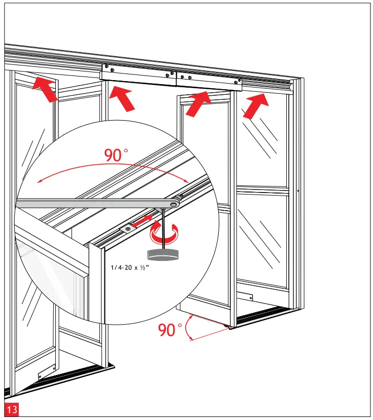 “SX1”, “SX2”, and “SO” Panel Breakout Adjustment
- Open “SX” & “SO” panels to 90°.
- Move arm stop blocks to engage arm. (1/8” Allen wrench required.)
- Secure stop blocks.
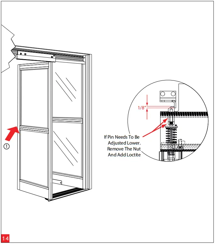 Positive Latch Adjustment
- Remove astragral on side of door.
- Adjust pin to provide 1/8” (3.2mm) of Latch Pin Engagement.
- Test door for proper Latch operation and Breakout function.
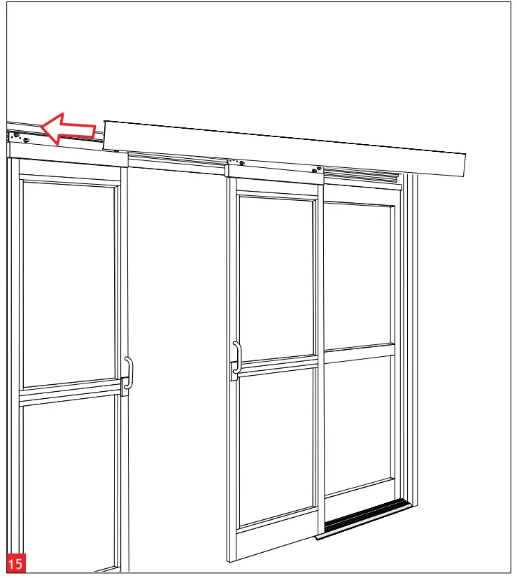
Install Closeout Cover
Attach Closeout Cover using 1/4” – 20 screws, one on either end.![]() Ensure proper operation of door before installing Closeout Cover. If door is latched shut without proper Positive Latch adjustment, door will not open and Closeout Cover will be difficult to remove.
Ensure proper operation of door before installing Closeout Cover. If door is latched shut without proper Positive Latch adjustment, door will not open and Closeout Cover will be difficult to remove.![]()
dormakaba USA, Inc.
1 Dorma Drive, Drawer AC
Reamstown, PA 17567
USA
T: 717-336-3881
F: 717-336-2106
www.dormakaba.us


