![]() 200 CI2 Series Gas Condensing Boilers with Matrix Cylinder Burners
200 CI2 Series Gas Condensing Boilers with Matrix Cylinder Burners
Installation Guide
Installation and Start-up Guide
for use by a licensed professional heating contractor for typical single boiler installations
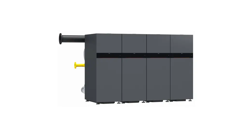
Vitocrossal 200 CI2 series
Gas condensing boilers with MatriX cylinder burners
Heating input: 399 to 2000 MBH (117 to 586 kW)
Before you install the boiler;
This boiler is configured for Natural Gas from the factory. If conversion to Propane Gas is required, the conversion kit supplied with the boiler must be used.
This guide is designed to provide a quick overview to the licensed professional heating contractor for installing the Vitocrossal 200 CI2 boiler.
It is NOT a substitute for the technical support literature supplied with the boiler and accessories.
The technical support literature for each product contains the necessary safety and national/local code requirements which, if not followed exactly, may lead to property damages, personal injuries and/or loss of life. Viessmann
Manufacturing assumes no responsibility for damage(s) of any kind caused by inappropriate use of this manual and/or failure to read the technical literature provided which may also render the warranty null and void.
Codes
The installation of this unit shall be in accordance with local codes or, in the absence of local codes, use CAN/CSA-B149.1 or .2 Installation Codes for Gas Burning Appliances for Canada. For U.S. installations use the National Fuel Gas Code ANSI Z223.1. Always use latest editions of codes.
In Canada all electrical wiring is to be done in accordance with the latest edition of CSA C22.1 Part 1 and/or local codes. In the U.S. use the National Electrical Code ANSI/NFPA 70. The heating contractor must also comply with both the Standard for Controls and Safety Devices for Automatically Fired Boilers, ANSI/ASME CSD-1, and the Installation Code for Hydronic Heating Systems, CSA B21401, where required by the authority having jurisdiction.
![]()
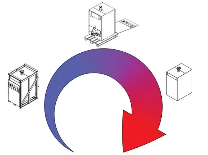
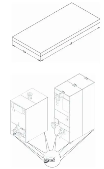
Unpacking the Boiler
The boiler is delivered on a wooden pallet.
Note: The boiler can be lifted by crane only while it is still packed on the skid.
- Remove packaging.
- Unscrew the transport brackets.
- Remove the ramp and set aside.
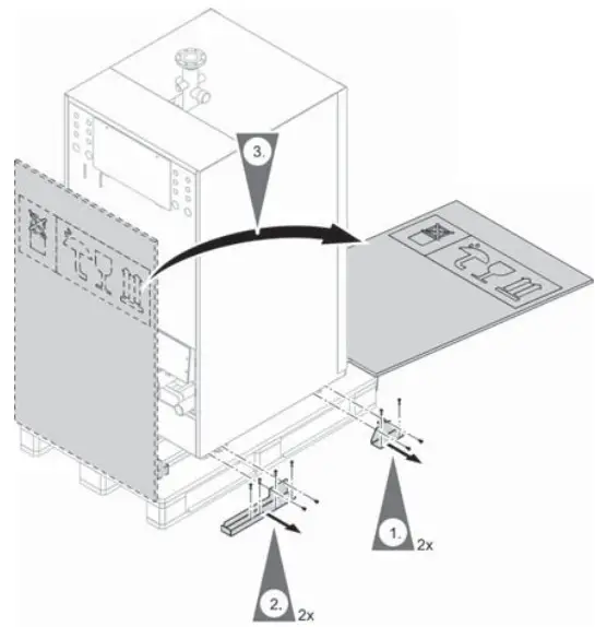
- Position the ramp at the rear of the boiler.
Ensure that there is sufficient room to unload the boiler from the skid. The ramp length A is 50 in. (1270 mm) for CI2 models 399 through 1000, and 75 in. (1900 mm) for CI2 models 1500 and 2000. CAUTION
Do not push on the jacketing to remove the boiler from the skid.
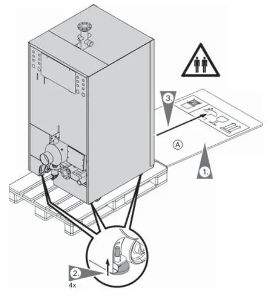
Note: The boiler is equipped with wheels to facilitate unloading and placement of the boiler. - Using an open end wrench wind in the adjustable feet.
- Roll the boiler off the pallet.WARNING
The boiler can cause serious injury if it overturns.
At least 2 people are required to move the boiler.
Roll the boiler in a straight line.
Positioning the Boiler
Note: The levelling feet must be used once the boiler has been placed in it’s final position.
- Using an open end wrench adjust the levelling feet in the base frame of the boiler ensuring that the wheels are off the ground.
- It is recommended to place a flat piece of steel plate under each leveling bolt for better weight distribution and adjustment.
- Level the boiler, by adjusting the levelling feet.

Cl2 Model 399 500 750 1000 1500 2000 a in. 32 41 471/4 mm (812) (1040) (1200) b in. 291/2 291/2 291/2 mm (750) (750) (70) Weight incl. 1027 lb. 1382 lb. 2754 lb. 2798 lb. water content 358 kg 627 kg 1249 kg 1269 kg
Accessing the Boiler
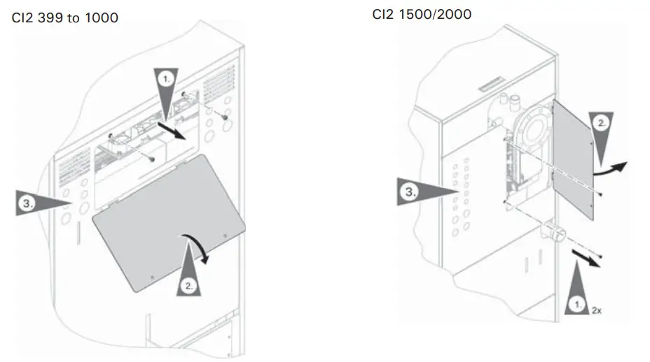
CI2 399 to 1000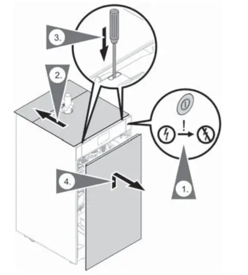 Removing the front panel
To access the BCU and control unit, panels have to be removed.
- Turn the power switch off and disconnect the power supply to the boiler, close gas shutoff valve.
- Slide the top panels towards the back, exposing the front panel release.
- Using a screwdriver, press down on the front panel release.
- Pull the top of the front panel away from the boiler, then lift up to remove.
CI2 1500/2000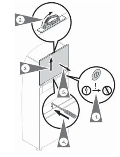
- Turn the power switch off and disconnect the power supply to the boiler close gas shutoff valve.
- Flip open the panel handle located at the top of the upper front panel.
- Pull up the upper front panel using the panel handle.
- While holding the panel handle, use a screw driver to release the panel retaining clip.
- Pull up to finish removing the panel.
CAUTION
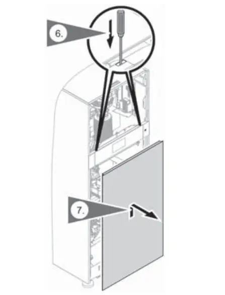
Failure to keep a firm grip on the panel handle may cause the upper front panel to fall causing injury. Removing the front panels
 - Using a screw driver, press down on the lower front panel release.
- Pull the top of the lower front panel away from the boiler, lift up to remove.
 Removing the front panels
Boiler Connections
Safety Header
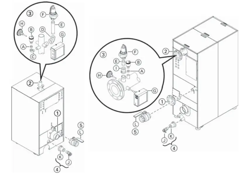
Legend
- Boiler return: 2 in. NPT for CI2 399/500
2 b in. ANSI flange for CI2 750/1000 *1 - in. ANSI flange for CI2 1500/2000 *1
2 Boiler supply: 2 in. NPT for CI2 399/500
2 b in. ANSI flange for CI2 750/1000 *1
4 in. ANSI flange for CI2 1500/2000 *1
*1 Counter flanges, gaskets and hardware (field supplied)
*2 Alternate pressure relief valves are available depending on operating pressure requirements. Contact your local
Viessmann sales representative for details. - Safety header: (Pressure relief valve, low water cutoff, automatic air vent and temperature/pressure gauge)
A Hex bushing b in. x e in.
B Air vent with shut-off base
C Street elbow c in.
D Reducing elbow 1a in. to 1 in.
E Nipple 1 in.
F Pressure relief valve, 80 psi *2
G Low water cutoff
H Temperature/pressure gauge
I Reducer 1b in. to 1 in. - Drains:
K Reducer 1b in. x c in.
J Sediment faucet c in. - Gas line fittings:
L Gas gas shut-off valve,
1b in. for models 399, 500, 750 and 1000,
2 in. for models 1500 and 2000
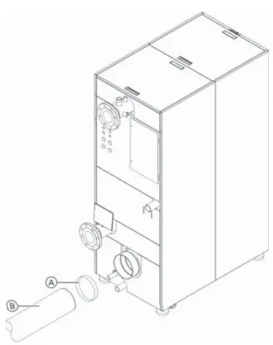
Installing the Condensate Trap
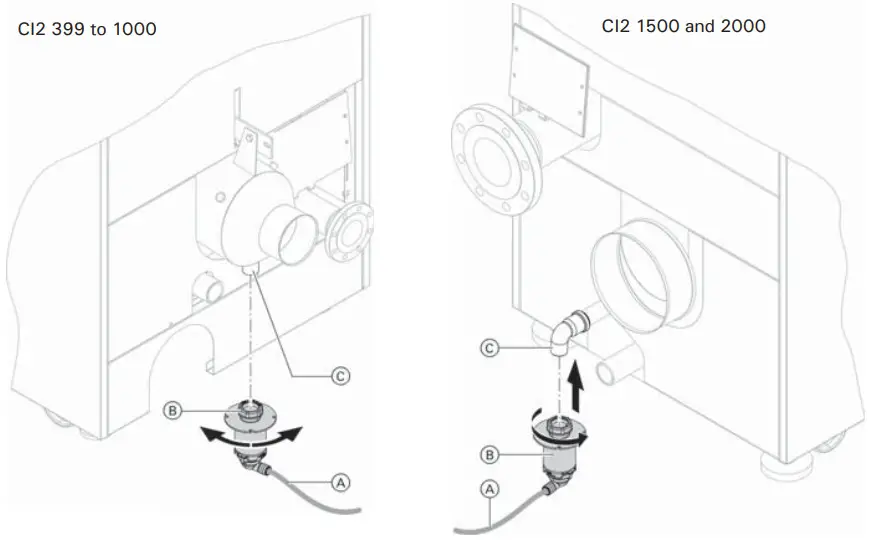
Legend
A Condensate drain connection
B Condensate trap
C Drain line
Connecting the Neutralization System
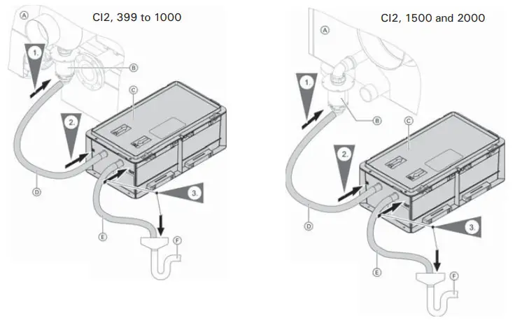
Legend
A Vitocrossal 200 CI2
B Condensate trap
C Neutralizing system (accessories)
D Condensate trap hose (included with the boiler) to neutralizing system
E Drain hose
F Drain (on-site)
Making the Fuel Gas Connections
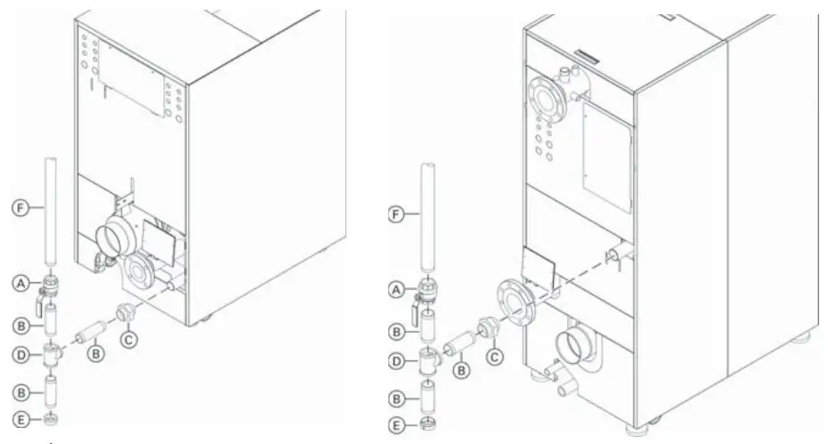
Legend
A Manual gas shutoff valve (supplied)
B Nipple (field supplied)
C Ground joint union (recommended) (field supplied)
D Tee (field supplied)
E Cap (field supplied)
F On site gas line
*1 If using ducted combustion air filter kit on the Vitocrossal 200 CI2 1500 and 2000 ensure to leave min. 16 in. (400 mm) clearance between boiler and drip pocket.
Accessing the DIN Rail
- Remove two screws for junction box access door.
- Rotate junction box access door to remove.
- Select an available knock-out on the rear jacketing of the boiler.
Remove the knock-out and apply a strain relief to the opening. - Route the cable through the strain relief to the DIN rail or Control boards (WP or MZIO), as required.
Boiler Control Locations
Location of the control unit components for CI2 399 to 1000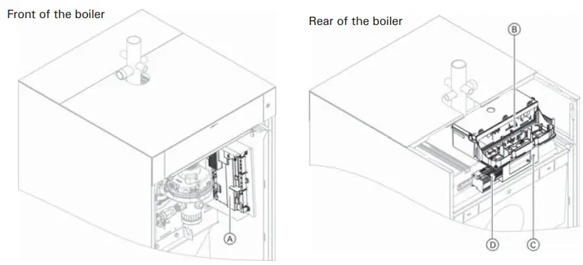
Legend
A BCU
B Control unit with WP and MZIO
C LAN socket
D DIN rail
Location of the control unit components for CI2 1500/2000
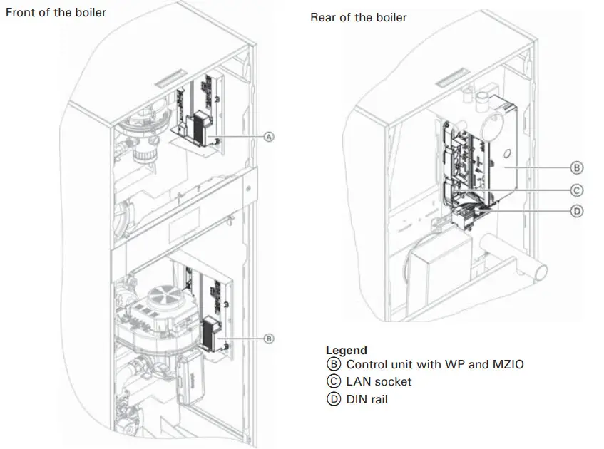
Legend
A Burner control unit 1 (BCU)
B Burner control unit 2 (BCU)
Legend
B Control unit with WP and MZIO
C LAN socket
D DIN rail
Making the Vent Connection
Legend
A Flue vent collar coupling (supplied with boiler)
B Approved venting (field supplied)
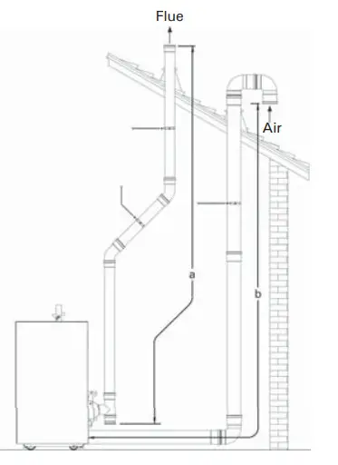
Two pipe – vertical exhaust/vertical intake
a – Equivalent exhaust length
b – Equivalent air intake length
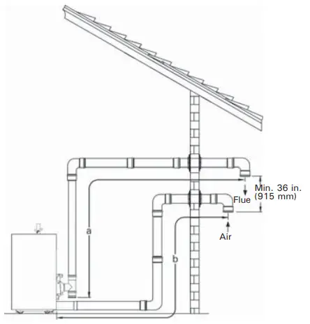
Two pipe – horizontal exhaust/horizontal intake
a – Equivalent exhaust length
b – Equivalent air intake length
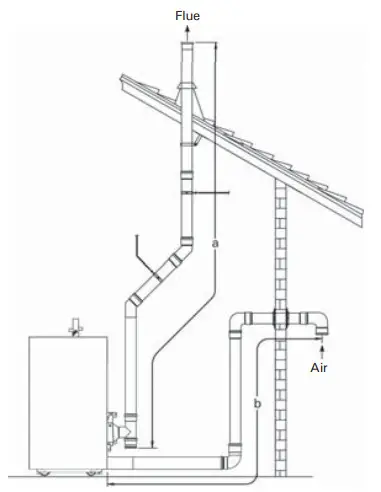
Two pipe – vertical exhaust/ horizontal intake
a – Equivalent exhaust length
b – Equivalent air intake length
Vertical intake and exhaust
| Vrtocrossal 200 Cl2 Boiler model | 399 | 500 | 750 | 1000 | 1500 | 2000 |
| Boiler flue collar (internal diameter) in. (mm) | 4 (104.2) | 4 (104.2) | 6 (155) | 6 (155) | 6 (155) | 8 (205.2) |
| Combustion air intake diameter in. (mm) | 4 (104.2) | 4 (104.2) | 6 (155) | 6 (155) | 6 (155) | 8 (205.2) |
| Max. total equivalent length (a +b) ft. (m) | 198 (60) | 198 (60) | 198 (60) | 198 (60) | 198 (60) | 198 (60) |
Starting the Boiler Using the Commissioning Assistant
| Commissioning assistant sequence | Explanations and references | |
| Commissioning | ||
| Language | Factory setting: English | |
| With programming unit | If commissioning is to be carried out at the programming unit of the boiler. | |
| With software tool | The boiler automatically switches on the WiFi access point. Further commissioning steps according to the instructions of the software tool used (e.g. “Viguide”) Cascade systems can only be commissioned using the software tool. | |
| Units of measurement | ||
| Date and time | Set the current time. | |
| Operating mode | Weather-compensated operation The outside temperature sensor must be connected. Constant operation Operation with constant supply temperature | |
| Gas type | If operating with LPG, switch to “LPG” (the delivered condition is Natural Gas) | |
| Flue system type | Single connection Only one boiler is connected to the flue system (factory setting). Multiple connections Several boilers are connected to the flue system (common venting). | |
| Flue length adjustment | Specification of the effective flue and ventilation air length. To determine the effective flue and ventilation air length, see page 43, chapter “Matching the burner output to the flue system”. | |
If no further settings are to be performed, the commissioning assistant can now be closed.
| Commissioning assistant sequence | Explanations and references | |
| System scheme | ||
| Heating circuit 1 | Heating circuit without mixing valve | |
| Heating circuit 2, 3 … | Heating circuits with mixing valve | |
| DHW ■ Not available ■ Tank with one sensor ■ Tank with one sensor and DHW recirculation pump ■ Tank with temperature switch ■ Tank with temperature switch and DHW recirculation pump | Settings for DHW heating according to the system components System without DHW heating System with DHW tank with 1 tank temperature sensor System with DHW tank with 1 DHW tank temperature sensor and DHW recirculation pump System with DHW tank with temperature switch (such as an aquastat) System with DHW tank with temperature switch, (such as an aquastat) and DHW recirculation pump | |
| Low loss header/buffer tank ■ Not available ■ Low loss header, heating only ■ DHW heating upstream of low loss header ■ DHW heating downstream of low loss header ■ Buffer tank, heating only ■ DHW heating upstream of buffer tank ■ DHW heating downstream of buffer tank | Settings for the consumer circuits according to the system components There is no low loss header or heating water buffer tank in the system. System with low loss header, without DHW heating DHW heating with e.g. separate DHW tank connected upstream of the low loss header DHW heating with e.g. separate DHW tank connected downstream of the low loss header System with heating water buffer tank, without DHW heating DHW heating with e.g. separate DHW tank connected upstream of the heating water buffer tank DHW heating with e.g. separate DHW tank connected downstream of the heating water buffer tank | |
| Heating zone/safety input ■ Heating zone 1 ■ Heating zone 2 ■ Heating zone 3 (based on boiler application type) | Not available, or temperature controller or safety input 1 Not available or temperature controller Or safety input 2 Not available or temperature controller Or safety input 3 | |
| Commissioning assistant sequence | Explanations and references | |
| Floating contact: Function selection plug 96 | If a contact has been connected to plug 96. | |
| ■ No function ■ External demand, DHW circulation pump ■ External demand (based on boiler application type) ■ External blocking ■ Heat demand (based on boiler application type) | Push button function, DHW recirculation pump runs for 5 min. Boiler demand with adjustable target supply temperature (parameter 528.0) and target primary pump speed (parameter 1100.2) Call for heat is shown in the display/menu as “Heating zone 4”. | |
| EM-EA1 (based (D10): Function selection on boiler application type) | If an EM-EA1 extension (DIO electronics module) is connected as a function extension. | |
| Functions | Selection of the connected function according to the table in the EM-EA1 extension installation instructions. | |
| Remote control units | ||
| (based on boiler application type) | Set the type of remote control and subscriber no. as assignment to the respective heating circuit. Up to 4 heating circuits can be assigned to one remote control unit. It is not possible for several remote controls to act on one heating circuit. | |
| “Primary pump” | ||
| ■ No pump ■ Boiler circuit pump ■ Boiler circuit pump | On/off control 0 – 10V modulation control | |
| Maintenance | ||
| Interval in burner hours run until next maintenance | Interval adjustable in steps of 100 h. | |
| Interval until next maintenance | Interval adjustable to 3, 6, 12, 18 or 24 months. | |
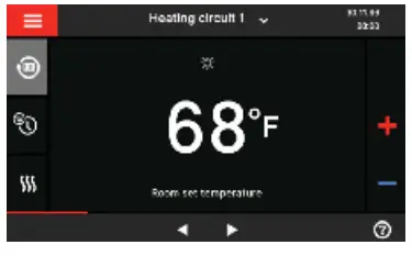
Setting the Room Temperature
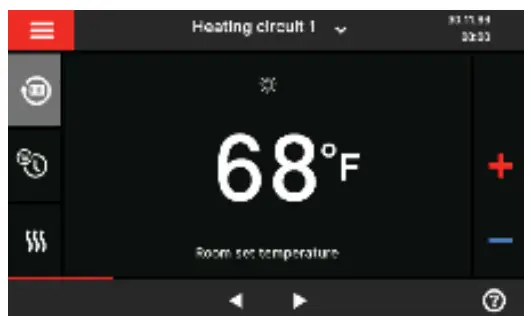
- Tap the header bar and select desired heating circuit.
- Tap
 .
. - Tap for either reduced, standard, or comfort to adjust temperature set point.
 to confirm, this will take you back to the home screen.
Adjusting the Heating Curve
In the delivered condition, the slope of the heating curve is set to 1.4, the level of the heating curve is set to 0.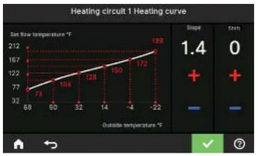
Typical Radiant = 0.6 slope & 0 curve set point
Typical Baseboard = 2.4 slope & 0 curve set point
Typical Fan Coil = 0.8 slope & 15 curve set point
By setting the “Heating curve”, you influence the supply temperature provided by the boiler.
To ensure your rooms are heated optimally at any outside temperature, you can adjust the “Shift” and “Slope” of the “Heating curve”.
Factory setting:
“Slope”: 1.4
“Shift”: 0
Tap the following buttons:

 “Heating”
- Select “heating zone or heating circuit”.
- Select a heating zone or heating circuit, e.g.
 “Heating circuit 1”
 - “Heating curve”
- for the required value for “Slope” and “Shift” respectively.
The graph displayed clearly shows the change in the “Heating curve” as soon as you alter the value for the “Slope” or“Shift”.
Setting DHW Temperature
Tap the following buttons:
- If applicable,◀▶ for the “DHW” default display
- for the required value
 to confirm
Note: Not valid for systems with a DHW tank with temperature switch (e.g. Aquastat).
The factory settings 122°F (50°C).
Note: For reasons of good hygiene, you should not set the DHW temperature lower than 122°F (50°C).
Scan for digital copy of this document
 Viessmann Manufacturing Company (U.S.) Inc. 45 Access Road Warwick, Rhode Island
02886
USA TechInfo Line 1.844-649-5886 1-800-288-0667* Fax (401) 732-0590
www.viessmann-us.com
[email protected]


