VIESSMANN Vitodens B2HA/B2HB Gas Boiler
Safety
Safety, Installation and Warranty Requirements
Please ensure that these instructions are read and understood before commencing installation. Failure to comply with the instructions listed below and details printed in this manual can cause product/property damage, severe personal injury, and/or loss of life. Ensure all requirements below are understood and fulfilled (including detailed information found in manual subsections).
- Licensed professional heating contractor
The installation, adjustment, service and maintenance of this equipment must be performed by a licensed professional heating contractor.- Please see section entitled “Important Regulatory and Installation Requirements” in the Installation Instructions.
- Product documentation
Read all applicable documentation before commencing installation. Store documentation near boiler in a readily accessible location for reference in the future by service personnel.- For a listing of applicable literature, please see section entitled “Important Regulatory and Safety Requirements” in the Installation Instructions.
- Carbon monoxide
Improper installation, adjustment, service and/or maintenance can cause flue products to flow into living space. Flue products contain poisonous carbon monoxide gas.- For information pertaining to the proper installation, adjustment, service and maintenance of this equipment to avoid formation of carbon monoxide, please read these Installation Instructions carefully
- Equipment venting
Never operate boiler without an installed venting system. An improper venting system can cause carbon monoxide poisoning. - Warranty
Information contained in this and related product documentation must be read and followed. Failure to do so renders the warranty null and void. - Advice to owner
Once the installation work is complete, the heating contractor must familiarize the system operator/ ultimate owner with all equipment, as well as safety precautions/requirements, shutdown procedure, and the need for professional service annually before the heating season begins. - Approvals
Viessmann boilers, burners and controls are approved for sale in North America by CSA International. - Codes
The installation of this unit shall be in accordance with local codes. In the absence of local codes, use:- CSA C22.1 Part 1 and/or local codes in Canada
- National Electrical Code ANSI/NFPA 70 in the U.S.
Always use latest editions of codes. The heating contractor must comply with the Standard for Controls and Safety Devices for Automatically Fired Boilers, ANSI/ASME CSD-1 where required by the authority having jurisdiction.
- Working on the equipment
The installation, adjustment, service, and maintenance of this product must be done by a licensed professional heating contractor who is qualified and experienced in the installation, service, and maintenance of hot water boilers. There are no user serviceable parts on the boiler, burner, or control. - Power supply
Install power supply in accordance with the regulations of the authorities having jurisdiction or, in absence of such requirements, in accordance with National Codes. Viessmann recommends the installation of a disconnect switch to the 120V power supply outside of the boiler room. Ensure main power supply to equipment, the heating system, and all external controls have been deactivated. Close main oil or gas supply valve. Take precautions in both instances to avoid accidental activation of power during service work.- Please carefully read this manual prior to attempting installation. Any warranty is null and void if these instructions are not followed. For information regarding other Viessmann System Technology componentry, please reference documentation of the respective product. We offer frequent installation and service seminars to familiarize our partners with our products. Please inquire.
- The completeness and functionality of field supplied electrical controls and components must be verified by the heating contractor. These include low water cut-offs, flow switches (if used), staging controls, pumps, motorized valves, air vents, thermostats, etc.
Excerpt from 248 CMR 5-08:
- INSTALLATION OF CARBON MONOXIDE DETECTORS. At the time of installation of the side-wall horizontal vented gas fueled equipment, the installing plumber or gas fitter shall observe that a hard wired carbon monoxide detector with an alarm and battery back-up is installed on the floor level where the gas equipment is to be installed. In addition, the installing plumber or gas fitter shall observe that a battery operated or hard wired carbon monoxide detector with an alarm is installed on each additional level of the dwelling, building or structure served by the side-wall horizontal vented gas fueled equipment. It shall be the responsibility of the property owner to secure the services of qualified licensed professional for the installation of hard-wired carbon monoxide detectors.
- a. In the event that the side-wall horizontally vented gas fueled equipment is installed in a crawl space or an attic, the hard-wired carbon monoxide detector with alarm and battery back-up may be installed on the next adjacent floor level.
- b. In the event that the requirements of this subdivision can not be met at the time of completion of installation, the owner shall have a period of thirty (30) days to comply with the above requirements; provided, however, that during said thirty (30) day period, a battery operated carbon monoxide detector with an alarm shall be installed.
- APPROVED CARBON MONOXIDE DETECTORS. Each carbon monoxide detector as required in accordance with the above provisions shall comply with NFPA 720 and be ANSI/UL 2034 listed and IAS certified.
- SIGNAGE. A metal or plastic identification plate shall be permanently mounted to the exterior of the building at a minimum height of eight (8) feet above grade directly in line with the exhaust vent terminal for the horizontally vented gas fueled heating appliance or equipment. The sign shall read, in print size no less than one-half (b) inch in size, “GAS VENT DIRECTLY BELOW. KEEP CLEAR OF ALL OBSTRUCTIONS”.
- INSPECTION. The state or local gas inspector of the side-wall horizontally vented gas fueled equipment shall not approve the installation unless, upon inspection, the inspector observes carbon monoxide detectors and signage installed in accordance with the provisions of 248 CMR 5.08(2)(a) 1 through 4.
About these Installation Instructions
Take note of all symbols and notations intended to draw attention to potential hazards or important product information.
- Indicates an imminently hazardous situation which, if not avoided, could result in death, serious injury or substantial product/property damage.
- Indicates an imminently hazardous situation which, if not avoided, may result in minor injury or product / property damage.
- Helpful hints for installation, operation or maintenance which pertain to the product.
- This symbol indicates to note additional information
- This symbol indicates that other instructions must be referenced.
Venting
General Venting Information
Installation steps (outline)
WARNING: Ensure that the entire venting system is protected from physical damages. A damaged venting system may cause unsafe conditions.
IMPORTANT
Boiler operation in marine environments (damp, salty coastal areas):
The service life of the boiler’s exposed metallic surfaces, such as the casing and fan housing, is directly influenced by proximity to damp and salty marine environments. In such areas, higher concentration levels of chlorides from sea spray, coupled with relative humidity, can lead to degradation of the exposed metallic surfaces mentioned above. Therefore, it is imperative that boilers installed in such environments not be installed using direct vent systems which draw outdoor air for combustion. Such boilers must be installed using room air dependent vent systems; i.e. using room air for combustion. The indoor air will have a much lower relative humidity and, hence, the corrosion will be minimized.
- Route vent pipe as directly as possible and with as few bends as possible to the boiler.
- Check proper location of gaskets in rigid PP pipe collars. (Only use supplied parts with the polypropylene venting system.) Apply water to lubricate the joint ends of the vent pipe collar and if used, the air intake pipe collar.
- Slide pipes into each other with a gentle twisting motion.
- Condensate must drain from the flue pipe to the boiler. Ensure a suitable gradient of at least 3º [approx. 2 in. per 3.3 ft. (50 mm per 1 m)].
- Use a hacksaw or sheet metal snips (for stainless steel) to cut pipes to length (if necessary). Use a file to smooth rough edges. Pipe must be round and not bent into an oval shape.
IMPORTANT: When cutting pipes to length, debur and clean pipes.
- For stainless steel and PP venting systems: In conjunction with these instructions, follow the installation instructions supplied by the special venting manufacturer.
Combustion air intake, flex hose and adaptor must be installed. If using room air-independent venting system, connect the air intake pipe (from outdoors)to the adaptor provided. If room air-dependent venting system is used, the air is drawn into the burner inlet through boiler adaptor.
Recommended venting practice
When installing a venting system the following recommended venting practices apply:
- Keep length and number of 90º elbows to a minimum.
- Try not to use back-to-back 90º elbows.
- Use 45º elbows where possible to minimize the number of 90º elbows in case redirection of flue gas is required.
- The special vent system shall not be routed into, through, or within any other vent such as an existing masonry or factory-built chimney.
Exception:
A masonry chimney flue may be used to route the venting system only if no other appliance is vented in the same flue.
Approved venting materials
Approved materials for two-pipe system
| Part | Material | Certified to Standards | Applicability |
| Exhaust pipe and fitting | Stainless steel | UL1738 “Venting systems for gas-burning appliances, Categories II, III, IV” | U.S.A./Canada |
| ULC S636 “Standard for Type BH gas venting systems” | |||
| CPVC | UL1738 “Venting systems for gas-burning appliances, Categories II, III, IV” | ||
| ULC S636 “Standard for Type BH gas venting systems” Class IIB 90°C | |||
| Polypropylene PP(s) | UL1738 “Venting systems for gas-burning appliances, Categories II, III, IV” | ||
| ULC S636 “Standard for Type BH gas venting systems” Class IIC 110°C | |||
| Combustion air pipe and fitting | Stainless steel | No applicable standards | |
| Galvanized steel | Suitable for outdoor use | ||
| PVC-DWV Schedule 40 | ANSI/ASTM D2661 CSA B181.1 ULC S102.2 ANSI/ASTM D2665, D1785 CSA B137.3, B181.2 ANSI/ASTM F441 | ||
| CPVC Schedule 40 | ANSI/ASTM D2661 CSA B181.1 ULC S102.2 ANSI/ASTM D2665, D1785 CSA B137.3, B181.2 ANSI/ASTM F441 | ||
| ABS-DWV Schedule 40 | ANSI/ASTM D2661 CSA B181.1 ULC S102.2 ANSI/ASTM D2665, D1785 CSA B137.3, B181.2 ANSI/ASTM F441 | ||
| Polypropylene PP(s) | UL1738 “Venting systems for gas-burning appliances, Categories II, III, IV” | ||
| ULC S636 “Standard for Type BH gas venting systems” Class IIC 110°C | |||
| Pipe cement, primer (for combustion air intake pipe) | PVC | ANSI/ASTM D2564 CSA B137.3 | |
| CPVC | ANSI/ASTM F493 CSA B137.6 | ||
| ABS | ANSI/ASTM D2235 CSA B181.1/B182.1 | ||
| Pipe cement, primer (for exhaust pipe and fitting) | CPVC | ULC S636 “Standard for Type BH gas venting systems” Class IIB 90°C |
Note: Venting systems may combine two different approved venting materials, provided that all venting materials and all required transition adaptors are supplied by one venting manufacturer. Always use latest edition of applicable standard.
Flashing and storm collar installation
Flashings and storm collars are field supplied. Flashings and storm collars suitable for Type B vent materials (or better) may be used. To obtain flashings and storm collars, please contact your local vent material supplier. Follow the installation instructions supplied by the special venting manufacturer. Follow local codes to properly isolate the exhaust vent pipe when passing through floors, ceiling and roof. Always check the marking on the pipe to make sure you are using the correct material. Contact one of the suppliers (see listing on right) to order the vent system. Prior to installation, check that the correct single-wall vent parts were ordered and supplied. Exhaust vent/air intake connection to boiler The vent connection to the Vitodens boiler must be made with the starter stainless steel adaptor when using stainless steel (supplied by others).
IMPORTANT: For exhaust vent pipe material: Do not use any other vent material.
Vent System Suppliers
Use special venting system (UL/ULC listed for Category IV) for exhaust vent material of the Vitodens boilers (contact one of the venting suppliers).
| M&G / Duravent Web: www.duravent.com | ICC – Industrial Chimney Co. |
| Selkirk Canada Corporation | Novaflex |
| Centrotherm InnoFlue | Van-Packer Co. Inc. |
| Security Chimneys International Ltd. | Enervex Inc. (formerly Exhausto) Web:www.enervex.com |
Requirement for UL/ULC Listed Rigid SS/PP(s) Vent Pipe Material
The venting system must be installed by a licensed professional heating contractor familiar with the operation and maintenance of heating appliances and venting. Before installing, ensure that the complete installation literature has been read. Failure to follow proper installation procedures as stated in these instructions, including vent pitch and proper appliance connections, may violate local, provincial/state, or national codes and cause unsafe conditions which may lead to severe property damage or personal injury. The venting system must be installed in accordance with local building code requirements as well as national codes. For installations in Canada use CAN/CSA-B149.1 Natural Gas Installation Code or CAN/CSA-B149.2
Propane Installation Code as applicable; in the U.S. use the National Fuel Gas Code ANSI Z223.1 or NFPA Standard 54. Always use latest edition of applicable standard. To ensure safe operation of the appliance, Viessmann recommends that the system be inspected once a year by a qualified service technician. Every venting system must be planned and installed for optimum performance and safety. These Installation Instructions are designed to help you determine venting requirements and limitations with respect to installation. Please read and follow these instructions carefully. It is the responsibility of the installer to contact local building and fire officials concerning any installation restrictions and/or inspection requirements that may apply. Permits may be required before commencement of the installation.
The air intake termination ( if installed on a side wall) should be located on a wall that is least affected by prevailing winds. High winds may affect boiler operation. If wind is a problem, steps must be taken to shield the air intake termination from high winds, such as building a fence or planting shrubs. Ensure that the total equivalent vent length is not exceeded. Because of its sealed combustion chamber, the Vitodens 200 gas-fired condensing boiler is suitable for operation with balanced flue (when using air intake system). Use only material listed in table on page 7, entitled “Approved venting materials”. This PP vent system is constructed from flame-retardant plastic [polypropylene rated for a maximum temperature of 230ºF (110ºC)]. The PP venting system components must be listed to ULC S636 / UL-1738 (contact one of the venting suppliers see page 8). DO NOT mix pipe, fittings, or joining methods from different vent system manufacturers. The vent length requirements stated in this manual on page 12 must be observed. If using flexible venting system, reduce the maximum equivalent length allowed by 25%.
Vent Requirements
Combustion air supply, room air dependent application only
This boiler requires fresh air for safe operation and must be installed in a mechanical room where there are provisions for adequate combustion and ventilation air. Provisions for combustion and ventilation air must be made in accordance with CAN/CSA-B149.1 or .2 Natural Gas Installation Codes (for installations in Canada) or in accordance with sections for Combustion and Ventilation Air, of the National Fuel Gas Code, ANSI Z223.1 or applicable provisions of local codes (for installations in the U.S.A.) Always use latest edition of applicable standard.
Follow local codes to properly isolate the vent pipe when passing through floors, ceilings and roof. Whenever possible, install boiler near an outside wall so that it is easy to duct fresh air directly to the boiler area. Refer to national codes for duct sizing. Round ducts may be used. The boiler must be vented and supplied with combustion air and exhaust vents as described in this section. Ensure the vent and combustion air supply comply with these instructions.
WARNING: Failure to provide an adequate supply of fresh combustion air can cause poisonous flue gases to enter living space, which can cause severe personal injury or loss of life.
The boiler location should never be under negative pressure. Exhaust fans, attic fans, or dryer fans may cause air to be exhausted at a rate higher than the air can enter the structure for safe combustion. Corrective action must be taken to ensure enough air is available. Never cover the boiler or store debris or other materials near the boiler, or in any way block the flow of adequate fresh combustion air to the boiler. If boiler is installed in a confined space (a space with a volume of less than 50 cubic feet per 1000 Btu/h of gas input for all fuel burning equipment) or building layout is unusually tight, adequate air for combustion must be provided by two openings: one located about 6 in. below the ceiling, the other about 6 in. above the floor. When communicating directly with the outside, each opening must have a minimum free area of one square inch per 2000 Btu/h of gas input. When all combustion air is provided by openings in doors, etc. to adjoining spaces having adequate infiltration, each opening must have a minimum free area of one square inch per 1000 Btu/h of gas input, but not less than 100 in2. You must know the free area of louvers used to cover up the combustion and ventilation openings in closet installations. If you do not know the free area, assume 20% for wood louvers and 60-75% free area for metal louvers. When using louvers, the openings have to be made larger. For example, a free 14 in. x 6 in. (356 mm x 152 mm) opening becomes a 14 in. x 10 in. (356 mm x 254 mm) opening for a grill containing metal louvers.
Installation
Boiler Layout
General
- Only the Vitodens 200 boilers B2HA 45, 60, 80, 88, 100, 112, 150, 285, 311, 352, 399, 530 and B2HB 45, 57, 160, 199 can be connected to a common vent (header).
- The Vitodens 200 boilers connected to the common vent must all be of the same size.
- A maximum of 4 boilers can be vented to a common venting system.
- A maximum of 4 boilers can be connected to a common air intake.
- Flue gas backflow is prevented by the integrated flue gas damper (see page 30).
Wall mounted boilers
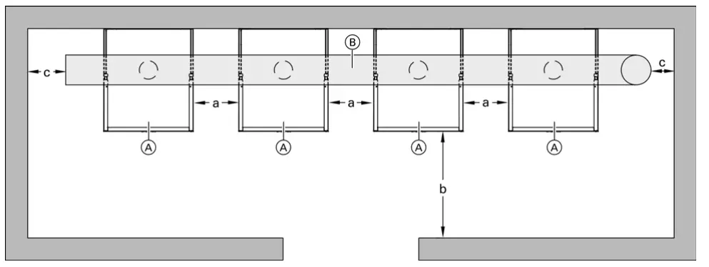
Legend
- A Boiler
- B Flue gas common venting system
Service Clearance Dimensions
| a | 1 in. (25 mm) minimum |
| b | 28 in. (710 mm) |
| c | 12 in. (305 mm) |
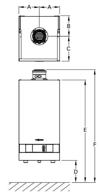
Boiler Dimensions
| B2HA 45, 60 in. (mm) | B2HB 45, 57, 160, 199 in. (mm) | B2HA 80, 88, 100, 285, 311, 352 in. (mm) | B2HA 112, 150, 399, 530 in. (mm) | ||||
| A | 9b | (240) | 9b | (240) | 9b | (240) | 11c (300) |
| B | 6a | (160) | 6a | (160) | 9a | (236) | 11 (278) |
| C | 8c | (220) | 14b | (220) | 11c | (294) | 16 (411) |
| D | 40c | (1031) | 40c | (1031) | 405/8 (1031) | 38c (982) | |
| E | 777/8 | (1975) | 777/8 | (1975) | 77c | (1975) | 78c (1975) |
| F | 80a | (2036) | 80a | (2036) | 83d | (2110) | 83d (2110) |
Boilers mounted on a distribution manifold:
Legend
- A Boiler
- B Flue gas common venting system
Service Clearance Dimensions:
| a | 1 in. (25 mm) minimum |
| b | 28 in. (710 mm) |
| c | 12 in. (305 mm) |
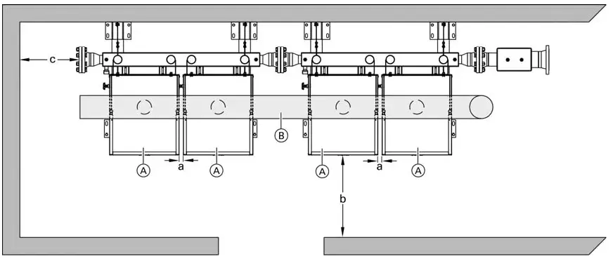
Boilers mounted on a back to back distribution manifold:
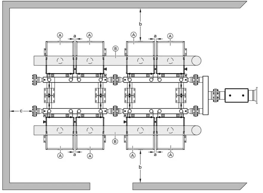
Legend
- A Boiler
- B Flue gas common venting system
Service Clearance Dimensions:
| a | 1 in. (25 mm) minimum |
| b | 28 in. (710 mm) |
| c | 12 in. (305 mm) |
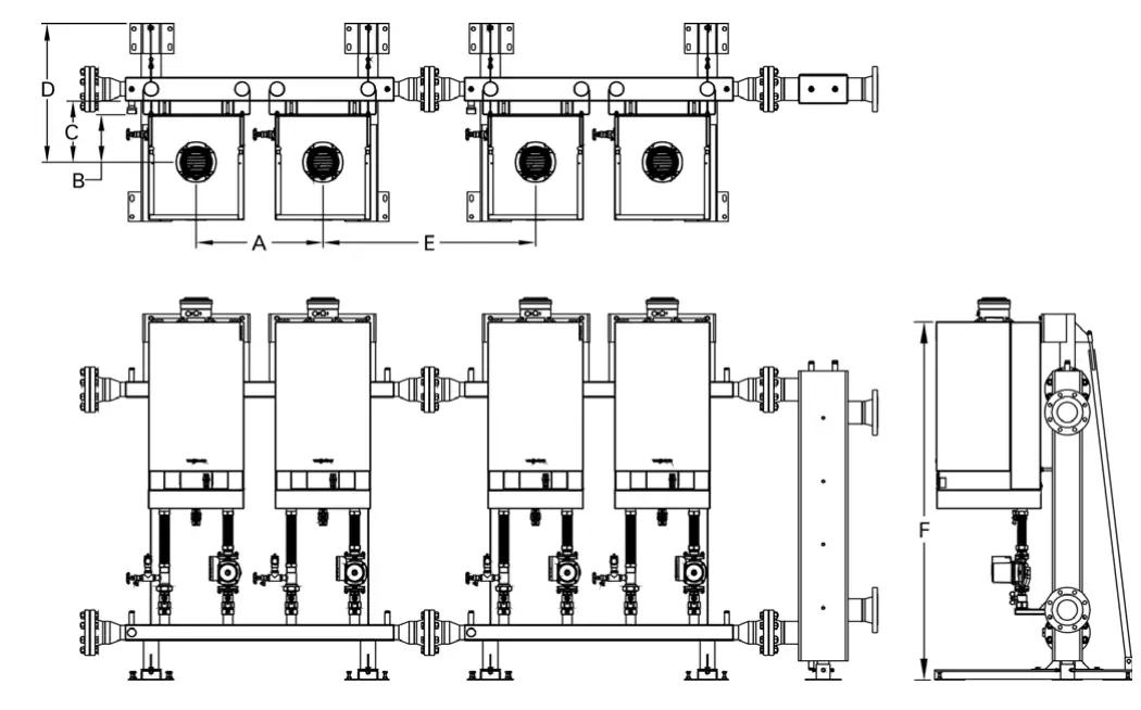
2 Boiler Manifold Dimensions
Note: Example shown is the B2HA 80, 88, 100, 285, 311, 352
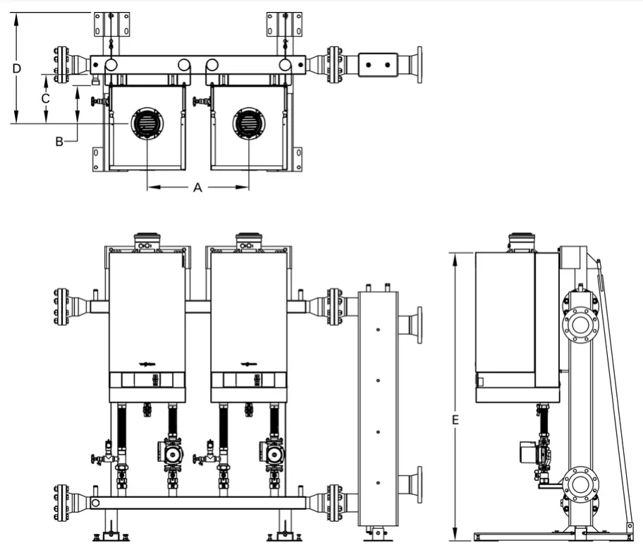
| Boiler model # | B2HA 45, 60 | B2HB 45, 57, 160, 199 | B2HA 80, 88, 100, 285, 311, 352 | B2HA 112, 150, 399, 530 | |
| A | in. (mm) | 25a (640) | 25a (640) | 25a (640) | 25a (640) |
| B | in. (mm) | 6a (159) | 6a (159) | 9e (240) | 11 (281) |
| C | in. (mm) | 9 (229) | 9 (229) | 12a (310) | 13c (351) |
| D | in. (mm) | 24e (619) | 24e (619) | 27f (700) | 29a (741) |
| E | in. (mm) | 73 (1857) | 73a (1864) | 76 (1933) | 75b (1920) |
3 Boiler Manifold Dimensions
Note: Example shown is the B2HA 80, 88, 100, 285, 311, 352
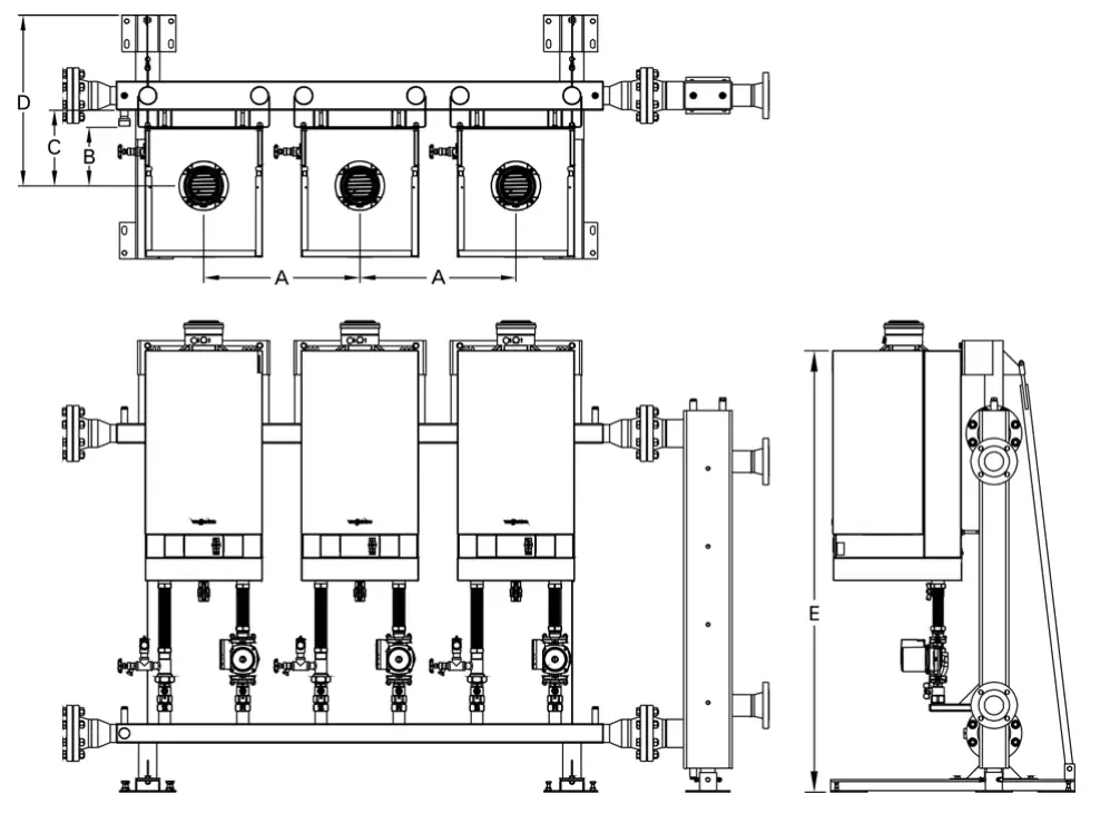
| Boiler model # | B2HA 45, 60 | B2HB 45, 57, 160, 199 | B2HA 80, 88, 100, 285, 311, 352 | B2HA 112, 150, 399, 530 | |
| A | in. (mm) | 25a (640) | 25a (640) | 25a (640) | 25a (640) |
| B | in. (mm) | 6a (159) | 6a (159) | 9e (240) | 11 (281) |
| C | in. (mm) | 9 (229) | 9 (229) | 12a (310) | 13c (351) |
| D | in. (mm) | 24e (619) | 24e (619) | 27f (700) | 29a (741) |
| E | in. (mm) | 73 (1857) | 73a (1864) | 76 (1933) | 75b (1920) |
4 Boiler Manifold Dimensions (Linear)
Note: Example shown is the B2HA 80, 88, 100, 285, 311, 352
| Boiler model # | B2HA 45, 60 | B2HB 45, 57, 160, 199 | B2HA 80, 88, 100, 285, 311, 352 | B2HA 112, 150, 399, 530 | |
| A | in. (mm) | 25a (640) | 25a (640) | 25a (640) | 25a (640) |
| B | in. (mm) | 6a (159) | 6a (159) | 9e (240) | 11 (281) |
| C | in. (mm) | 9 (229) | 9 (229) | 12a (310) | 13c (351) |
| D | in. (mm) | 24e (619) | 24e (619) | 27f (700) | 29a (741) |
| E | in. (mm) | 42a (1073) | 42a (1073) | 42a (1073) | 42a (1073) |
| F | in. (mm) | 73 (1857) | 73a (1864) | 76 (1933) | 75b (1920) |
4 Boiler Manifold Dimensions (Back-to-Back)
Note: Example shown is the B2HA 80, 88, 100, 285, 311, 352
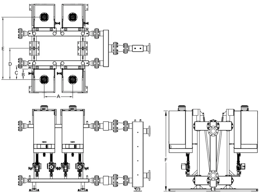
| Boiler model # | B2HA 45, 60 | B2HB 45, 57, 160, 199 | B2HA 80, 88, 100, 285, 311, 352 | B2HA 112, 150, 399, 530 | |
| A | in. (mm) | 25a (640) | 25a (640) | 25a (640) | 25a (640) |
| B | in. (mm) | 6a (159) | 6a (159) | 9e (240) | 11 (281) |
| C | in. (mm) | 9 (229) | 9 (229) | 12a (310) | 13c (351) |
| D | in. (mm) | 24e (619) | 24e (619) | 27f (700) | 29a (741) |
| E | in. (mm) | 49d (1073) | 49d (1073) | 55b (1410) | 58c (1491) |
| F | in. (mm) | 73 (1857) | 73a (1864) | 76 (1933) | 75b (1920) |
Venting Layout
General
- Sidewall venting is NOT allowed, only vertical vent (room air dependant or independent), positive pressure cat. IV can be used when common venting.
- The maximum equivalent length of the venting system must not exceed the values specified in the charts starting on page 22.
- Available pressure at the flue outlet is 100 pa. (0.40 “w.c.). Pressure available at the outlet of the boiler flue collar can be used to calculate a revised vent system by the vent manufacturer (if needed).
IMPORTANT
- The manufacturer’s vent flue gas back flow preventers are not required and must not be installed due to the integrated flue gas flapper (refer to page 29).
- If the venting layout configurations described in these instructions are changed (e.g. including additional components) it is the responsibility of the venting manufacturer to recalculate the vent diameter. DO NOT reduce venting diameters listed.
- The boiler flue connection is not designed to support the weight of the vent system connected to the boiler. Contact the vent manufacturer for proper support. See list of manufacturers on page 8.
- Condensate must drain from the flue pipe to the boiler. Ensure a suitable gradient of at least 3º [approx. 2 in. per 3.3 ft. (50 mm per 1 m)] on any horizontal venting components.
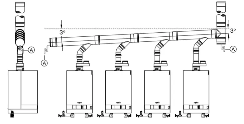
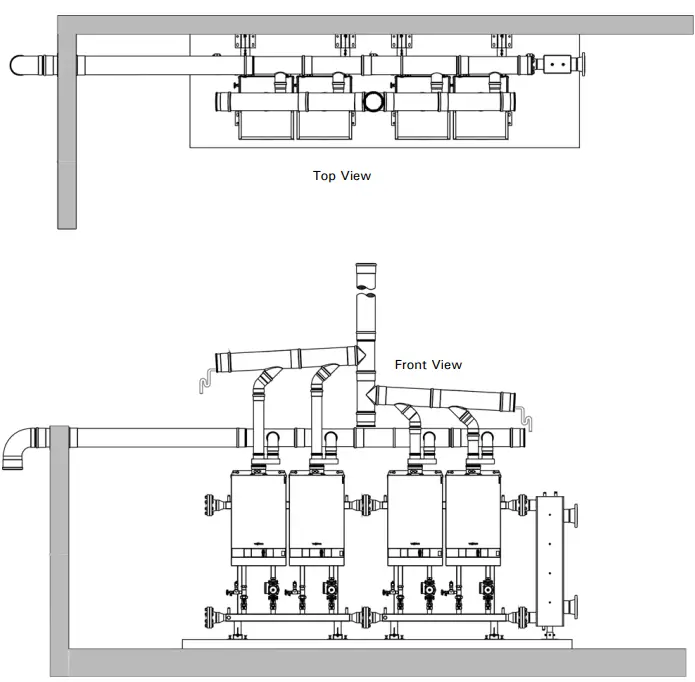
Legend
- A Condensate drain piping
- B Individual feed elbow(s)
- C Header elbow
- D Base tee
Exclude the header elbow C and base tee D from the equivalent vent length calculation.
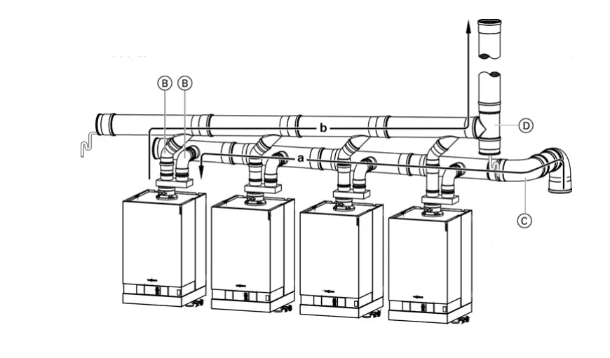
Note: Maximum equivalent vent lengths for the combustion air intake (a) and the flue gas venting (b) are calculated separately. Refer to the charts starting on page 22 for maximum equivalent lengths.
Common Flue with Room Air Dependant Combustion Air Intake
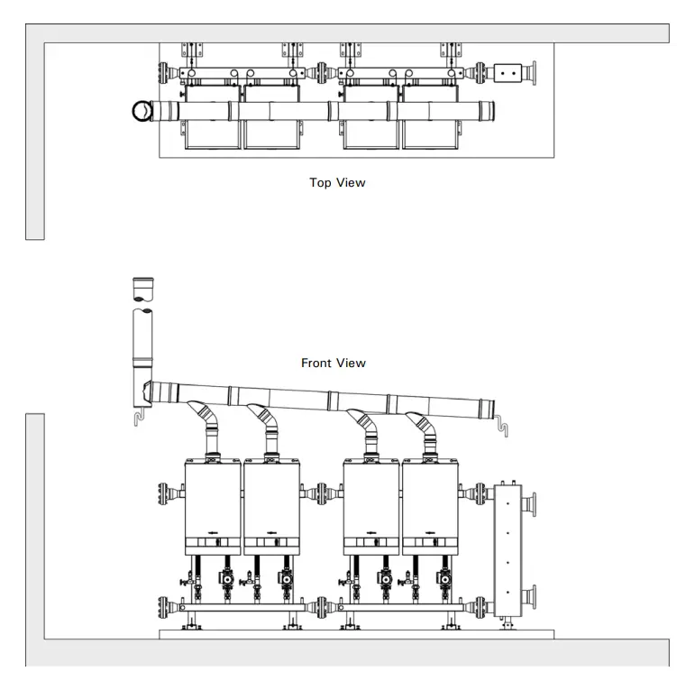
Note: This is a generic layout for illustration purposes only. Please contact the vent manufacturer for a project-specific venting layout.
Common Flue with Room Air Independant Combustion Air Intake
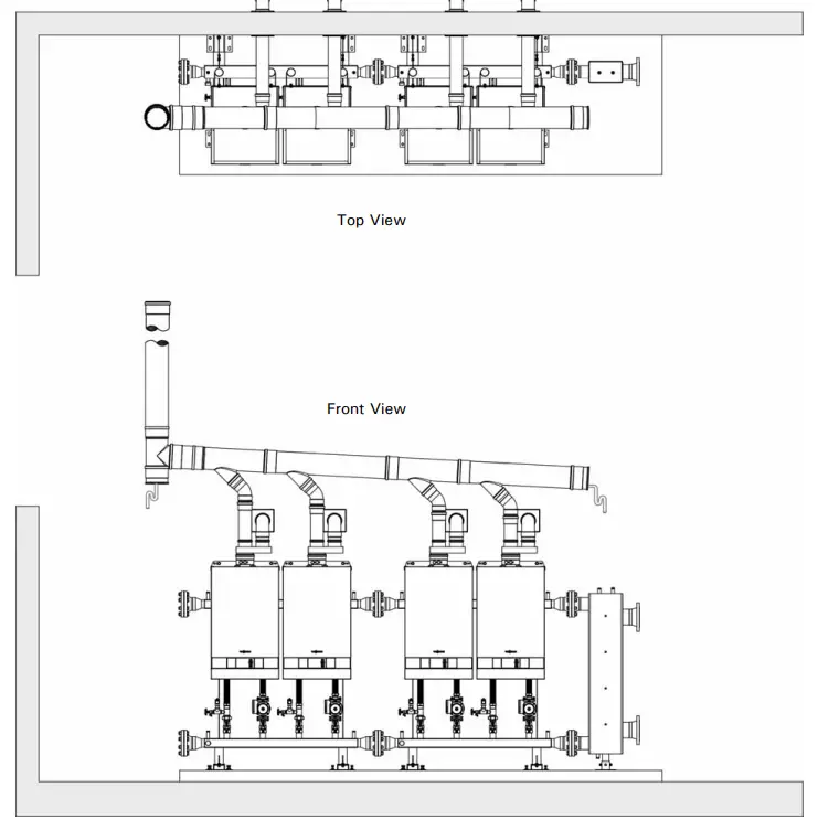
Note: This is a generic layout for illustration purposes only. Please contact the vent manufacturer for a project specific venting layout.
Common Flue with Common Combustion Air Intake
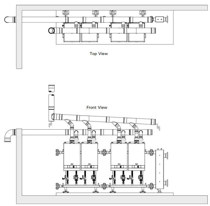
Note: This is a generic layout for illustration purposes only. Please contact the vent manufacturer for a project specific venting layout.
Note: This is a generic layout for illustration purposes only. Please contact the vent manufacturer for a project specific venting layout.
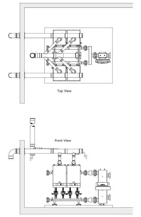
Split Common Flue with Common Combustion Air Intake
Note: This is a generic layout for illustration purposes only. Please contact the vent manufacturer for a project specific venting layout.
Independant Combustion Air/Common Flue Vent Dimensions
Venting System for Vitodens 200 B2HA 45, 60, B2HB 45, 57, 160, 199
- Diameter
Common vertical flue in. (mm) 6 (150) Common horizontal flue in. (mm) 6 (150) Combustion air intake in. (mm) 4 (100) - Maximum equivalent length
2 Boilers Flue ft. (m) 100 (30) Combustion air intake (per boiler) ft. (m) 33 (10) 3 Boilers Flue ft. (m) 100 (30) Combustion air intake (per boiler) ft. (m) 33 (10) 4 Boilers Flue ft. (m) 100 (30) Combustion air intake (per boiler) ft. (m) 33 (10)
Venting System for Vitodens 200 B2HA 80, 88, 100, 285, 311, 352
- Diameter
Common vertical flue in (mm) 6 (150) 8 (200) Common horizontal flue in. (mm) 6 (150) 6 (150) Combustion air intake in.(mm) 4 (100) 4 (100) - Maximum equivalent length
2 Boilers Flue ft. (m) 100 (30) — Combustion air intake (per boiler) ft. (m) 33 (10) — 3 Boilers Flue ft. (m) 100 (30) — Combustion air intake (per boiler) ft. (m) 33 (10) — 4 Boilers Flue ft. (m) 33 (10) 100 (30) Combustion air intake (per boiler) ft. (m) 33 (10) 33 (10)
Venting System for Vitodens 200 B2HA 112, 150, 399, 530
- Diameter
Common vertical flue in. (mm) 8 (200) 8 (200) 12 (300) Common horizontal flue in. (mm) 6 (150) 8 (200) 10 (250) Combustion air intake in. (mm) 4 (100) 4 (100) 4 (100) - Maximum equivalent length
2 Boilers Flue ft. (m) 100 (30) — — Combustion air intake (per boiler) ft. (m) 33 (10) — — 3 Boilers Flue ft. (m) 86 (26) 100 (30) — Combustion air intake (per boiler) ft. (m) 33 (10) 33 (10) — 4 Boilers Flue ft. (m) N/A N/A 100 (30) Combustion air intake (per boiler) ft. (m) N/A N/A 33 (10)
Note: Only same size and same series boilers can be connected to a common venting system.
Note: Individual feed elbows from the boiler must be included in the equivalent vent length calculation. See page 24 for elbow equivalent lengths. One 90o elbow (or two 45o elbows) and one base tee on the common header are excluded from the equivalent vent length calculation. See page 17 to calculate equivalent vent lengths.
Common Combustion Air/Common Flue Vent Dimensions
Venting System for Vitodens 200 B2HA 45, 60, B2HB 45, 57, 160, 199
- Diameter
- Maximum equivalent length
Venting System for Vitodens 200 B2HA 80, 88, 100, 285, 311, 352
- Diameter
- Maximum equivalent length
Venting System for Vitodens 200 B2HA 112, 150, 399, 530
- Diameter
- Maximum equivalent length
Note: Only same size and same series boilers can be connected to a common venting system.
Note: Individual feed elbows from the boiler must be included in the equivalent vent length calculation. See page 24 for elbow equivalent lengths. One 90o elbow (or two 45o elbows) and one base tee on the common header are excluded from the equivalent vent length calculation. See page 17 to calculate equivalent vent lengths.
Elbow – Equivalent Length
Equivalent Length
| Elbow type | 4 in. (100 mm) | 6 in. (150 mm), 8 in. (200 mm), 10 in. (250 mm), 12 in. (300 mm), 14 in. (350 mm) |
| 45º | 1 ft. (0.3 m) | 5 ft. (1.5 m) |
| 90º | 1.6 ft. (0.5 m) | 10 ft. (3 m) |
Standard Sizes of Boiler Flue Gas Adaptors
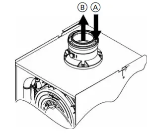
Legend
- A Combustion air
- B Flue gas
Standard sizes of boiler flue gas adaptors
| Boiler model | Adaptor Size |
| B2HA 45 | 80 / 125 |
| B2HB 45, 160 | 80 / 125 |
| B2HB 57, 199 | 80 / 125 |
| B2HA 60 | 80 / 125 |
| B2HA 80, 285 | 110 / 150 |
| B2HA 88, 311 | 110 / 150 |
| B2HA 100, 352 | 110 / 150 |
| B2HA 112, 399 | 110 / 150 |
| B2HA 150, 530 | 110 / 150 |
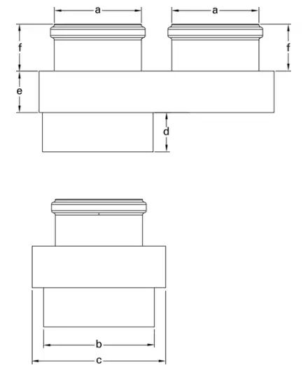
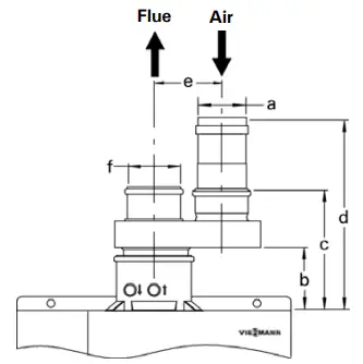
Parallel Pipe Adaptor
| Vitodens B2HA 45, 60 | Vitodens B2HA 80, 88, | |
| Vitodens B2HB 45, 57, | 100, 112, 150, 285, | |
| 160, 199 | 311, 352, 399, 530 | |
| a | 80 mm | 110 mm |
| b | 125 mm | 150 mm |
| c | 6 in. (150 mm) | 6.9 in. (175 mm) |
| d | 2.6 in. (65 mm) | 2.2 in. (52 mm) |
| e | 1.6 in. (37 mm) | 2.2 in. (55 mm) |
| f | 3 in. (73 mm) | 2.7 in. (68 mm) |
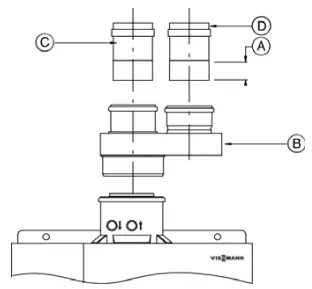
Two Pipe Vent Starter Adaptor
Parallel vent pipe starter adaptors for B2HA 45, 60 and B2HB 45, 57, 160, 199
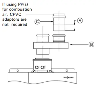
Legend
- A Air intake, max. insertion 2½ in. (64 mm)
- B Viessmann parallel adaptor or Centrotherm parallel adaptor
- C Air intake starter adaptor for PVC, CPVC and ABS only. 80 mm to 3 in. (if using PP(s) for combustion air intake system, an adaptor is not required).
Legend
- a 3 in. (76 mm)
- b 2¾ in. (70 mm)
- c 7 in. (178 mm)
- d approx. 10¾ in. (271 mm)
- e 4¾ in. (120 mm)
- f 80 mm *
For exhaust system Ø of 4 in. (100 mm), an increaser adaptor 3 in. to 4 in. (80 mm to 100 mm) must be used.
Parallel vent pipe starter adaptors for B2HA 80, 88, 100, 112, 150, 285, 311, 352, 399, 530
Legend
- A Air intake, max. insertion 2½ in. (64 mm)
- B Viessmann parallel adaptor
- C PP(s) slip joint transition adaptor (110 mm to 100 mm) only required if M&G system is used
- D Air intake starter adaptor for PVC, CPVC and ABS, when using PP(s) system 110 mm to 100 mm, a transition adaptor is required.
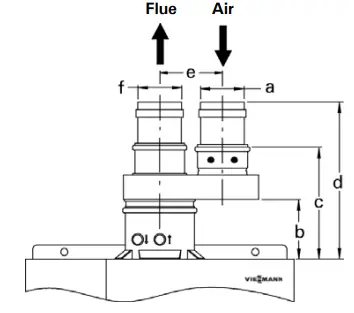
Legend
- a 4 in. (100 mm) with M&G transition adaptor
- b 5d in. (130 mm)
- c 9e in. (237 m)
- d approx. 127/8 in. (327 mm)
- e 5½ in. (140 mm)
- f 4 in. (100 mm) with M&G transition adaptor
Parallel adaptor for two-pipe system:
| Supplier | Boiler Model | Ø in. (mm) | Quantity |
| Viessmann | B2HA 45, 60, B2HB 45, 57, 160, 199 | 3 (80) | 1 |
| B2HA 80, 88, 100, 112, 150, 285, 311, 352, 399, 530 | 4 (110) | 1 |
Vent Termination Location Requirements – Vertical
The vent must be installed observing local regulations in addition to National Codes, CAN/CSA-B149.1 or 2 (for installations in Canada) or ANSI-Z223.1 or NFPA 54 (for installations in the U.S.A.).
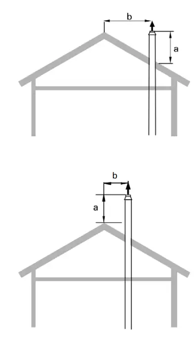
- For sloped roof applications with distance b less than 18 in. (450 mm) a minimum 18 in. (450 mm) b <18 in. (450 mm)
- For sloped roof applications with distance b greater than 18 in. (450 mm)
- For flat roof applications
| Boiler Model | a (min. distance) |
| Vitodens 200-W | 18 in. (450 mm) |
WARNING: Vent termination must be at least 12 in. (300 mm) above the anticipated snow level (consult your local building authorities or local weather office). Locate vent termination in such a way that it cannot be blocked by snow.
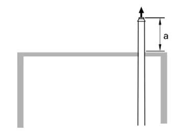
A vent used in a special venting system with positive vent pressure and passing through a roof shall extend at least 18 in. (450 mm) above the highest point where it passes through the roof and any other obstruction within a horizontal distance of 18 in. (450 mm).
The special vent system shall not be routed into, through, or within any other vent such as an existing masonry or factory-built chimney.
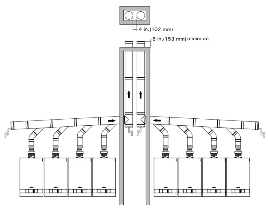
Vent Length Requirements
Multiple boiler installations (vertical termination with multiple boilers) When terminating the vertical vent pipes of multiple Vitodens boilers, a minimum clearance of 4 inches (100 mm) is required between the outside edges of each vent pipe.
Installing Vent Piping
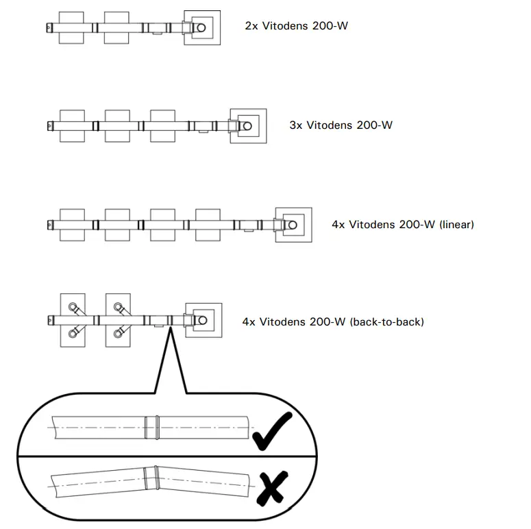
Note: Ensure that venting connections are aligned properly as per the manufacturer’s instructions.
Flue Vent Damper
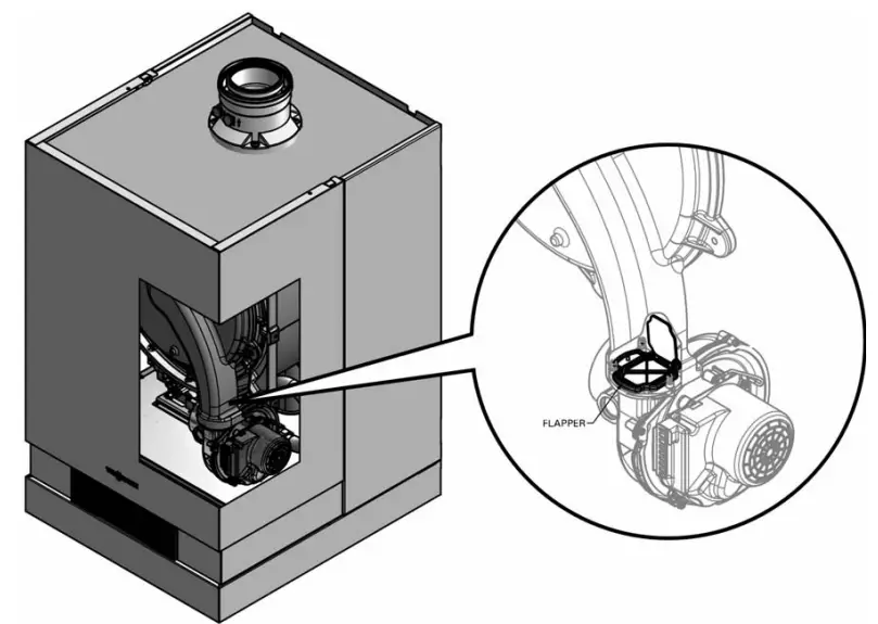
Flue gas flapper operation
The mechanical flue gas flapper is designed to prevent flue gas back flow through the boiler by utilizing burner pressure to open and close the flapper. The flapper is only open during burner operation and closed when the burner is not in operation. This provides an effective seal against back flow to the common venting system.
WARNING: Failure to provide adequate protection against flue has leakage into living space can cause personal injury and and/or loss of life!
This boiler is certified for use in a category IV positive pressure common venting system application. When this boiler is installed as part of a common venting system, performing service work, such as removing the burner and/or heat exchanger assemblies, requires that all other boilers in the common venting system are shut down until the service work has been completed. If the boiler’s burner and/or heat exchanger assembly remains open, the boiler must be disconnected from the common venting system and the boiler flue connection on the common venting system must be sealed to prevent any flue gas leakage into the boiler room.
Componentry (System Options)
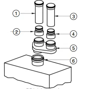
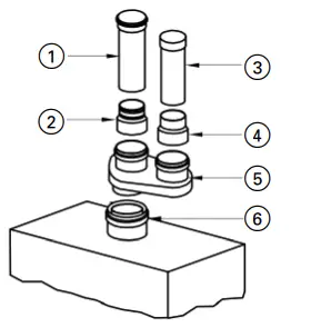
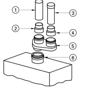
Two Pipe Options B2HA 45, 60, B2HB 45, 57, 160, 199 (Direct Vent)
PP(s) Vent pipe PP(s) Air intake pipe
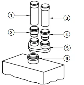
| # | Component | Supplied |
| 1 | Vent Component | Field |
| 2 | Vent increaser (if required) (80 mm to 100 mm) | Field |
| 3 | Air intake component | Field |
| 4 | Air intake increaser (if required) (80 mm to 100 mm) | Field |
| 5 | Double pipe adaptor (80 mm/125 mm to 80 mm and 80 mm) | Viessmann |
| 6 | Boiler coaxial adaptor (80 mm / 125 mm) | C/W Boiler |
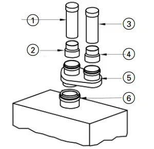
PP(s) Vent pipe CPVC, ABS or PVC Air intake pipe
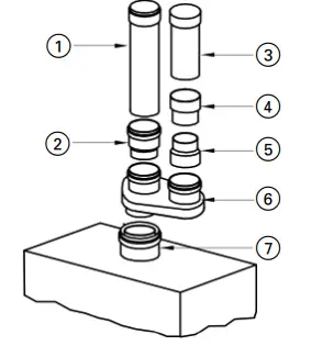
| # | Component | Supplied |
| 1 | Vent Component | Field |
| 2 | Vent increaser (if required) (80 mm to 100 mm) | Field |
| 3 | Air intake component | Field |
| 4 | Air intake increaser (if required) (3 in. to 4 in.) | Field |
| 5 | Air intake adaptor (80 mm to 3 in.) | Viessmann |
| 6 | Double pipe adaptor, (80 mm/125 mm to 80 mm and 80 mm) | Viessmann |
| 7 | Boiler coaxial adaptor (80 mm / 125 mm) | C/W Boiler |
CPVC Vent pipe CPVC, ABS or PVC Air intake pipe
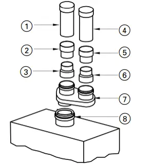
| # | Component | Supplied |
| 1 | Vent Component | Field |
| 2 | Vent increaser (if required) (3 in. to 4 in.) | Field |
| 3 | Vent adaptor, (80 mm to 3 in.) | Viessmann |
| 4 | Air intake component | Field |
| 5 | Air intake increaser (if required) (3 in. to 4 in.) | Field |
| 6 | Air intake adaptor (80 mm to 3 in.) | Viessmann |
| 7 | Double pipe adaptor (80 mm/125 mm to 80 mm and 80 mm) | Viessmann |
| 8 | Boiler coaxial adaptor (80 mm / 125 mm) | C/W Boiler |
Stainless Steel Vent pipe CPVC, ABS or PVC Air intake pipe
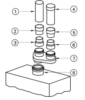
| # | Component | Supplied |
| 1 | Vent Component | Field |
| 2 | Vent increaser (if required) (3 in. to 4 in.) | Field |
| 3 | Vent starter adaptor (SS), (80 mm to 3 in.) | Field |
| 4 | Air intake component | Field |
| 5 | Air intake increaser (if required) (3 in. to 4 in.) | Field |
| 6 | Air intake adaptor (80 mm to 3 in.) | Viessmann |
| 7 | Double pipe adaptor (80 mm/125 mm to 80 mm and 80 mm) | Viessmann |
| 8 | Boiler coaxial adaptor (80 mm / 125 mm) | C/W Boiler |
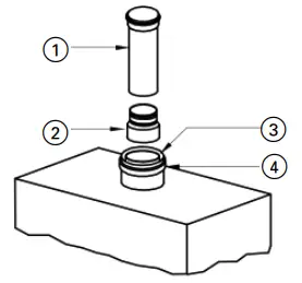
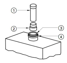
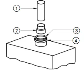
Single Pipe Options B2HA 45, 60, B2HB 45, 57, 160, 199 (Room Air Dependent)
PP(s) Vent pipe
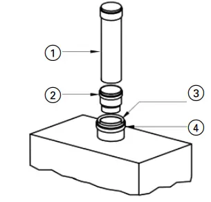
| # | Component | Supplied |
| 1 | Vent Component | Field |
| 2 | Vent increaser (if required) (80 mm to 100 mm) | Field |
| 3 | Combustion air inlet (location) | |
| 4 | Boiler coaxial adaptor (80 m / 125 mm) | C/W Boiler |
CPVC Vent pipe
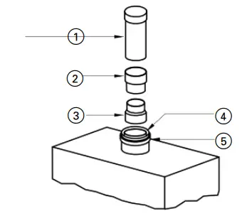
| # | Component | Supplied |
| 1 | Vent Component | Field |
| 2 | Vent increaser (if required) (3 in. to 4 in.) | Field |
| 3 | Vent adaptor, (80 mm to 3 in.) | Viessmann |
| 4 | Combustion air inlet (location) | |
| 5 | Boiler coaxial adaptor (80 mm / 125 mm) | C/W Boiler |
Stainless Steel Vent pipe
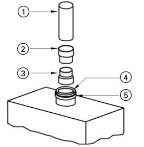
| # | Component | Supplied |
| 1 | Vent Component | Field |
| 2 | Vent increaser (if required) (3 in. to 4 in.) | Field |
| 3 | Vent starter adaptor (SS), (80 mm to 3 in.) | Field |
| 4 | Combustion air inlet (location) | |
| 5 | Boiler coaxial adaptor (80 mm / 125 mm) | C/W Boiler |
Two Pipe Options B2HA 80 to 530 (Direct Vent)
PP(s) Vent pipe PP(s) Air intake pipe
| # | Component | Supplied |
| 1 | Vent Component | Field |
| 2 | Vent starter adaptor, (110 mm to 100*) | Field |
| 3 | Air intake component | Field |
| 4 | Air intake starter adaptor, (110 mm to 100) | Field |
| 5 | Double pipe adaptor (110 mm/150 mm to 110 mm and 110 mm) | Viessmann |
| 6 | Boiler coaxial adaptor (110 mm / 150 mm) | C/W Boiler |
PP(s) Vent pipe CPVC, ABS or PVC Air intake pipe
| # | Component | Supplied |
| 1 | Vent Component | Field |
| 2 | Vent starter adaptor, (110 mm to 100*) | Field |
| 3 | Air intake component | Field |
| 4 | Air intake starter adaptor, (110 mm to 4 in.) | Viessmann |
| 5 | Double pipe adaptor (110 mm/150 mm to 110 mm and 110 mm) | Viessmann |
| 6 | Boiler coaxial adaptor (110 mm / 150 mm) | C/W Boiler |
CPVC Vent pipe CPVC, ABS or PVC Air intake pipe
| # | Component | Supplied |
| 1 | Vent Component | Field |
| 2 | Vent starter adaptor, (110 mm to 4 in.) | Viessmann |
| 3 | Air intake component | Field |
| 4 | Air intake starter adaptor, (110 mm to 4 in.) | Viessmann |
| 5 | Double pipe adaptor (110 mm/150 mm to 110 mm and 110 mm) | Viessmann |
| 6 | Boiler coaxial adaptor (110 mm / 150 mm) | C/W Boiler |
Stainless Steel Vent pipe CPVC, ABS or PVC Air intake pipe
| # | Component | Supplied |
| 1 | Vent Component | Field |
| 2 | Vent starter adaptor (SS), (110 mm to 4 in.) | Field |
| 3 | Air intake component | Field |
| 4 | Air intake starter adaptor, (110 mm to 4 in.) | Viessmann |
| 5 | Double pipe adaptor (110 mm/150 mm to 110 mm and 110 mm) | Viessmann |
| 6 | Boiler coaxial adaptor (110 mm / 150 mm) | C/W Boiler |
Single Pipe Options B2HA 80 to 530 (Room Air Dependent)
PP(s) Vent pipe
| # | Component | Supplied |
| 1 | Vent Component | Field |
| 2 | Vent starter adaptor (110 mm to 100*) | Field |
| 3 | Combustion air inlet (location) | |
| 4 | Boiler coaxial adaptor (110 mm / 150 mm) | C/W Boiler |
CPVC Vent pipe
| # | Component | Supplied |
| 1 | Vent Component | Field |
| 2 | Vent starter adaptor (110 mm to 4 in.) | Viessmann |
| 3 | Combustion air inlet (location) | |
| 4 | Boiler coaxial adaptor (110 mm / 150 mm) | C/W Boiler |
Stainless Steel Vent pipe
| # | Component | Supplied |
| 1 | Vent Component | Field |
| 2 | Vent starter adaptor (SS), (110 mm to 4 in.) | Field |
| 3 | Combustion air inlet (location) | |
| 4 | Boiler coaxial adaptor (110 mm / 150 mm) | C/W Boiler |
Viessmann Manutacturing Company Inc.
750 McMurray Road
Waterloo, Ontario N2V 2G5 Canada
Techlnfo Line 1-888-484-8643
1-800-387-7373 Fax (519) 885-0887
www.viessmann.ca [email protected]
Viessmann Manufacturing Company (U.S.) Inc.
45 Access Road
Warwick, Rhode Island 02886 USA
Techinfo Line 1-888-484-8643
1-800-288-0667 Fax (401) 732-0590
www.viessmann-us.com [email protected]


