InVid Tech Solar Surveillance System
Installation Manual Solar Surveill ance System
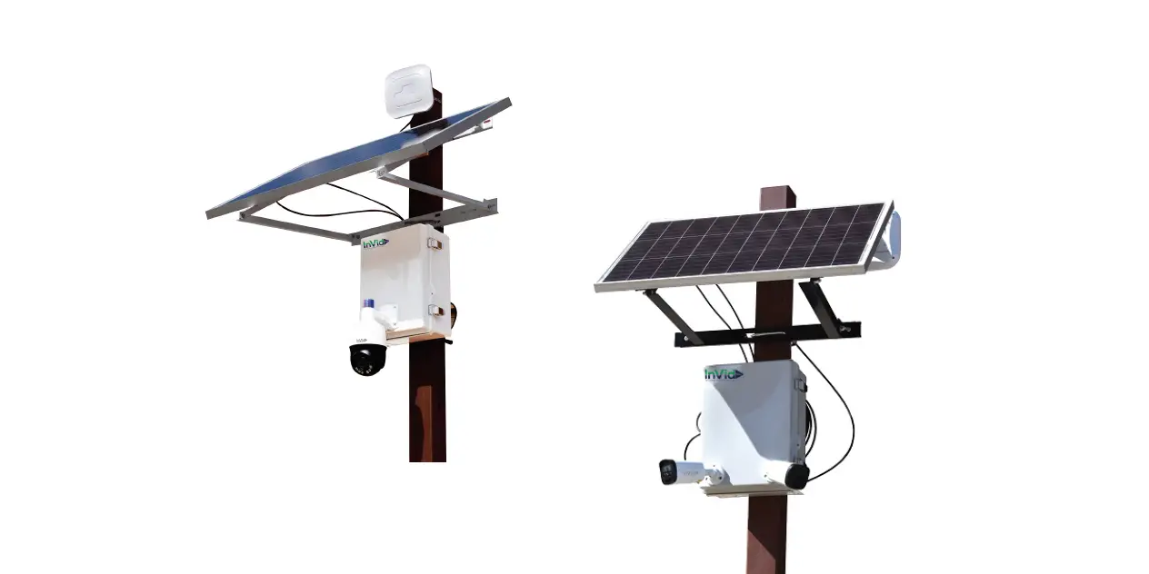
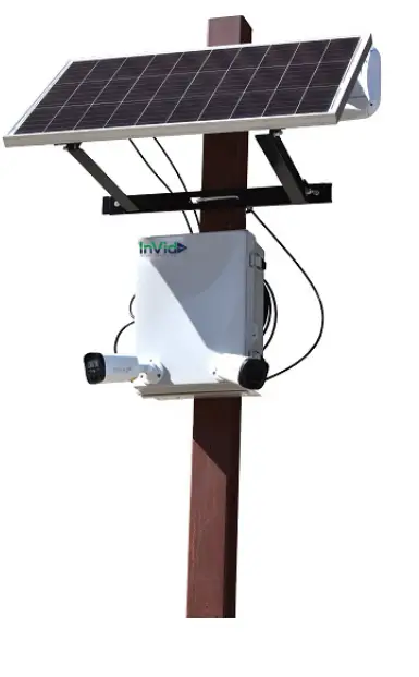
The Solar Surveillance System is a self-contained security system that is powered by solar energy. It includes a camera, a solar panel, a battery, and a wireless communication module. The system is designed to be mounted on a pole or post and can be used in remote locations where there is no access to power.
Installation Manual Table of Contents
- Mounting Kit Assembly
- Securing Mounting Kit to Pole/ Post
- Securing Solar Panel to Mounting Kit
- Enclosure Mounting Information
- MC4/ RJ45 (Network Cable) Connection Instructions
- Solar Charger Controller Information
- LED Light Signal Interpretation Chart
- LED Flash Rhythm Chart
- LCD Display Interface and Overview
- LCD Status Information
- Key Functionality Chart
- LCD Display Rules and Cycles
- Setting Battery Mode
- Error Code Chart
- Pont-to-Point Connections and Settings
- DIP Device Configuration
- Camera Configuration Setup Figure
- Signal Power Setting
- Troubleshooting an FAQ
- 4G Router Setup Guide
- How to Set Up Cameras for the Solar Surveillance System
Mounting Kit Assembly
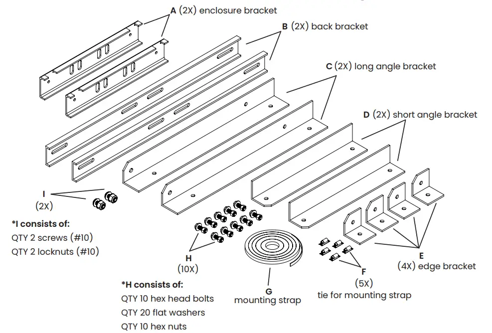
The mounting kit assembly consists of various brackets, bolts, and straps that are used to mount the solar panel and enclosure onto a pole or post.
Follow the steps below to assemble the mounting kit:
- Align edge brackets (Item E) with the outside slots on the back bracket (Item B) and secure using hex bolts, two washers, and a hex nut (Items H). Attach QTY 2 edge brackets to each back bracket.
- Using the remaining hex bolts, flat washers, and hex nuts, attach the long and small angle brackets (Items C and D) to the back brackets.
Securing Mounting Kit to Pole/ Post
Follow the steps below to secure the mounting kit assembly to the desired pole or post:
- Using the mounting straps and ties for the mounting straps, secure the mounting kit assembly to the desired pole or post. The suggested diameter pole (or length and width of a post) to use for mounting is between 2 and 6 inches.
- U-bolts may be used as an alternate mounting method but are not provided.
Securing Solar Panel to Mounting Kit
Follow the steps below to secure the solar panel to the mounting kit:
- Insert hex bolts with washer through the holes on the top-side of the long angle bracket and tighten down the solar panel.
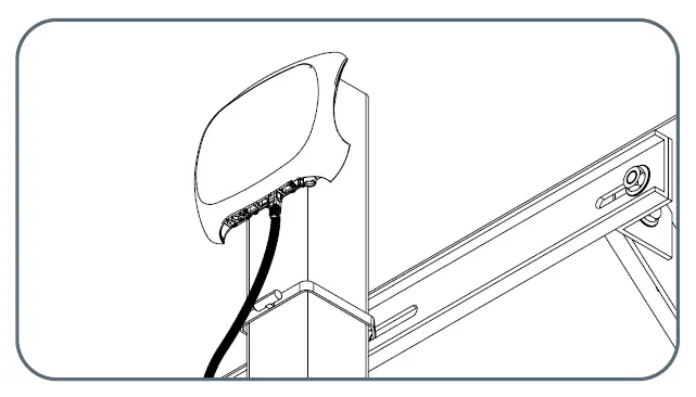
Enclosure Mounting Information
Follow the steps below to mount the enclosure onto the pole or post:
- Attach enclosure brackets (Item A) to pole/ post using mounting straps and ties for mounting straps (Item G and F).
- Slide the enclosure onto enclosure brackets. Then, using QTY 2 Item I (#10 screws [with QTY 2 #10 locknuts]) secure the enclosure to the bottom enclosure bracket.
MC4/ RJ45 (Network Cable) Connection Instructions
Follow the steps below to connect the network cable:
- Connect to the solar panel using the two cables extruding from the surveillance enclosure with MC4 connectors at the end. See above for reference on what an MC4 connector is.
- To connect: Push the MC4 male connector into the MC4 female connector until there is a click. Connection is only possible one way.
Mounting Kit Assembly
Step 1
Align edge brackets (Item E) with the outside slots on the back bracket (Item B) and secure using hex bolts, two washers, and a hex nut (Items H). Attach QTY 2 edge brackets to each back bracket. 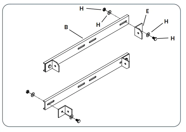
Step 2
Using the remaining hex bolts, flat washers, and hex nuts, attach the long and small angle brackets (Items C and D) to the back brackets as shown in the view to the right. 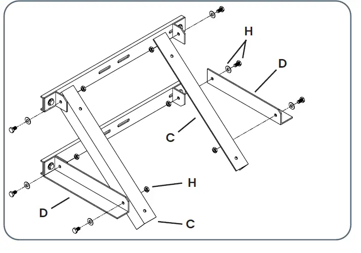
Securing Mounting Kit to Pole/ Post 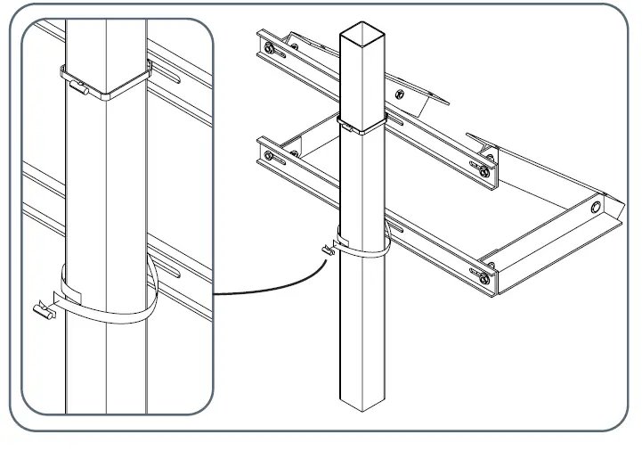
Step 1
Using the mounting straps and ties for the mounting straps, secure the mounting kit assembly to the desired pole/ post.
NOTE: the suggested diameter pole (or length and width of a post) to use for mounting is between 2 and 6 inches.
NOTE: U-bolts may be used as an alternate mounting method but are not provided.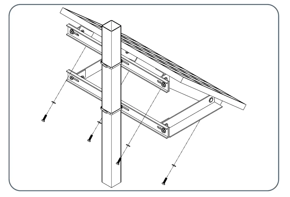
Securing Solar Panel to Mounting Kit
Step 1
Insert hex bolts with washer through the holes on the top-side of the long angle bracket and tighten down the solar panel. 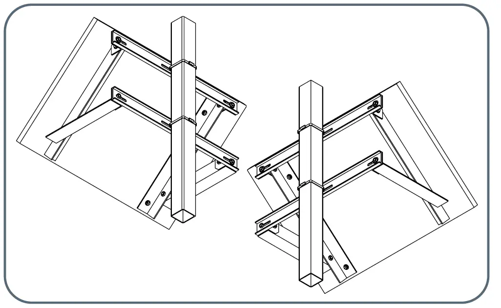
Step 1
Attach enclosure brackets (Item A) to pole/ post using mounting straps and ties for mounting straps (Item G and F).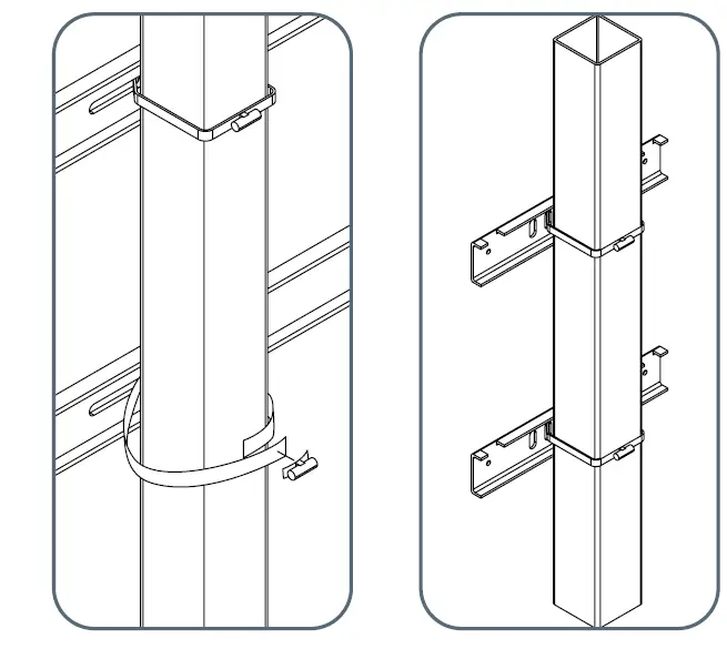
Mounting detail: Cut mounting straps to desired length, slip on tie, and feed other end of mounting strap through. Tighten down until secure.
Step 2
Slide the enclosure onto enclosure brackets as shown in the leftmost view. Then, using QTY 2 Item I (#10 screws [with QTY 2 #10 locknuts]) secure the enclosure to the bottom enclosure bracket. See detailed views A and B below for further detail. 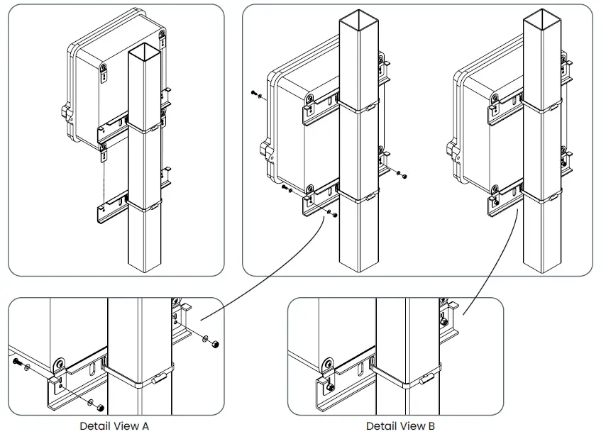
MC4/ RJ45 (Network Cable) Connection Instructions
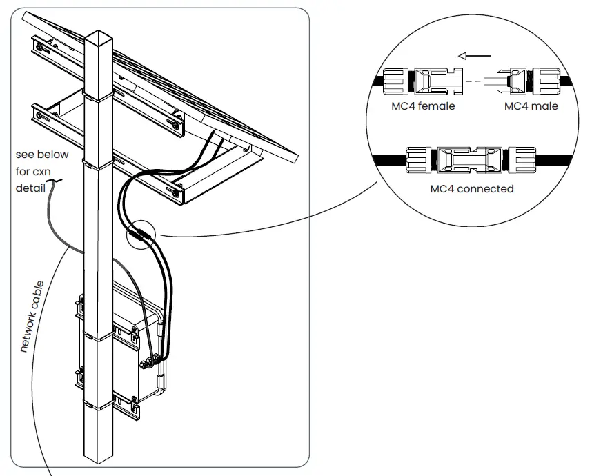
Connect to the solar panel using the two cables extruding from the surveillance enclosure with MC4 connectors at the end. See above for reference on what an MC4 connector is.
To connect:
Push the MC4 male connector into the MC4 female connector until there is a click. Connection is only possible one way.  Example of 4G router connection. RJ45 cable routes directly to 4G router.
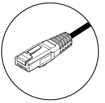 RJ45 Connector (used for P2P or 4G router connections)
 Example of a P2P connection.
RJ45 cable routes directly to camera.
Solar Charger Controller Information
LED Light Signal Interpretation Chart
| LED Name | LED Display | LED Name |
|
PV | off | solar input not charging *PV LED is generally off during nighttime. |
| double flash | solar input charge detected | |
| single flash | solar input reverse polarity | |
| steady on | MPPT charge mode | |
| slow flash | in equalize/ boost/ float charge | |
| BATTERY | single flash | battery input reverse polarity |
| fast flash | battery over voltage | |
| slow flash | battery over discharged | |
| steady on | battery on | |
| LOAD | off | no DC load connected/ load off |
| fast flash | DC load short circuit | |
| steady on | DC load on | |
| FAULT | off | no errors |
| steady on | system error—check error code |
LED Flash Rhythm Chart
| Flash Status | Indication | Description |
| steady on | on off | LED light on |
| off | on off | LED light off |
| fast flash | on off | LED light blinks twice every second (2Hz) |
| slow flash | on off | LED light blinks once every two seconds (0.5Hz) |
| single flash | on off | LED light blinks for 0.1 second every 2 seconds |
| double flash | on off | LED light blinks for 0.1 second every 4 seconds |


LCD Display Interface and Overview
| Display Section | Display Layout |
| charge status |  |
| charge mode & parameter | 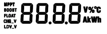 |
| active functions | 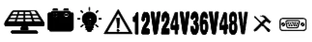 |
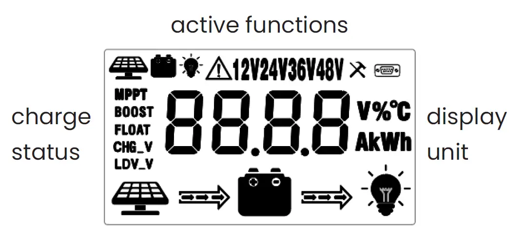 LCD Status Information
| Status Icon | Indication | Status | Description |
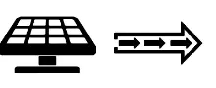 | solar charge indication | flowing | solar power charging battery |
| off | solar power not charging battery | ||
 | DC load indication | flowing | DC load drawing power |
| off | DC load off | ||
| MPPT | charge mode | steady on | MPPT charge mode |
| BOOST | boost charge mode | ||
| FLOAT | float charge mode | ||
| off | not charging | ||
| CHG_V | voltage setting | on | setting charge voltage |
| off | charge boltage has been set | ||
| LDV_V | over discharge volt settings | on | setting discharge voltage |
| off | discharge voltage has been set | ||
 | solar icon | steady on | daylight detected |
| off | no daylight detected | ||
| fast flash | solar system over voltage | ||
 | battery icon | steady on | battery connected and functional |
| off | no battery connection | ||
| fast flash | battery over-discharged | ||
 | load status | flash | DC load short circuit or over-load |
| on | load on | ||
| off | load off |
Key Functionality Chart
| Function Key | System Mode | Input | Input Function |
 | view mode | short press | enter SET mode |
 | view mode | short press | view previous page |
 | view mode | short press | view next page |
 | view mode | short press | DC load on/ off |
| Function Key | System Mode | Input | Input Function |
| set mode | long press | save data & exit SET mode |
| short press | next setting | ||
| set mode | short press | increase parameter value |
| set mode | short press | decrease parameter value |
| set mode | short press | exit SET mode without saving |
LCD Display Rules and Cycles
Pre start-up display cycle when the MPPT controller turns on. Normally, this lasts several seconds while the controller detects the operating environment.
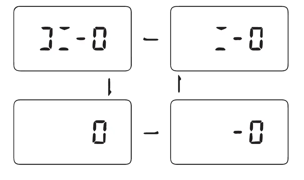
LCD Screen Display Cycle
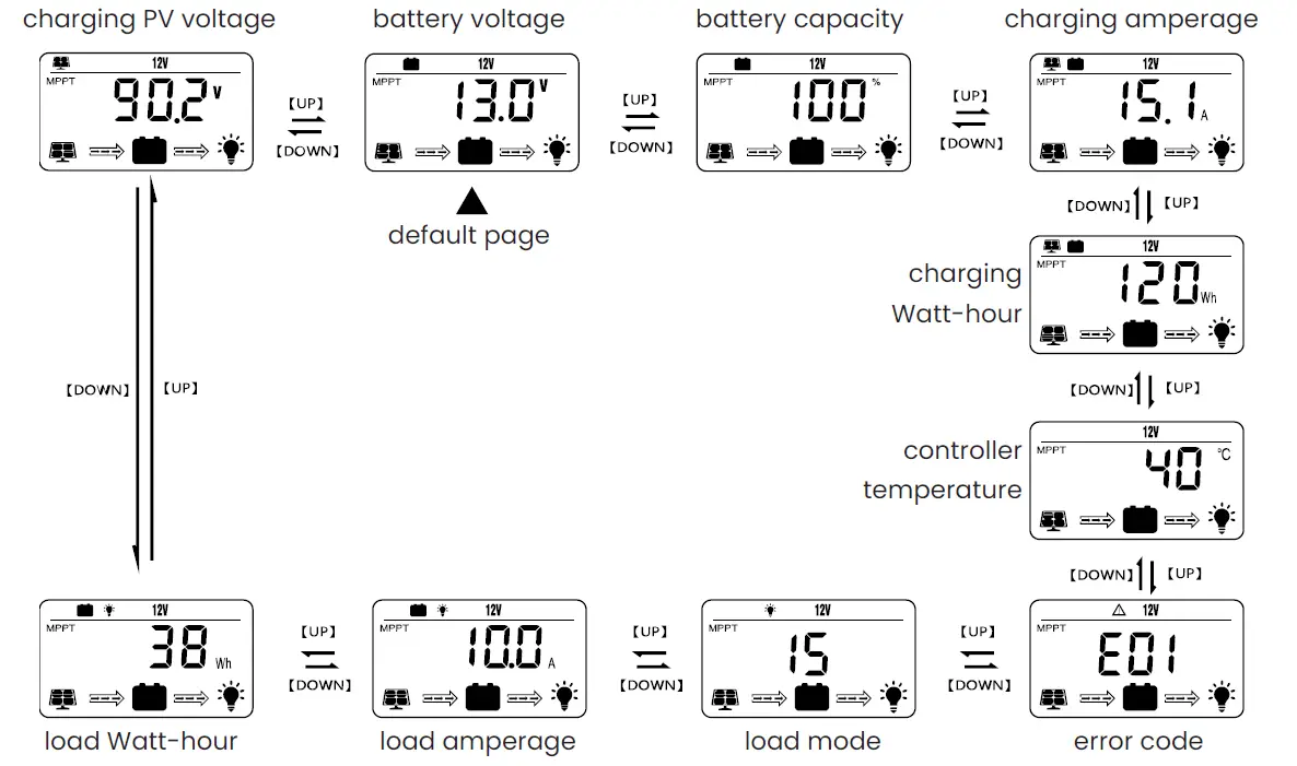
NOTE:
The battery voltage view will be displayed by default. Use the UP and DOWN arrow keys to cycle through different views. The battery voltage view will resume upon 30 seconds of inactivity. The error code view will display when an error is detected. The backlight in the screen will stay on for 20 seconds with any button operation.
Setting Battery Mode
Enter SET mode by pressing the setting key in any view page other than load mode. Use the UP and
DOWN arrow keys to select battery mode. Long press setting key to save.
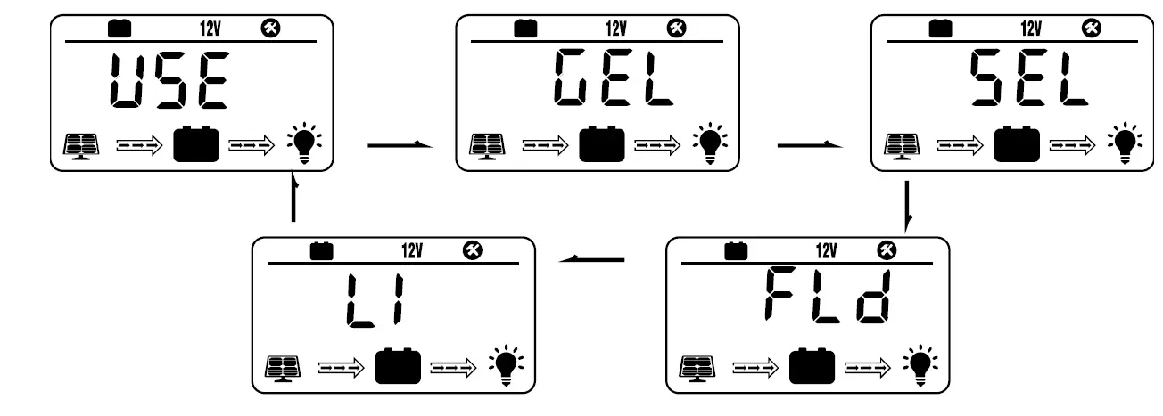
| Abbreviations | Battery Types | Description |
| FLD | flooded battery | auto-recognition with default parameters set for each type of batteries. |
| SEL | sealed/ AGM battery | |
| GEL | gel battery | |
| LI | lithium battery | some parameters can be customized |
| USE | advanced user mode | most parameters can be customized |
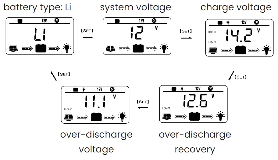
For Battery Type: Li
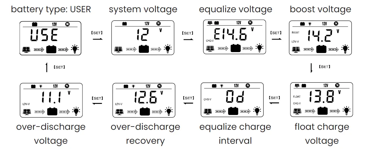
For Battery Type: USER
Load Mode Settings 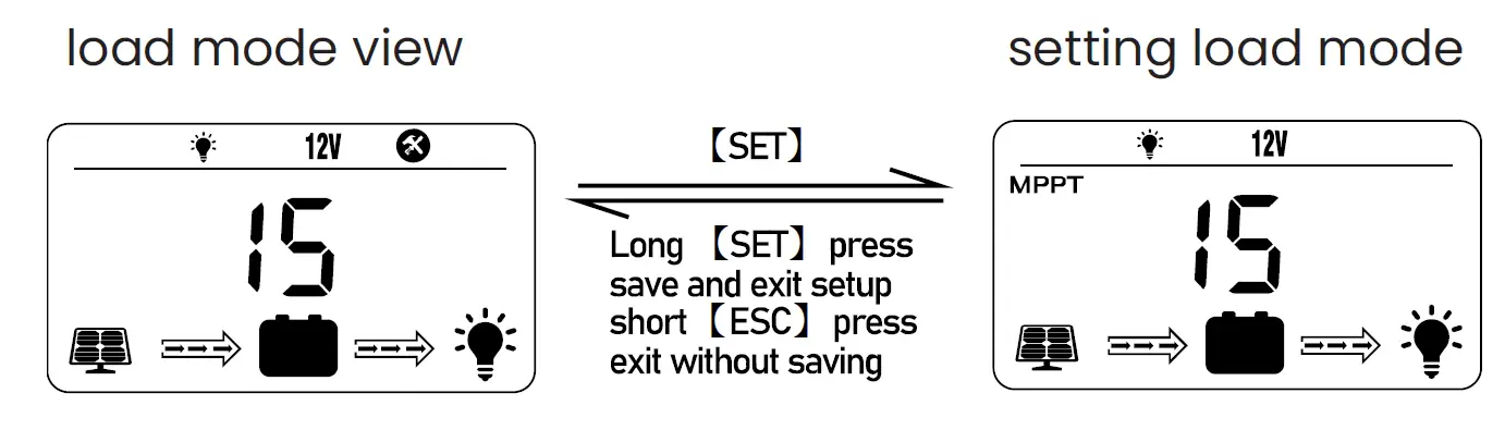
| Mode | Definition | Description |
| 0 | daylight auto-control | DC load turns on when no daylight is detected |
| 1-14 | daylight on/ timer off | DC load turns on when no daylight is detected DC load turns off according to timer |
| 15 | manual mode | DC load turns on/ off by pressing return key |
| 16 | testing mode | DC load turns on and off in quick succession |
| 17 | always on | DC load stays on |
Error Code Chart
| Code | Error | Description – Quick Troubleshoot |
| E00 | no error | no action needed |
| E01 | battery over- discharged | battery voltage is too low
|
| E02 | battery over-voltage | battery voltage has exceeded controller limit
|
| E04 | load short circuit | DC load short circuit |
| E05 | load overload | DC load power draw exceeds controller capability
|
| E06 | overheating | controller exceeds operating temperature limit
|
| E08 | solar over- amperage | solar array amperage exceeds controller rated input amperage
upgrade to a higher-rated controller |
| E10 | solar over-voltage | solar array voltage exceeds controller-rated input voltage
|
| E13 | solar reverse polarity | solar array input wires connected with reverse polarity
|
| E14 | battery reverse polarity | battery connection wires connected with reverse polarity
|
If additional techinical support is needed, please contact a professional.
Pont-to-Point Connections and Settings
DIP Device Configuration 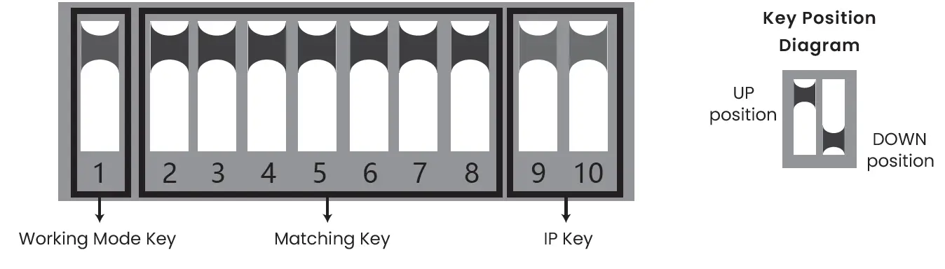
Key 1
Key 1 changes the working mode of the device. In the UP position, the device sets up an access point (AP) for use with a computer, recorder, etc. The DOWN position is for use with a camera.
Key 2 through Key 8
These keys are used for configuring AP devices together. They allow for 128 possible combinations.
Key 9 and Key 10
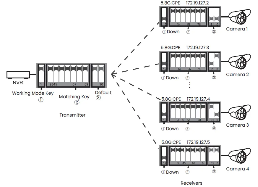
Keys 9 and 10 are for multi-point functionality and allows usage for up to 4 cameras. To use 4 cameras, configure the DIP switches as shown:
- On the recorder/ PC/ switch side have Keys 9 and 10 in the UP position.
- On the camera side select one of the following configurations for Keys 9 and 10.
- Camera 1: Key 9 (DOWN) | Key 10 (DOWN)
- Camera 2: Key 9 (DOWN) | Key 10 (UP)
- Camera 3: Key 9 (UP) | Key 10 (DOWN)
- Camera 4: Key 9 (UP) | Key 10 (UP)
- * Key configurations cannot be duplicated on Keys 9 and 10.
- * Turn off AP power before configuring.
- * IP address of camera must differ from AP address.
- * SSID of default AP group for DIP is not broadcast.
Camera Configuration Setup Figure
- NOTE:
Shown to the right are the possible key configurations that are available for the 4 cameras. Make sure the Working Mode Key and Matching Key are correctly set.
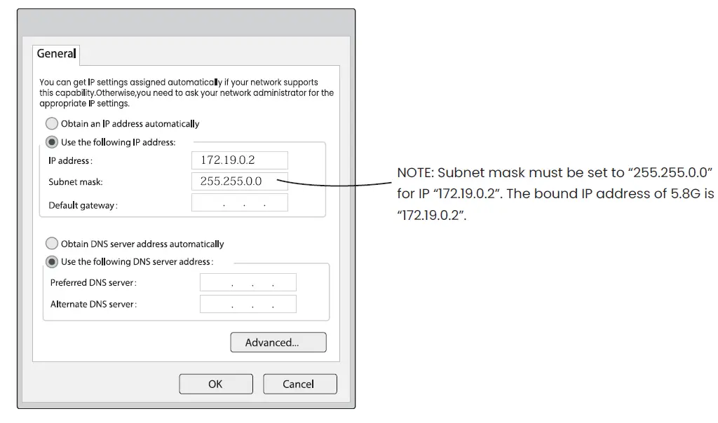
Signal Power Setting
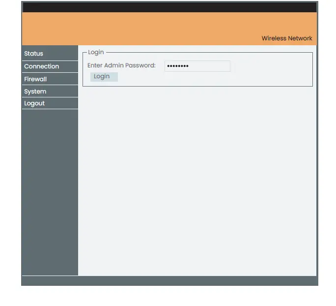
- Step 1
Configure the settings as shown to the left. The default password is: password.
- Step 2
Type the IP address of corresponding AP device in internet browser to get to the WEP page, using the default password (password) when prompted. Signal power can be set after logging in.
Transmit Power Configuration
Default is set to the maximum value. Adjust power level as needed.
Encryption Configuration
Customizable key that can be used for security. (The same key should be set in the transmitter and receiver.)
Distance Configuration
Default value is 2 kilometers (1.2 miles) but should be adjusted as needed.
(If the same distance value isn’t set in transmitter and receiver it will lead to a high latency and low bandwidth network connection.)
Country Code
In text mode, channels are determined by the dial-up button.
In all other modes, the channels are automatically selected .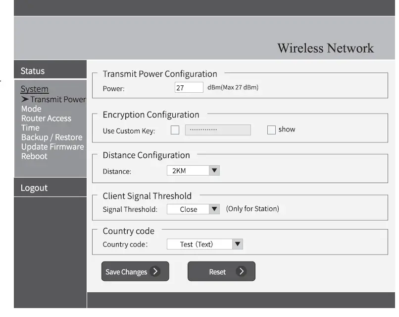
Troubleshooting an FAQ
- What should be noted when setting the AP key?
Make sure that the power is off. - How does the AP work without a power supply?
The AP gets power via its cable connection, called the PoE. Two cables are needed for this connection and for the AP to get power. A CAT5e cable is strongly recommended to be used. - How long can the PoE cable be?
The length depends on the power voltage and the quality of the cable. For 24V power, the cable should be no longer than 40 meters (131 feet). For 12V power, the cable should be no longer than 20 meters (65 feet). - Why does the signal light not work after switching it on?
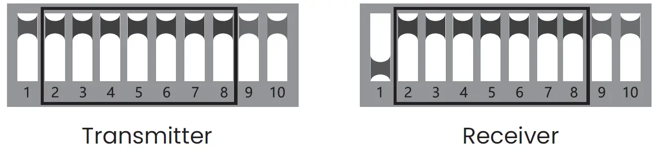
Please turn off AP power first. If the signal light is not working run the following troubleshooting test: Transmitter: Keep Keys 1 through 10 in UP position.
Receiver: Put Key 1 in the DOWN position and Keys 2 through 10 in the UP position.
After doing that, turn on the power and wait for three minutes.
NOTE: The distance between the transmitter and receiver should be more than 2 meters. See image below.  Why is the local network connection choppy after insalling the AP?
Troubleshoot a choppy network connection by utilizing one or both of the below methods.- Change the cable to see if that is the problem.
- Change the wireless channel to avoid signal interference.
- How do I log into the WEP page?
Follow steps 1 and 2 under the “Signal Power Setting” section and type in the IP address of the device in question on a network browser (for example, internet explorer).
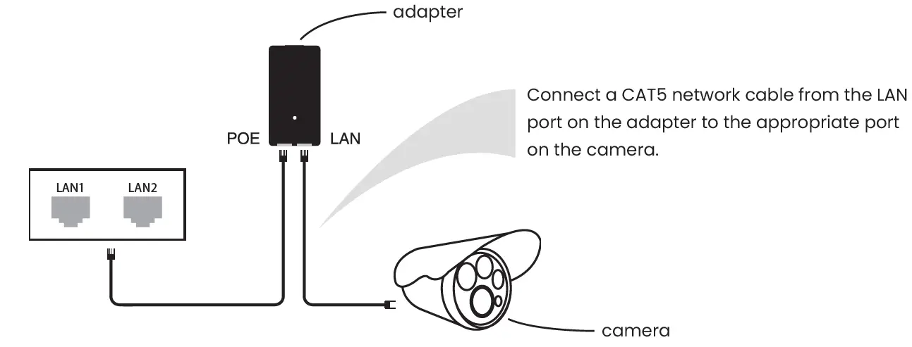
Why is there no video showing on the monitor despite having set up the AP and NVR?Connect the adapter that links the NVR to the yellow LAN port on the AP. - How do I reset the device?
Press and hold the RST button for 6 seconds while the unit is on. - What do the colors of the signal light mean?
 Why is the local network connection choppy after insalling the AP?
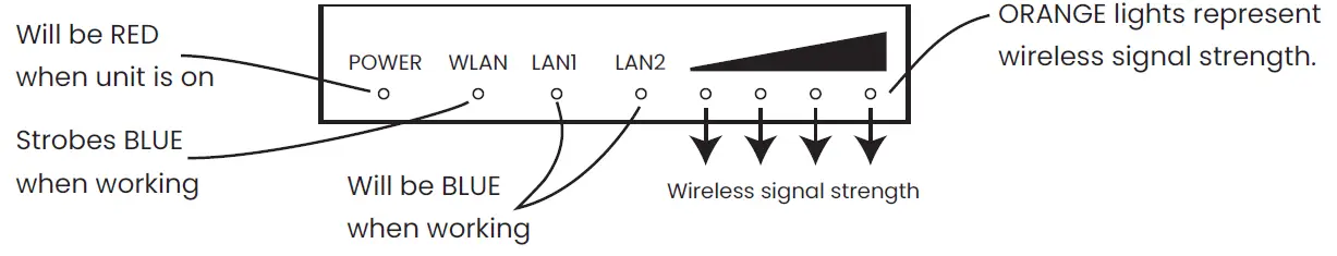
4G Router Setup Guide
- Step 1
Log into the computer network.
 How to obtain an IP address
To obtain an IP address, log into the computer network. An IP address will be automatically obtained. Default IP address: 192.168.110.251
Default login password: password
Step 2
Access overview by selecting the Status menu. 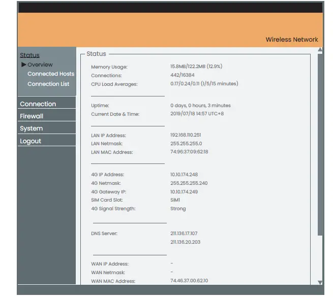
- Hardware status
Memory usage, number of connections, and CPU usage (timeline 1/5/15 minutes, respectively). - Time status
System run time and world time. - LAN port
LAN IP Address, LAN Netmask, LAN MAC Address. - G Network
4G IP Address, Netmask, Gateway IP, SIM Card Slot, Signal Strength.* - DNS Server
DNS Server
WAN Port
WAN IP Address, Netmask, MAC.
(WAN port needs to be connected to the external network)
*NOTE: 4G router reads SIM1 (lower card slot) by default. When the 4G router is started, the “Ping Watchdog” function detects network connectivity. If no response is received within the maximum time limit, 4G router will automatically restart and automatically switch to SIM2 (upper card slot) and continue to
detect after reboot until the network is back to normal. This process takes about 8–9 minutes.
Step 2
Accessing the Connected Hosts menu.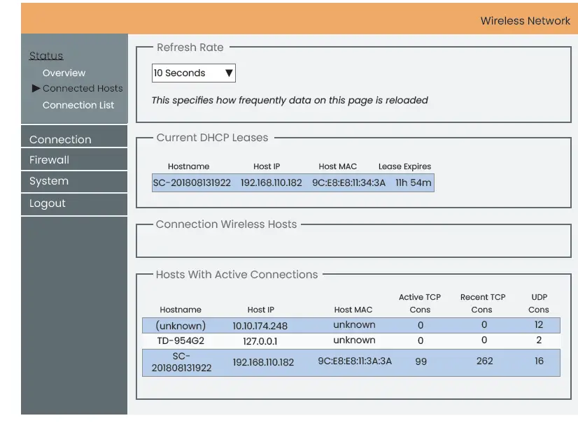
Further Information on the Connected Hosts
The page refresh time to display DHCP lease user information of active users can be set.
Step 3
Accessing the Connection List menu. 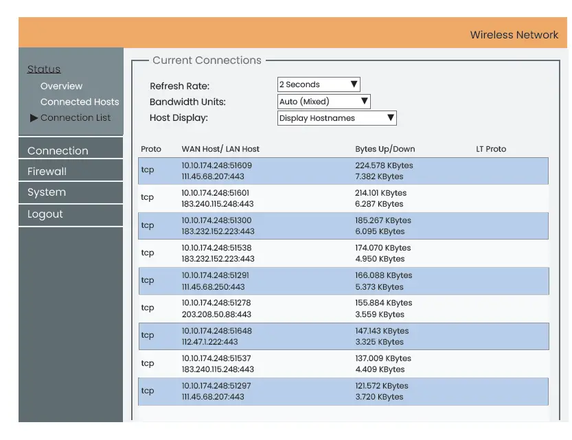
Further Information on the Connection Lists
You can set the page refresh time, display the host name/ IP address, and modify the traffic data unit.
How to Set Up Cameras for the Solar Surveillance System
- To record in cameras that support Micro SD
Insert the Micro SD card after opening the bottom cover of camera when the camera is unplugged from the solar surveillance device. Do not attempt to insert the Micro SD card after it is already connected to the solar surveillance device. Doing so might damage the camera or the SD card. For recommended SD card specifications, contact the manufacturer. - How to view the camera from a mobile phone
Access the app store from your phone and download and install EZView (for UNV) or Guard Viewer (for InVid). Once installed, add your camera by typing in the serial number in the app or by scanning the
QR code. For further information regarding accessing your camera from your mobile phone, refer to the manufacturer’s documention and guides. - How to use the NVR or VMS
To use EZStation (for UNV) or Guard Station (for InVid) follow the instructions provided by the manufacturer. If the camera and the NVR or VMS are on the same network then use the preferable IP connection. If they are not on the same network then use a cloud base connection (https://en.ezcloud.uniview.com for UNV) or (https://www.star4live.com for InVid).
Website: www.invidtech.com


