![]()
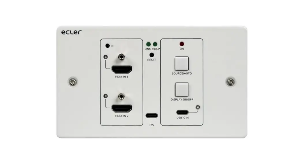
VEO-XWT44E
HDBASET EXTENDER
HDbaseT Wallplate Transmitter, EU format
USER MANUAL
v.20201217
IMPORTANT REMARK
![]() The lightning flash with the arrowhead symbol, within an equilateral triangle, is intended to alert the user to the presence of uninsulated “dangerous voltage” within the product’s enclosure that may be of sufficient magnitude to constitute a risk of electric shock to persons.
The lightning flash with the arrowhead symbol, within an equilateral triangle, is intended to alert the user to the presence of uninsulated “dangerous voltage” within the product’s enclosure that may be of sufficient magnitude to constitute a risk of electric shock to persons. The exclamation point within an equilateral triangle is intended to alert the user to the presence of important operating and maintenance (servicing) instructions in the literature accompanying the appliance.
WARNING (If applicable): The terminals marked with the symbol ” ” may be of sufficient magnitude to constitute a risk of electric shock. The external wiring connected to the terminals requires installation by an instructed person or the use of ready-made leads or cords.
WARNING: To prevent fire or shock hazards, do not expose this equipment to rain or moisture.
WARNING: An apparatus with Class I construction shall be connected to a mains socket-outlet with a protective earthing connection.
IMPORTANT SAFETY INSTRUCTIONS
- Read these instructions.
- Keep these instructions.
- Heed all warnings.
- Follow all instructions.
- Do not use this apparatus near water.
- Clean only with dry cloth.
- Do not block any ventilation openings. Install in accordance with the manufacturer’s instructions.
- Do not install near any heat sources such as radiators, heat registers, stoves, or other apparatus (including amplifiers) that produce heat.
- Do not defeat the safety purpose of the polarized or grounding-type plug. A polarized plug has two blades one wider than the other. A grounding-type plug has two blades and a third grounding prong. The wide blade or the third prong is provided for your safety. If the provided plug does not fit into your outlet, consult an electrician for the replacement of the obsolete outlet.
- Protect the power cord from being walked on or pinched particularly at the plugs, convenience receptacles, and at the point where they exit from the apparatus.
- Only use attachments/accessories specified by the manufacturer.
- Unplug the apparatus during lightning sorts or when unused for long periods of time.
- Refer all servicing to qualified personnel. Servicing is required when the apparatus has been damaged in any way, such as a power supply cord or plug is damaged, liquid has been spilled or objects have fallen into the apparatus, the apparatus has been exposed to rain or moisture, does not operate normally, or has been dropped.
- Disconnecting from mains: When switching off the POWER switch, all the functions and light indicators of the unit will be stopped, but fully disconnecting the device from the mains is done by unplugging the power cable from the mains input socket. For this reason, it always shall remain easily accessible.
- Equipment is connected to a socket-outlet with earthing connection by means of a power cord.
- The marking information is located at the bottom of the apparatus.
- The apparatus shall not be exposed to dripping or splashing and no objects filled with liquids, such as vases, shall be placed on the apparatus.
NOTE: This equipment has been tested and found to comply with the limits for a Class A digital device, pursuant to part 15 of the FCC Rules. These limits are designed to provide reasonable protection against harmful interference when the equipment is operated in a commercial environment. This equipment generates, uses, and can radiate radio frequency energy and, if not installed and used in accordance with the instruction manual, may cause harmful interference to radio communications. Operation of this equipment in a residential area is likely to cause harmful interference in which case the user will be required to correct the interference at his own expense.![]() WARNING: This product must not be discarded, under any circumstance, as unsorted urban waste. Take to the nearest electrical and electronic waste treatment center.
WARNING: This product must not be discarded, under any circumstance, as unsorted urban waste. Take to the nearest electrical and electronic waste treatment center.
NEEC AUDIO BARCELONA, S.L. accepts no liability for any damage that may be caused to people, animals, or objects due to failure to comply with the warnings above.
IMPORTANT NOTE
Thank you for choosing our Ecler VEO-XWT44E HDbaseT wallplate transmitter.
It is VERY IMPORTANT to carefully read this manual and to fully understand its contents before any connection in order to maximize your use and get the best performance from this equipment.
To ensure optimal operation of this device, we strongly recommend that its maintenance be carried out by our authorized Technical Services.
Ecler VEO-XWT44E comes with a 3-year warranty.
INTRODUCTION
Ecler VEO-XWT44 is an HDbaseT transmitter in a European 2-gang wallplate format. It allows extending one 4K video signal up to 40m over a single Cat 5e/6 cable or a FullHD signal up to 70m when connected to VEO-XRT44. It supports real 4K video signals at 60Hz with 4:4:4 YUV chroma subsampling and HDR 10 with a maximum bandwidth of 18Gbps. With the bidirectional PoC feature, the transmitter can be powered by the receiver and vice versa. VEO-XWT44 includes 2 HDMI 2.0 Inputs and one USB-C Input selectable via front panel button, automatic switching feature, or RS-232. It allows extending IR and a bidirectional RS-232 signal along with the video signal. A second front panel button can be used to switch ON/OFF a display via CEC or it can be alternatively programmed by IR learning or RS-232 to send two RS-232 commands, offering a simple and versatile control option.
Features:
- 4K HDMI wall-plate transmitter with 2 HDMI IN, and 1 USB-C IN
- Supports HDMI 2.0, 4Kx2K/60Hz/4:4:4 HDCP 2.2 compliant
- Video source auto-switching
- Video lossless compression for HDBaseT technology, transmission up to 40m@4K and 70m@1080p over CATx cable
- Displays can be turned ON/OFF via CEC & RS-232 commands by the `DISPLAY ON/OFF button
- RS-232 and IR pass-through.
- IR learning to control display on/off.
- EDID pass-through and smart managing
- Two-way PoC
- Supports CEC pass-through.
- Provides LEDs to indicate the current operating status.
- Firmware upgrade by Micro-USB port.
- ESD protection
PACKAGES CONTENT
1 x VEO-XWT44E Transmitter / Switcher
1 x Surface mount box EU
2 x Mounting screws
1 x 3-pin Euroblock
3 x 2-pin Euroblock
1 x Power Adapter (24V DC 1.25A) with international blades
1 x Quick guide and warranty
PANEL DESCRIPTIONS
6.1. Front Panel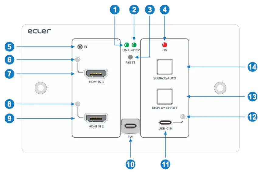
- LINK LED: The LED illuminates green when the transmitter is successfully connected to the receiver by a CATx cable.
- HDCP LED:
a. The LED illuminates green when the HDMI signal is transmitted with HDCP.
b. The LED blinks green when the HDMI signal is transmitted without HDCP.
c. The LED turns off when there is no HDMI signal input. - RESET: Press the recessed button to reboot this unit.
- POWER LED: The LED illuminates red when power is applied.
- IR: Built-in IR sensor for IR learning feature or IR pass-through control.
- HDMI IN 1 LED: The LED illuminates orange when the HDMI IN 1 port is connected to a source device, and it will turn green once the device is selected as the input source.
- HDMI IN 1: Type-A HDMI port to connect HDMI source.
- HDMI IN 2 LED: The LED illuminates orange when the HDMI IN 2 port is connected to a source device, and it will turn green once the device is selected as the input source.
- HDMI IN 2: Type-A HDMI port to connect HDMI source.
- FIRMWARE: USB-C port for firmware upgrade
- USB-C: Type-C USB to connect the Macbook or other device with USB-C output.
- USB-C LED: The LED illuminates orange when the USB-C port is connected to a source device, and it will turn green once the device is selected as the input source.
- DISPLAY ON/OFF: Press the blue-backlight button to turn on/off the display by automatically sending CEC and RS-232 commands (Programming required). For more details, please refer to 8.2 Display Control.
- SOURCE AUTO: o Press the blue-backlight button to select the next input source. o Press and hold the button at least 3 seconds to enable auto-switching mode. For more details, please refer to 8.1 Source Switching.
6.2. Rear Panel
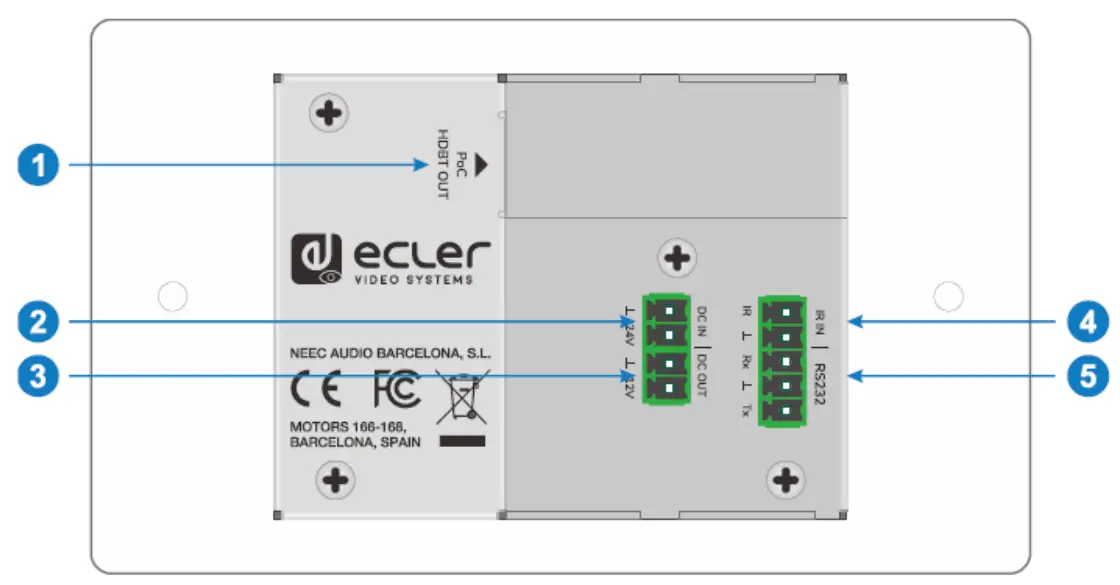
- DBT OUT (POC): RJ45 HDBaseT output port to connect to the HDBT IN port of the receiver by a CATx cable. It supports 12V-48V PoC to enable the switcher can be powered from a compatible receiver.
- DC IN: Power port to connect 24V DC power adapter.
- DC OUT: 2-pin terminal block to connect a compatible device which needs to be
powered. - IR IN: 2-pin terminal block to connect third-party control system.
- RS-232: 3-pin terminal block to connect a control device (e.g. PC) to send the RS-232 command to control this unit, or to control the far-end third party device. For more details, please refer to chapter RS-232 Control.
SYSTEM CONNECTION
The following diagram illustrates typical input and output connections that can be utilized with the switcher: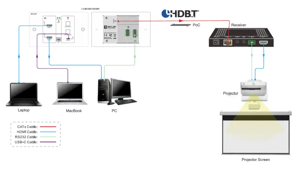 Note: We recommend the use of CATx shielded cables in order to guarantee the performances declared in the HDbaseT protocol specs.
8.1 Source Switching
- Press the SOURCE AUTO button to switch to next source device, and then the corresponding input LED will turn green.
- Press and hold the SOURCE AUTO button at least 3 seconds to enable auto-switching mode.
For auto-switching mode, remember the following rules:
- The switcher will switch to the first available active input starting at HDMI IN 1> HDMI IN 2 > USB-C.
- New input: Once a new input signal is detected, the switcher will automatically switch to this new signal.
- Source removed: When an active source is removed, the switcher will switch to the first available active input starting at HDMI IN 1.
- Reboot: The switcher can save the last configuration before losing power. If the last switching mode is auto-switching, the switcher will automatically enter auto-switching mode once rebooted, then detect all inputs and memorize their connection status for future rebooting use. If the last selected input source is still available, the switcher will switch to this input. Otherwise, it will switch to the first available active input source starting at HDMI IN 1.
- Exit auto-switching mode: Press and hold the SOURCE AUTO button for 3 seconds to exit the auto mode, and the input source will not be changed.
8.2 Display Control
- Press the blue-backlight DISPLAY ON/OFF button to turn on/off the display by automatically sending CEC and RS-232 commands (Programming required). When sending the ON command, the button will turn blue; when sending the OFF command and the button will be not illuminated.
- The DISPLAY ON/OFF button also can be programmed by IR learning feature or RS232 command. For more details, please refer to the User-Defined Button.
RS-232 Control
9.1. RS-232 Connection
According to the RS-232 control mode, there are three types of RS-232 connections for different applications.
- To control the switcher from local, please connect a control device (e.g. PC) to the RS-232 port of the switcher.
- To control the switcher from the remote, please connect a control device (e.g. PC) to the RS-232 port of the remote receiver.
- To control the far-end third-party device, please connect the control device (e.g. PC) to the RS-232 port of the switcher, and then please connect the third-party device (e.g. projector) to the RS-232 port of the remote receiver.
9.2. RS-232 Control
After devices are connected accordingly to the RS-232 connection diagram, VEOXWT44E can be controlled by a PC (using serial terminal software) or by a third-party control system.
Please set the correct COM number on your PC or control system and baud rate, data bit, stop bit, and parity bit as follows:
Baud rate: 9600.
Data bit: 8.
Stop bit: 1.
Parity bit: none.
With these parameters, it will be possible to communicate with the VEO device and send the commands listed in the next chapter.
RS-232 COMMANDS
The following table lists all the commands available for the VEO-XWT44E.
Note:
- Command ending: “<CR><LF>”.
- Feedback Error: “COMMAND ERROR” or “OUT OF RANGE”.
- In the table, “[“and “]” are symbols for easy reading and do not need to be typed in the command.
- Type the command carefully, it is case-sensitive.
10.1. Device Control
Command | Description | Feedback Example |
| #GET_FIRMWARE_VERSI ON | Get firmware version. | @V1.0.0 |
| #FACTORY_RESET | Restore factory default. | @FACTORY_RESET |
| #REBOOT | System reboot. | @REBOOT |
| #HELP | Get all command list. | |
| #SET_SIGNAL_DET TMDS | Set signal detecting mode to TMDS. Signal exist if detecting TMDS. | @SIGNAL_DET_MODE TMDS |
| #SET_SIGNAL_DET 5V | Set signal detecting mode to 5V. Signal exist if detecting 5V. | @SIGNAL_DET_MODE 5V |
| #GET_SIGNAL_DET | Get the signal detecting mode. | @SIGNAL_DET_MODE TMDS |
| @SIGNAL_DET_MODE 5V | ||
| #SET_KEYPAD_LOCK 0 | Unlock panel buttons. | @KEYPAD_LOCK 0 |
| #SET_KEYPAD_LOCK 1 | Lock panel buttons. | @KEYPAD_LOCK 1 |
| #GET_KKEYPAD_LOCK | Get panel buttons locking status. | @KEYPAD_LOCK 0 |
| @KEYPAD_LOCK 1 | ||
| #GET_STATUS | Get device status. |
10.2. Source Switching
Command | Description | Feedback Example |
| #SET_AV H1 | Switch to HDMI 1. | @AV H1 |
| #SET_AV H2 | Switch to HDMI 2. | @AV H2 |
| #SET_AV C | Switch to USB-C. | @AV C |
| #GET_AV | Get the current input source. | @AV H1 |
| @AV H2 | ||
| @AV C | ||
| #SET_AUTO_SWITCH 1 | Enable auto-switching mode. | @AUTO_SWITCH 1 |
| #SET_AUTO_SWITCH 0 | Enable manual switching mode. | @AUTO_SWITCH 0 |
| #GET_AUTO_SWITCH | Get the source switching mode. | @AUTO_SWITCH 1 |
| @AUTO_SWITCH 0 |
10.3. HDCP Mode
Command | Description | Feedback Example |
| #SET_OUTPUT_HDCP ACTIVE | Set the HDCP mode to ACTIVE for the output port. | @OUTPUT_HDCP ACTIVE |
| #SET_OUTPUT_HDCP ON | Set the HDCP mode to ON for the output port. | @OUTPUT_HDCP ON |
| #SET_OUTPUT_HDCP OFF | Set the HDCP mode to OFF for the output port. | @OUTPUT_HDCP OFF |
| #GET_OUTPUT_HDCP | Get the HDCP mode of the output port. | @OUTPUT_HDCP ACTIVE |
| @OUTPUT_HDCP ON | ||
| @OUTPUT_HDCP OFF |
10.4. EDID Management
The Extended Display Identification Data (EDID) is used by the source device to match its video resolution with the connected display. By default, the source device obtains its EDID from the connected display, but when the video resolution of the display is higher than 4K@30Hz, the video resolution of the source device will be 4K@30Hz. Meanwhile, since the display with different capabilities is connected to the switcher, the below RS-232 commands can be used to set the EDID to a fixed value to ensure compatibility in video resolution.
| Command | Description | Feedback Example |
| #SET_EDID_MODE 0 | EDID bypass. | @EDID_MODE 0 |
| #SET_EDID_MODE 1 | 1920×1080@60Hz Stereo | @EDID_MODE 1 |
| #SET_EDID_MODE 2 | 1920×1080@60Hz Lossless | @EDID_MODE 2 |
| #SET_EDID_MODE 3 | 3840×2160@30Hz Stereo (Default) | @EDID_MODE 3 |
| #SET_EDID_MODE 4 | 3840×2160@30Hz Lossless | @EDID_MODE 4 |
| #SET_EDID_MODE 5 | 3840×2160@60Hz Stereo | @EDID_MODE 5 |
| #SET_EDID_MODE 6 | 3840×2160@60Hz Lossless | @EDID_MODE 6 |
| #SET_EDID_MODE 7 | 3840×2160@60Hz HDR Stereo | @EDID_MODE 7 |
| #SET_EDID_MODE 8 | 3840×2160@60Hz HDR Lossless | @EDID_MODE 8 |
| #SET_EDID_MODE 9 | Select the user-defined EDID. If the user-defined EDID has not been uploaded, sending this command will set EDID to “3840×2160@30 Stereo”. | @EDID_MODE 9 |
| #UPLOAD_USER_EDID | Upload the user-defined EDID. | @USER_EDID READY PLEASE SEND EDID DATA IN 10S OK/ERROR |
| #GET_EDID_MODE | Get the current EDID. | @EDID_MODE 0 |
| @EDID_MODE 1 | ||
| @EDID_MODE 2 | ||
| @EDID_MODE 3 | ||
| @EDID_MODE 4 | ||
| @EDID_MODE 5 | ||
| @EDID_MODE 6 |
| Command | Description | Feedback Example |
| @EDID_MODE 7 | ||
| @EDID_MODE 8 | ||
| @EDID_MODE 9 |
10.5. Display Control
| Command | Description | Feedback Example |
| #SET_DISPLAY ON | Power on the display device (CEC/RS232/IR). | @SET_DISPLAY ON |
| #SET_DISPLAY OFF | Power off the display device (CEC/RS232/IR). | @SET_DISPLAY OFF |
| #SET_VOL + | Volume up the display device. | @VOL + |
| #SET_VOL – | Volume down the display device. | @VOL – |
| #SET_VOL MUTE | Mute the display device. | @VOL MUTE |
| #AUTO_CEC_SET_PANEL_ OPEN | Enable the function to automatically turn on/off the display device. The display device will automatically turn on when detecting a signal input, or it will automatically turn off when removing the last input. | @OPEN CEC DISPLAY ON/OFF WHEN SIGNAL/NOSIGNAL |
| #AUTO_CEC_SET_PANEL_ CLOSE | Disable the function to automatically turn on/off the display device. | @CLOSE CEC DISPLAY ON/OFF WHEN SIGNAL/NO SIGNAL |
| #GET_AUTO_CEC_SET_PA NEL | Get the function status of automatically turning on/off the display device. | @OPEN CEC DISPLAY ON/OFF WHEN SIGNAL/NO SIGNAL |
| #AUTO_CEC_PANEL_TIME [PARAM]: | Set the delay time of sending a command to [PARAM]. After removing the last input, the display device will be automatically turned off when the delay time is up.[PARAM] = 0 ~ 10000. | @DELAY TIME TO %d MINUTES, TO TURN OFF THE DISPLAY IF NO SOURCE DETECTED |
| #GET_AUTO_CEC_PANEL _TIME | Get the delay time of sending command of turning off display device. | @DELAY TIME TO %d MINUTES, TO TURN OFF THE DISPLAY IF NO SOURCE DETECTED |
10.6. Third-party Device Control
| Command | Description | Feedback Example | ||||||||||||||||
| #SEND_A_[PARAM]: xxxx | Send the ASCII command “XXXX” to the third-party device which is connected to the HDBaseT receiver. The baud rate of the third-party device is [PARAM]. [PARAM] = “01~07”. Represents the baud rate of the third-party device.
| #SEND_A_01:ABCD123 | ||||||||||||||||
| @SEND_ASCII_STRING ABCD123 | ||||||||||||||||||
| #SEND_H_[PARAM]: xxxx | Send the HEX command “XXXX” to the third-party device which is connected to the HDBaseT receiver. The baud rate of the third-party device is [PARAM]. [PARAM] = “01~07”. represents the baud rate of the third-party device.
| #SEND_H_01:11 22 33 | ||||||||||||||||
| @SEND_HEX_STRING 11 22 33 |
Pressing the DISPLAY ON/OFF button allows turning the display on and off via CEC commands. If the display doesn’t support CEC, the DISPLAY ON/OFF button can be programmed by IR learning feature or RS-232 command.
11.1. IR learning programming
Please follow the IR learning steps below in order to define the DISPLAY ON/OFF button functions:
- Press and hold the DISPLAY ON/OFF button at least five seconds until the SOURCE AUTO button starts to flash in order to enable the IR learning mode.
- Press the DISPLAY ON/OFF button to choose the ON or OFF IR command to be set:
Button LED lighting indicates that DISPLAY ON mode is selected.
Button LED flashing indicates that DISPLAY OFF mode is selected. - Point the IR remote at the IR sensor and press the respective button on the IR remote.
- The SOURCE AUTO and DISPLAY ON/OFF buttons will keep lit for 3 seconds to indicate that IR command has been learned: the SOURCE AUTO button will keep flashing and the DISPLAY ON/OFF button will be off.
- Press and hold the DISPLAY ON/OFF button for five seconds again to exit IR learning mode. Please note that The IR learning function will self-terminate after 30 seconds of inactivity.
11.2 RS-232 programming
| Command | Description | Feedback Example | ||||||||||||||||||||||
| #SET_KEY_RS232 ON | Enable sending RS232 command when the DISPLAY ON/OFF button has been pressed. | @KEY_RS232_SENDING ON | ||||||||||||||||||||||
| #SET_KEY_RS232 OFF | Disable sending RS232 command when the DISPLAY ON/OFF button has been pressed. | @KEY_RS232_SENDING OFF | ||||||||||||||||||||||
| #GET_KEY_RS232 | Get the Enabled/Disabled status of sending the RS232 command when the DISPLAY ON/OFF button has been pressed. | @KEY_RS232_SENDING ON | ||||||||||||||||||||||
| @KEY_RS232_SENDING OFF | ||||||||||||||||||||||||
| #SET_ON_[PARAM1]_[P ARAM2]: xxxx | Set the RS232 command “XXXX” to be sent to the third-party device when the DISPLAY ON button has been pressed. ⚫ [PARAM1] = A/H:
⚫ [PARAM2] = “01~07”: Represents the baud rate of the third-party device.
| #SET_ON_A_01:ABCDEFG @SET_ON_A_01:ABCDEFG |
| #SET_OF_[PARAM1]_[PA RAM2]_ [PARAM3]: xxxx | Set the RS232 command “xxxx” to be sent to the third- party device when the DISPLAY OFF button has been pressed. [PARAM1] = A/H:
[PARAM2] = “01~07”: Represents the baud rate of the third-party device
[PARAM3] = “01~100”: Represents the delay time of command sending | #SET_OF_A_01_01:ABCDEF G |
| #SET_KEY_CEC ON | Enable sending CEC command when the DISPLAY ON/OFF button has been pressed. | @KEY_CEC_SENDING ON |
| #SET_KEY_CEC OFF | Disable sending CEC command when the DISPLAY ON/OFF button has been pressed. | @KEY_CEC_SENDING OFF |
| #GET_KEY_CEC | Get the Enabled/Disabled status of sending the CEC command when the DISPLAY ON/OFF button has been pressed. | @KEY_CEC_SENDING ON |
| @KEY_CEC_SENDING OFF | ||
| #SET_KEY_IR ON | Enable sending IR data when the DISPLAY ON/OFF button has been pressed. | @KEY_IR_SENDING ON |
| #SET_KEY_IR OFF | Disable sending IR data when the DISPLAY ON/OFF button has been pressed. | @KEY_IR_SENDING OFF |
| #GET_KEY_IR | Get the Enabled/Disabled status of sending IR data when the DISPLAY ON/OFF button has been pressed. | @KEY_IR_SENDING ON |
| @KEY_IR_SENDING OFF |
TECHNICAL SPECIFICATIONS
| Supported Resolutions | Up to 4Kx2K@60Hz 4:4:4 8bit HDR10 | |
| Colorspace | RGB, YCbCr | |
| Chroma Subsampling | 4:4:4, 4:2:0 | |
| Color depth | 8-bit, 10-bit, 12-bit, 16-bit only @4K30 | |
| Signal Bandwidth | 18 Gbps | |
| HDCP | 2.2/1.4 Compliant | |
| Video Connectors | 2xType-A Female HDMI, Type-C Female USB | |
| Audio performances | Digital, DTS, Dolby TrueHD, DTS-HD Master Audio | |
| Audio performances | ||
| Audio Formats | PCM 2Ch, PCM 5.1, PCM 7.1, Dolby Digital, DTS, Dolby TrueHD, DTS-HD Master Audio | |
| Sample Rate | 32kHz, 44.1kHz, 48kHz, 88.2kHz, 96kHz, 176.4kHz, 192kHz | |
| Bit rate | up to 24-bit | |
| Frequency Response | 20Hz – 20KHz, | ±3dB |
| Max Output Level | 2.0Vrms | ± 0.5dB |
| SNR | > 85dB | 20Hz-20 kHz bandwidth |
| Control performances | ||
| TX Control ports | IR Receiver, | IR Sensor Embedded |
| RESET SOURCE/AUTO IR Control RS-232 FW | Button Back-lit button 2-pin Euroblock 3-pin Euroblock Type-C USB Female | |
| CEC | |||
| ON/OFF commands Back-lit button or RS-232 | |||
| VOL+, VOL- | RS-232 | ||
| MUTE | RS-232 | ||
| General | |||
| HDMI Distance | up to 10 meters / 33 ft with Ecler VEO cables | ||
| Transmission Standard | HDbaseT | ||
| Cat.5e/6 Distance | CAT5e/6 @ 4K up to 35 m / up to 115 feet CAT6a/7 @ 4K up to 40 m/ up to 130 feet CAT5e/6 @ 1080p up to 60 m / up to 197 feet CAT6a/7 @ 1080p up to 70 m / up to 230 feet | ||
| Operating Temperature | -10 to +55°C (14 to +131 °F) | ||
| Humidity | 10 to 90 % RH (no condensation) | ||
| Power Consumption | 22W (Max) | ||
| Power Supply | Input: | AC 100V – 240V 50/60Hz | |
| Output | DC 24V—1.25A | ||
| Dimensions | 146mm x 86mm x 42mm (5.75″ x 3.39″ x 1.65″) | ||
| Weight | 294g (0.648 Ibs) | ||
MECHANICAL DIAGRAM

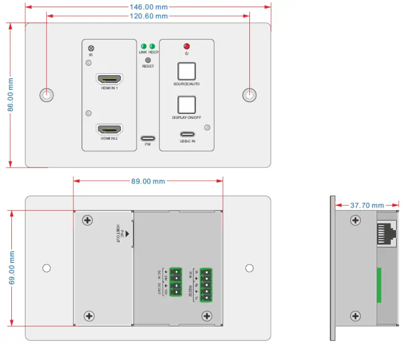
All product characteristics are subject to variation due to production tolerances. NEEC AUDIO BARCELONA S.L. reserves the right to make changes or improvements in the design or manufacturing that may affect these product specifications.
For technical queries contact your supplier, or distributor or complete the contact form on our website, in Support / Technical requests.
Motors, 166-168 08038
Barcelona – Spain – (+34) 932238403
[email protected]
www.ecler.com ![]()


