ABB Change-over switches Installation Guide
Installation Instruction, OTM_F_C_
OTM30-125-C_
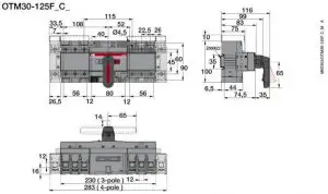
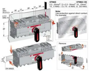
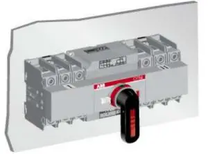
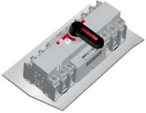
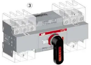
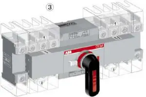
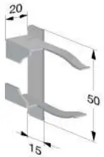
Mounting Positions
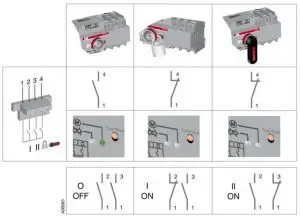
Control Circuit
![]() Only an authorised electrician may perform the electrical installation and maintenance of motorized switch. Do not attempt any installation or maintenance actions when a motorized switch is connected to the electrical mains. Before starting work, make sure that the switch is de-energised.
Only an authorised electrician may perform the electrical installation and maintenance of motorized switch. Do not attempt any installation or maintenance actions when a motorized switch is connected to the electrical mains. Before starting work, make sure that the switch is de-energised.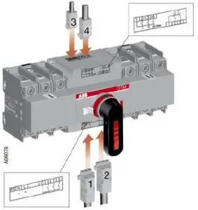
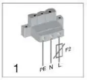
- Terminal for motor operator voltage supply

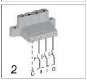
- Control terminal for push buttons
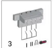
- Terminal for state information (also used with the automatic control unit)
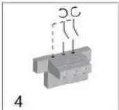
- Control terminal for automatic control unit (If used OMD controller)
![]() Do not couple power for the control terminal. See the correct terminal for the power supply.
Do not couple power for the control terminal. See the correct terminal for the power supply.
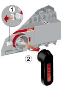
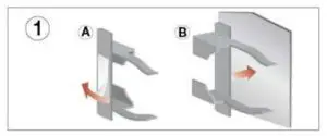
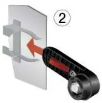
Manual operation: Local
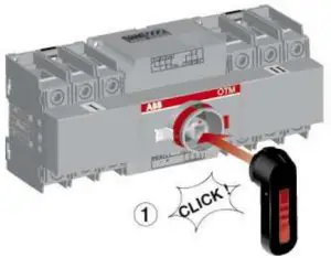
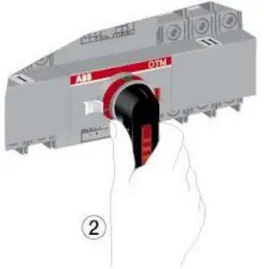
![]() Electrical operation is prevented when the handle is attached to the switch panel.
Electrical operation is prevented when the handle is attached to the switch panel.
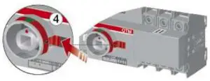
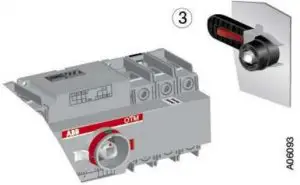
Electrical operation: Remote
![]() Never open any covers on the product. There may be dangerous external control voltages inside the motorized switch even if the voltage is turned off.
Never open any covers on the product. There may be dangerous external control voltages inside the motorized switch even if the voltage is turned off.
![]() Never handle control cables when the voltage of the motorized switch or external control circuits are connected.
Never handle control cables when the voltage of the motorized switch or external control circuits are connected.
![]() Exercise sufficient caution when handling the unit.
Exercise sufficient caution when handling the unit.


Automatic Operation
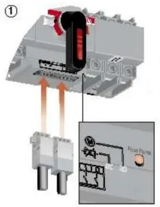
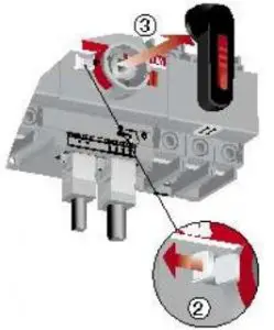
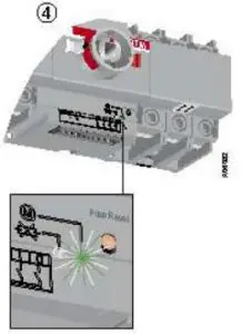
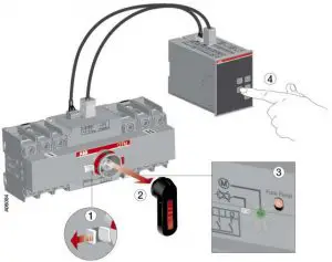
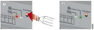
Resetting Fuse

Impulse Control
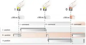
Continuous Control
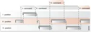
![]() If a new command is given before the switch has reached the position of the previous command, the internal protection may operate.
If a new command is given before the switch has reached the position of the previous command, the internal protection may operate.
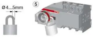
Locking
Prevent Manual and Electrical Operation
![]() Locking Possible at any position. Check position before locking.
Locking Possible at any position. Check position before locking.
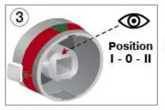
State Information
Technical Data
Motor operator, control circuit | Value | Cabling/Rating |
| Rated operational voltage U [V] | 110-240 Vac/dc 50-60Hz | |
| 24 Vdc | ||
| Operating voltage range | 0.85.. 1.1 x U | |
| Operating angle | 90° 0-I, I-0, 0-II, II-0; 180° I-0-II | |
| Operating time | See Table 2 | |
| Protection degree | IP 20, front panel | |
| Rated impulse withstand voltage Uimp | 4 kV | |
| Voltage supply | PE N L | 1,5 -2,5mm2 |
| F2 | Max. MCB 16A | |
| Control terminal for the push-buttons | C II I 0 | 1,5 -2,5mm2 |
| Maximum cable length | 100 m | |
| Terminal for state information Also used with the automatic control unit | 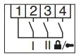 | 1,5mm2
3A AC-1/250V |
| Common, voltage supply | 1 | |
| Position of change-over switch I | 2 | |
| Position of change-over switch II | 3 | |
| Handle attached or motor operator locked | 4 | |
| SCPD | Max. MCB C2A | |
| Control terminal for automatic control unit If used OMD_ controller | 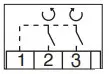 | 1,5-2,5mm2 |
| Common, voltage supply from motor operator | 1 | 24VDC |
| Close switch I or open switch II | 2 | 24VDC 500mW |
| Close switch II or open switch I | 3 | 24VDC 500mW |
| Operating temperature | -25… +55 °C | |
| Transportation and storage temperature | -40… +70 °C | |
| Altitude | Max. 2000m |
Table 1 : General technical data of motor operators.
| Type | Voltage Ue [V] | Nominal current a) In [A] | Current Inrush a) A] | Operating time a) I-0, 0-I, 0-II, II-0 [s] | Operating transfer time a) I-II or II-I [s] | OFF-time when operating a) I-II or II-I [s] |
| OTM40…125_C | 110-240 Vac/dc | 0,2 – 0,5 | 1,5 – 3,0 | 0,5 – 1,0 | 1,2 – 1,5 | 0,4 – 0,8 |
| 24 Vdc | 0,6 | 3,6 | 0,6 – 1,3 | 1,4 – 2,1 | 0,6 – 1,0 |
Table 2: Specified technical data of motor operators.
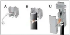
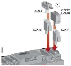
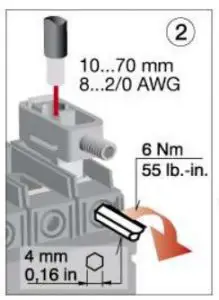
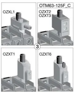
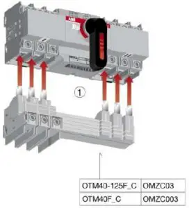
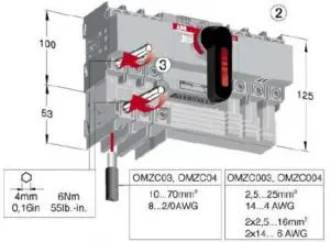
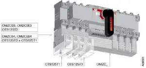
Terminal clamp sets OZX_, Bridging bars OMZC_
OZX_
OMZC_
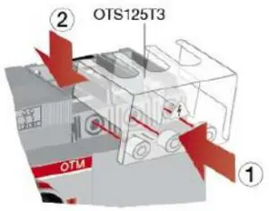
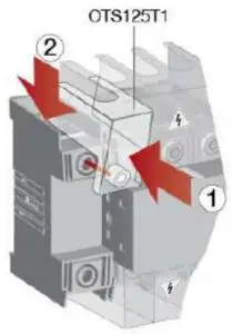
OTS_
OA_
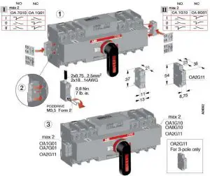
OTVS0
OTP_
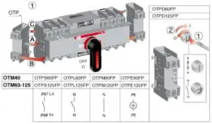
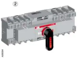
ABB Oy
Low Voltage Switches
P.O Box 622
FI-65101 VAASA, Finland
Telephone +358 10 22 11
Telefax +358 10 22 45708
www.abb.com


