M-gears MK104 BLE Keyless System Control Box User Manual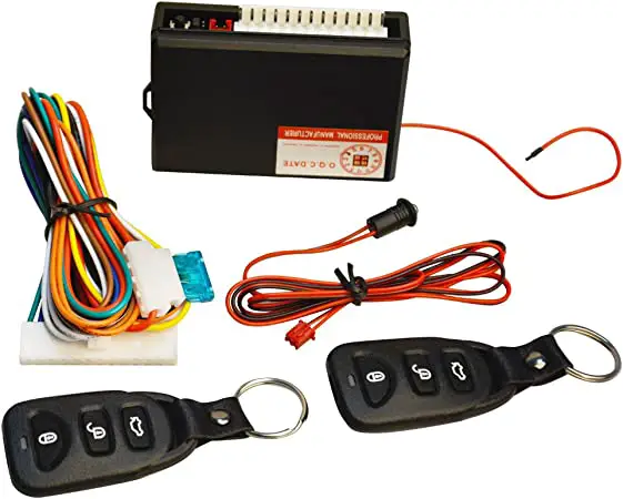
Revision History
| Date | Release | Author | Description |
| 2022/7/1 | R01 | Lance/Justin | R01 |
| 2022/7/7 | R02 | Lance/Justin | Add PCBA Dimension |
| 2022/9/19 | R03 | Lance/Justin | Add NCC Notice Information |
| 2022/9/22 | R04 | Lance/Justin | Correct Antenna model name |
| 2022/10/7 | R05 | Lance/Justin | Add device use instructions |
| 2022/10/7 | R06 | Lance/Justin | Remove BD |
| Date | Author | Document(s) |
Electrical Characteristics
| Item | Spec |
| Rated Voltage | DC 12V |
| Operation Voltage Range | DC 8~16V |
| Operation Temperature | -20℃ ~ +80℃ |
| Storage Temperature | -40℃ ~ +85℃ |
| Standby Current | <2mA |
| Maximum Bonding Devices (Keyfobs) | 4 |
| BLE transmit power | 6 dBm (typ.) |
| BLE receive sensitivty level | -90dBm (LE_1M_RX) |
| LF frequency | 125K Hz |
| LF modulation scheme | OOK |
| Solenoid Drive Signal | PWM 12V,Duty Cycle 50%, 20KHz |
| Buzzer Drive Signal | DC 12V, 100mA |
| LED Drive Signal | DC 12V, 50mA |
| Turn Light Drive Signal | DC 12V,1A |
Pin Definition
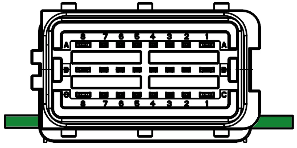
| PIN NO. | Pin Name | Pin Type | Note |
| A1 | Turn Signal 1 | OUT | (Reserved) |
| A2 | Micro Switch Sensor | IN | |
| A3 | Micro Switch Signal | OUT | |
| A4 | LED_GND | GND | |
| A5 | RED_LED | OUT | DC 12V |
| A6 | BLUE_LED | OUT | DC 12V |
| A7 | ON_Sensor | IN | |
| A8 | VDD | POWER | Power Supply 12V |
| B1 | Turn Signal 2 | OUT | (Reserved) |
| B2 | Buzzer – negative | GND | |
| B3 | Buzzer – positive | OUT | DC 12V |
| B4 | 125 KHz Antenna Data2 | OUT | |
| B5 | 125 KHz Antenna Data1 | OUT | |
| B6 | Solenoid – negative | GND | |
| B7 | Solenoid – positive | OUT | 12V, Duty Cycle 50%,20KHz |
| B8 | GND | GND | GROUND |
| C1 | NC | ||
| C2 | NC | ||
| C3 | NC | ||
| C4 | NC | ||
| C5 | Output signal 2(P) | OUT | (Reserved) |
| C6 | Output signal 1(O) | OUT | (Reserved) |
| C7 | NC | ||
| C8 | NC |
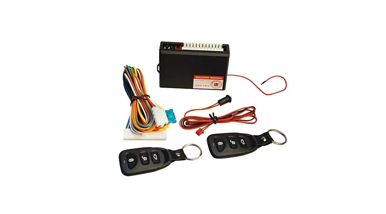
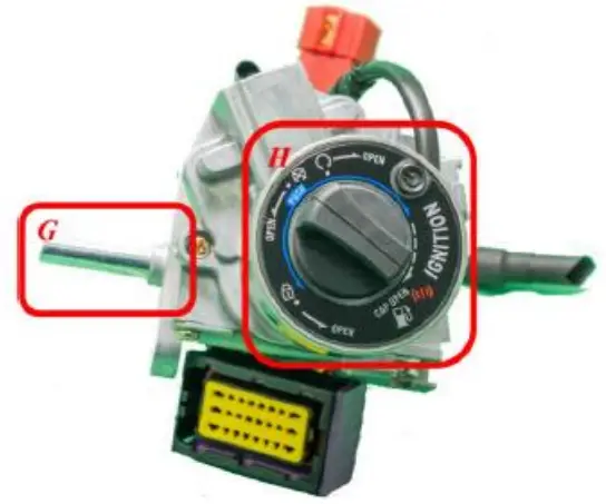
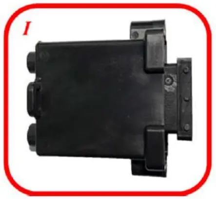
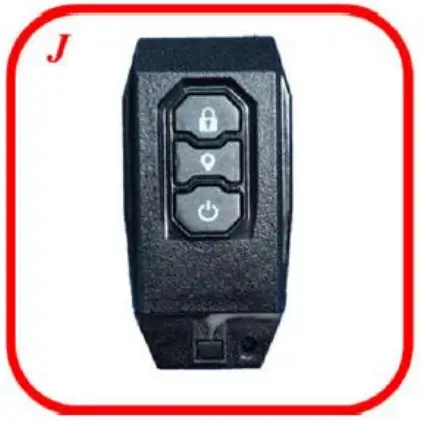
Product Parts Description
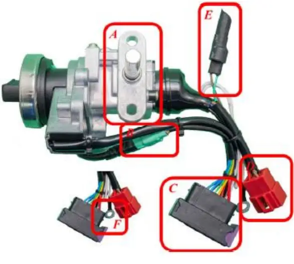
- A. Attachment Point: Locking point to fix the product to the body of the vehicle.
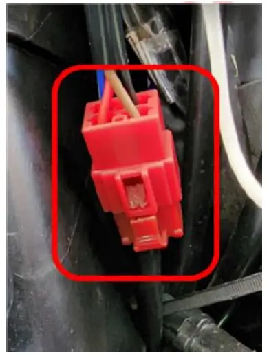
- B. Control Panel Connector: Connector to connect the control panel and control box
- C. Control Box Connector: Connector to connect control box
- D. Vehicle Connector: Connector to connect the product to the vehicle body
- E. Buzzer: Components that produce a corresponding beep sound when the product is in motion
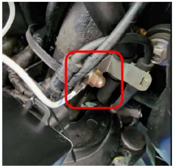
- F. Control Box Ground Pin: Ground wire of controller
- G. Steering Lock Bar: bar for locking vehicle steering handle
- H. Control Panel: Control Panel for user-operated
- I. Control Box: BLE Keyless system control box assembly.
- J. Smart Keyfob: Smart keyfob for keyless operation.
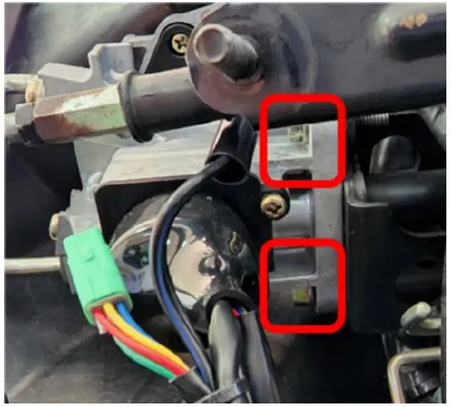
Product Installation
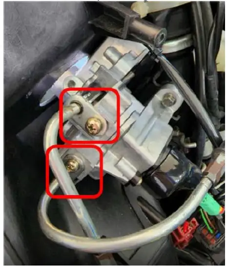
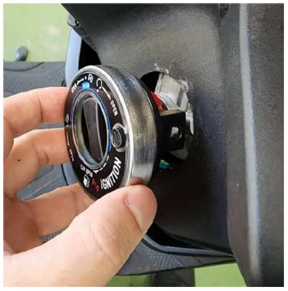
- Remove the original main switch.
- Fix Keyless main switch: Fix the keyless main switch to the frame.

- Install the cables for the fuel tank cover and seat cushion lock: Install the cables for the fuel tank cover and seat cushion lock in the same way as the original installation.

- Install the control panel: Install the control panel from the other side and lock it to the Keyless main switch.

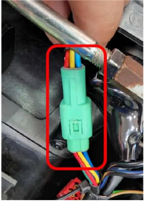
- Connect the control panel connector: After fixing the control panel, connect the control panel connector to the mating connector.

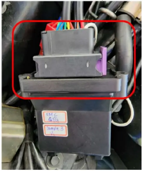
- Connect the control box: Connect the control box to the Keyless main switch.

- Connect the Keyless main switch to the vehicle: Connect the Keyless main switch to the vehicle body connector.

- Connect the Keyless main switch ground wire to the vehicle: Attach the ground wire to the frame metal.

Product Instructions
Smart Key (Smart keyfob button description)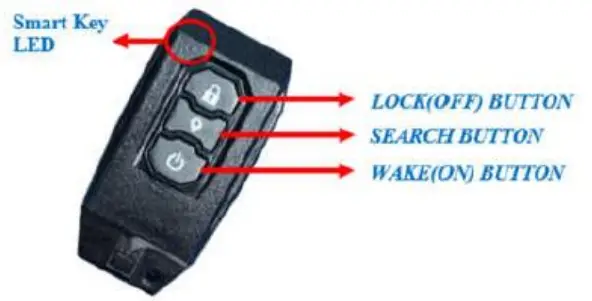
(Control Panel function description)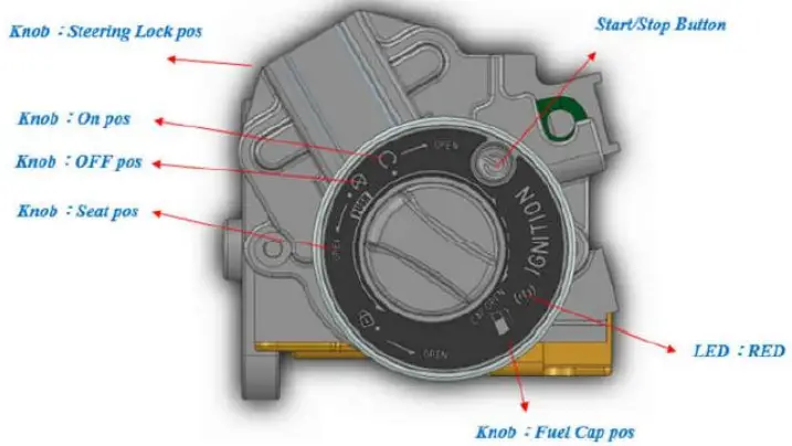
Keyless System Unlock
Press the Wake (ON) Button of the smart keyfob to remotely unlock and wake up the Keyless System.
Keyless System Lock
When press the Lock (OFF) Button of the smart keyfob , the Buzzer will beep once and the Keyless System will be locked, so even if the Smart Keyfob is within the sensor range, the Start/Stop Button on the control panel cannot be used to wake it up.
Keyless System Wake up
After successful authentication, wake up the Keyless System, and then you can operate the Knob on the control panel.
Keyless System Unlock
- Press the Wake (ON) Button on the Smart Keyfob to wake up the Keyless System.
- Press the Start/Stop Button on the control panel to wake up the Keyless System.
Keyless System Lock
Press the Wake (on) Button on the Smart Keyfob to wake up the Keyless System and set the system to “Unlock” state.
Keyless System Standby
- Press the Lock (OFF) Button on the Smart Key to put the Keyless System into standby and set the system to “Lock” state.
- Press the Start/Stop Button on the control panel to put the Keyless System into standby mode.
- After 10 seconds of inactivity, the Keyless System automatically enters standby mode.
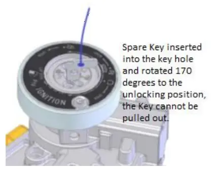
Keyless System Backup Method
When the vehicle battery is damaged and the Keyless System does not work properly or the Smart Keyfob battery is dead, you can use the Keyless System Backup mechanism to unlock the vehicle and operate the vehicle.
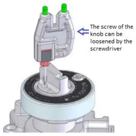
- Using the spare tool, remove the screwdriver and fix it.

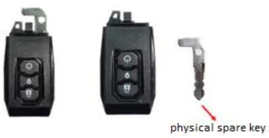
- Remove the physical spare key from the Smart Keyfob

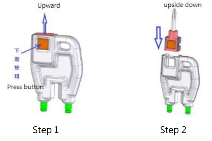
- Remove the Knob Cap from the Keyless Main Switch.

- Use the spare tool to remove the screw to reveal the spare key hole.

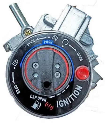
- Insert the spare key and turn the red dot to align with Unlock point.

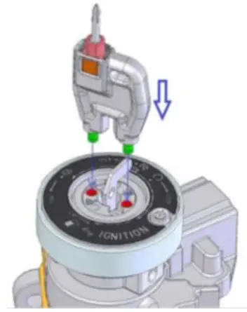
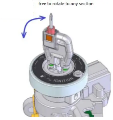
- Use the two levers of the spare gadget and insert them into the two holes.

- All functions can be operated immediately.

Other product function
Warning of authentication failure
When the legal Smart Keyfob is not in the sensing range, pressing the Start/Stop Button of the control panel will not wake up and there will be a flashing red light warning.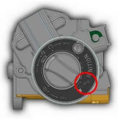
- Keyless system protection mechanism
When 6 consecutive attempts are made to wake up the Keyless System, the Keyless System lock warning appears and the Keyless System is then set to “Lock” status, requiring a Smart Key to unlock it. - Backup Mechanism Alert
When using the backup mechanism to force the Knob to the “On” position, the red light continues to blink after the LED Blue/Buzzer warning, and when turned back to OFF, the LED Blue/Buzzer warning again. - Smart Keyfob power saving mode.
When the Smart Key or Keyless System is not operated for three days, the Smart Key enters power saving mode and needs to be released by pressing the any key on the Smart Key. - Smart Keyfob Low Battery Alert
When the battery in the Smart Keyfob is too low (2.7V), the RED LED of the control panel will remain on when the Keyless wakes up successfully until the Keyless System enters standby mode.
NCC Interference Statement
Without permission granted by the NCC, any company, enterprise, or user is not allowed to change frequency, enhance transmitting power or alter original characteristic as well as performance to an approved low power radio-frequency devices. The low power radio-frequency devices shall not influence aircraft security and interfere legal communications; If found, the user shall cease operating immediately until no interference is achieved. The said legal communications means radio communications is operated in compliance with the Telecommunications Management Act. The low power radio-frequency devices must be susceptible with the interference from legal communications or ISM radio wave radiated devices.
Federal Communication Commission Interference Statement
This equipment has been tested and found to comply with the limits for a Class B digital device, pursuant to Part 15 of the FCC Rules. These limits are designed to provide reasonable protection against harmful interference in a residential installation. This equipment generates, uses and can radiate radio frequency energy and, if not installed and used in accordance with the instructions, may cause harmful interference to radio communications. However, there is no guarantee that interference will not occur in a particular installation. If this equipment does cause harmful interference to radio or television reception, which can be determined by turning the equipment off and on, the user is encouraged to try to correct the interference by one of the following measures:
- Reorient or relocate the receiving antenna.
- Increase the separation between the equipment and receiver.
- Connect the equipment into an outlet on a circuit different from that to which the receiver is connected.
- Consult the dealer or an experienced radio/TV technician for help.
FCC Caution: Any changes or modifications not expressly approved by the party responsible for compliance could void the user’s authority to operate this equipment.
This device complies with Part 15 of the FCC Rules. Operation is subject to the following two conditions:
- This device may not cause harmful interference, and
- this device must accept any interference received, including interference that may cause undesired operation.
FCC Radiation Exposure Statement:
This equipment complies with FCC radiation exposure limits set forth for an uncontrolled environment.
This equipment should be installed and operated with minimum distance 20cm between the radiator & your body.
This module is intended for OEM integrator. This module is only FCC authorized for the specific rule parts listed on the grant, and that the host product manufacturer is responsible for compliance to any other FCC rules that apply to the host not covered by the modular transmitter grant of certification. The final host product still requires Part 15 Subpart B compliance testing with the modular transmitter installed.
Additional testing and certification may be necessary when multiple modules are used.
USERS MANUAL OF THE END PRODUCT:
In the users manual of the end product, the end user has to be informed to keep at least 20cm separation with the antenna while this end product is installed and operated. The end user has to be informed that the FCC radio-frequency exposure guidelines for an uncontrolled environment can be satisfied.
The end user has to also be informed that any changes or modifications not expressly approved by the manufacturer could void the user’s authority to operate this equipment.
This device complies with Part 15 of FCC rules. Operation is subject to the following two conditions:
- this device may not cause harmful interference and
- this device must accept any interference received, including interference that may cause undesired operation.
LABEL OF THE END PRODUCT:
The final end product must be labeled in a visible area with the following ” Contains TX FCC ID: RUK-MK104 “.
This device complies with Part 15 of FCC rules. Operation is subject to the following two conditions:
- this device may not cause harmful interference and
- this device must accept any interference received, including interference that may cause undesired operation.
Ant list
| Ant. | Brand | Model Name | Antenna Type | Connector | Gain (dBi) |
| 1 | M gear | NE3-21085 | PCB Antenna | 2.9 |
Whayu Industrial Co., Ltd.
http://www.whayu.com/
Whayu industrial co. ltd
TEL: 03-5714225
No.326, Sec. 2, Kung Tao 5 Road., Hsinchu City
30070, Taiwan (R.O.C.)