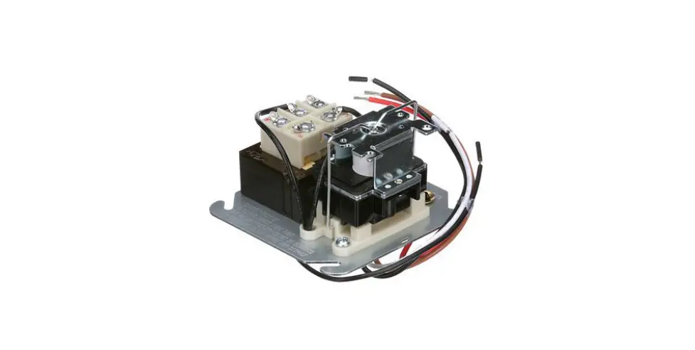
Relays and Transformers 90-112 Thru 90-130 Fan Control Center Specifications Manual
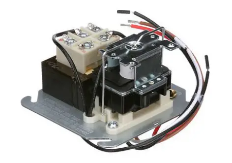
Transformer and relay combination for easy installation on a 4″ X 4″ junction box.
FEATURES
- Line voltage connections pre-wired
- Energy limiting Class II transformer design
- Color coded pre-stripped leads
- Low voltage connections on terminal board
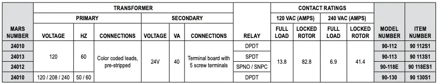
SPECIFICATIONS
UR/CUR File Number …………………………………………………………………………………….E73641
REPLACEMENT RELAY FOR FAN CONTROL CENTER

90-112 THRU 90-130 FAN CONTROL CENTER
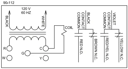
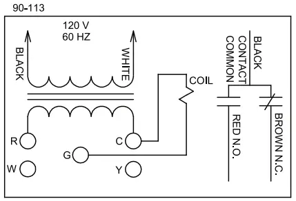
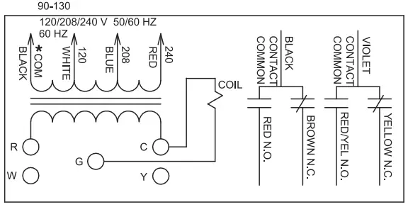
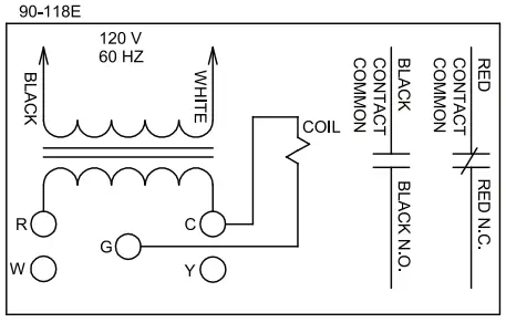
When the fan relay transformer is energized and the thermostat completes the connection from R to G the fan relay coil energizes. Line voltage power applied to contact common path travels to selected blower speed tap. Additional terminal Y and W are isolated tie point terminals to connect thermostat wiring to compressor and furnace (if required).
NOTE: Record the lead wire color with its corresponding terminal for future reference. Unused transformer input leads must be insulated.
* Black is common with respect to transformer winding, not external circuit.
Relays and Transformers 90-112 Thru 90-130 Fan Control Center Specifications Manual – Download [optimized]
Relays and Transformers 90-112 Thru 90-130 Fan Control Center Specifications Manual – Download


 Relay Switch Instruction Manual")


