![]()
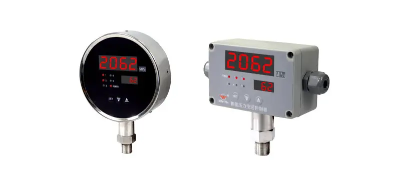
Intelligent digital/light column display controlling instrument
OPERATING MANUAL
WIDE PLUS PRECISION INSTRUMENTS CO., LTD.
NO: SOO1110418
Brief introduction of product
This series products have adopted surface packageing technology, which has greatly improved anti-interference capability, and have display, control, transmision communication functions and universual signal input. Through changing inner parameter can realize the switch of any signal type in table 1. They are widely used in many fields such as electric power, metallurgy, chemicals, petrochemicals, papermaking, printing and dyeing, brewage, tobacco, and space base and so on.
Main technical parameters
2.1 Type and code for input signal see table 1:
| Code | Type | Measuring range | Resolution | Equip sensor /transmitter | Input impedance |
| 1 | B | 400-1800°C | 1°C | Pt-rhodium 10 Pt-rhodium6 thermocouple | |
| 2 | S | 0-1600°C | 1°C | Pt-rhodium10 —Pt thermocouple | |
| 3 | K | 0-1300°C | 1 °C | Nichromenickel Si thermocouple | ≥1M Ω |
| 4 | E | 0-1000°C | 1 °C | Nichrome Cuni thermocouple | |
| 5 | T | 0-320.0°C | 0.1°C | Cu Cuni thermocouple | |
| 6 | J | 0-1200°C | 1°C | Fe Cuni thermocouple | |
| 7 | Wre 3-25 | 0-2300°C | 1°C | Wre3 Wre25 thermocouple | |
| 8 | Pt100 | -200-650°C | 1°C | Pt thereto resistance 12„-100 | ≥10kΩ |
| 9 | Pt 100.1 | —199.9-320.0°C | 0.1°C | Pt thereto resistance R„= too | |
| 10 | Cu50 | —50.0-150.0°C | 0.1°C | Cu thereto resistance 120=50 | |
| 11 | 0 ∼20mV | — 1999∼9999 | Highest µ | Pressure sensor | ≥1M Ω |
| 12 | 4∼20mA | Highest µ | DDZ—III transmitter | ≤250 Ω | |
| 13 | 0∼10mA | Highest µ | DDZ— II transmitter | ||
| 14 | 1∼5V | Highest | DDZ— III transmitter | ≥4.7MΩ | |
| 15 | 0∼5V | Highest | DDZ— II transmitter | ||
| 16 | 0∼20mA | Highest µ | DDZ— II transmitter | ≤250Ω | |
| 17 | 30∼350 II | Highest 2. 6m 0 | remote pressure gauge | ≥ 10k Ω | |
| 18 | Special signal | Specified by user (please supply signal type, division number or corresponding fonnula) | |||
| 19 | 4∼20mA evolution | — 1999∼9999 | Highest µ | DDZ— III flow transmitter | ≤ 250 Ω |
| 20 | 0∼10mA evolution | Highest µ | DDZ— II flow transmitter | ||
| 21 | 1∼5V evolution | Highest | DDZ— III flow transmitter | ≥ 4. 7MΩ | |
| 22 | 0∼5V evolution | Highest | DDZ— II flow transmitter | ||
Note: if choose 0∼5V evolution signal input, can not switch to 1∼5V signal input.
2.2 Measuring accuracy: digital display ±0.5%FS±1 character; light column 1%FS I line
2.3 Temperature compensation scope: 0 50
2.4 Ambient condition: working temperature0 50 , relative humidity 85%. Avoid using in occasions with corrosion and flammable gas
2.5 Display mode: single/double screen four-digit digital display + LED state indication+ light column display (can be choosen)
2.6 Switch quantity output: every output point can be set to upper/lower limit control or alarm and with return difference arbitrarily Relay output: Contact capacity (resistive load): AC220V/5A; DC24V/5A
Silicon controlled rectifier zero-crossing trigger pulse output(SCR): can trigger 600V/100A silicon controlled rectifier
Solid-state relay control signal output(SSR): output DC 9V/30mA
SCR zero-crossing trigger pulse output: BCR 600V/5A
2.7 Analog quantity output:
DC 0 10mA output, load resistance 1.5k
DC 4 20mA output, load resistance 750
DC 0 5V output, load resistance 250K
DC 1 5V output, load resistance 250K
2.8 Communication output: standard serial communication interface RS-485 or RS-232, Baud rate: 1200 9600bps, user set freely
2.9 Feed output: DC24V, load 30mA
2.10 Power supply mode:
Linear power AC 190 240V, power 5W, weight 420g
AC/DC power 90 260V, power 4W, weight 260g
AC/DC power 20 30V, power 4W, weight 260g
Operation
3.1 Explanation of the intrument panel
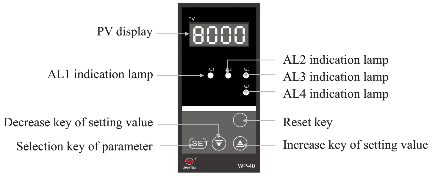
3.1.1 single-Screen display (take 48 x 96 for example)
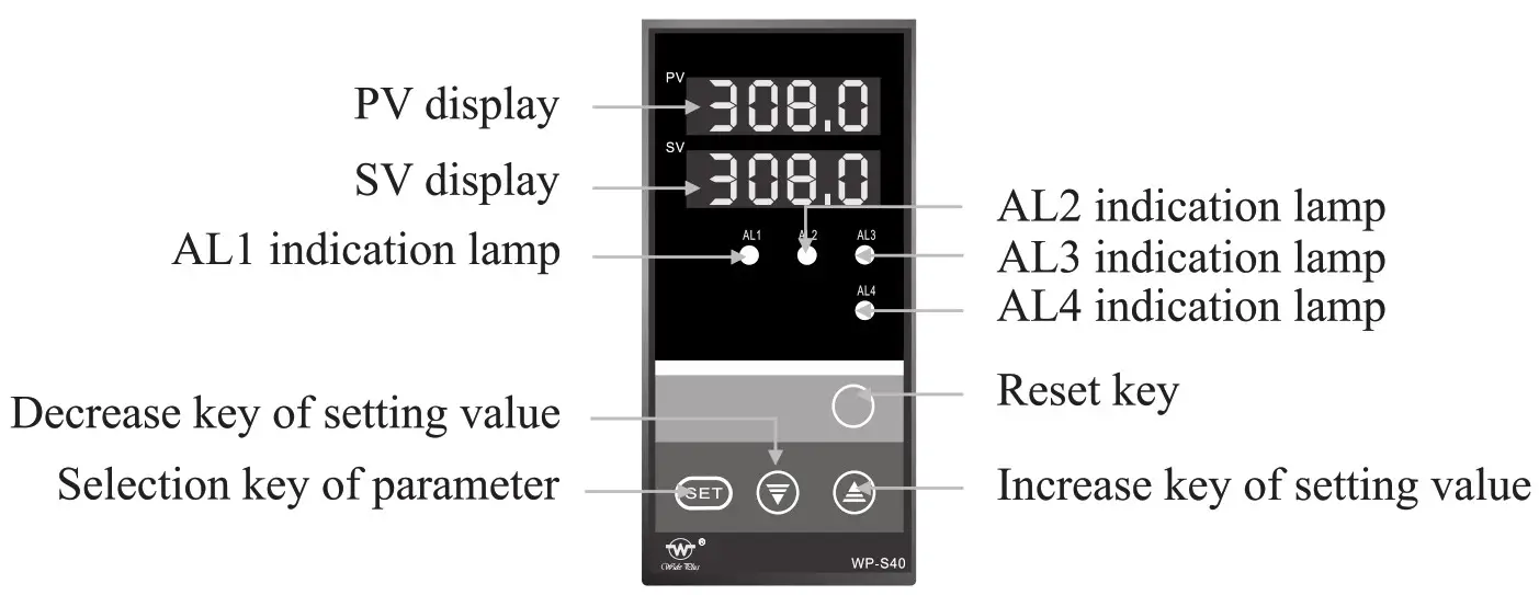
3.1.2 double-screen display (take 48 x 96 for example)
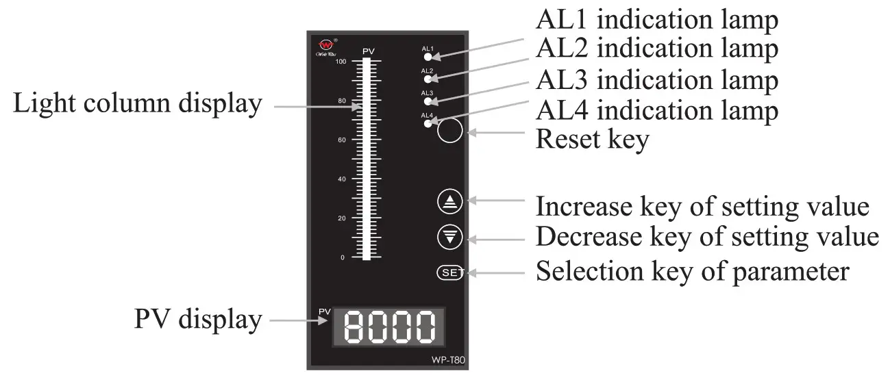
3.1.3 Single-screen and single light column dispaly (take 80 x 160 for example)
3.1.4 Explanation of each parts for instrument, see table 2:
| Name | Content | |
| Display | PV display | Display measured value Under parameter setup state, it shows parameter symbol or setting value |
| SV display | Display control target value Under parameter setup state, it shows parameter setting value | |
| Light column display | It displays corresponding percentage of measured value | |
| Operation key | SET selection key of parameter setup | Setting value which had been modified may be recorded. The mode of parameter setup may be changed in order. May change display or set parameter mode |
| ∇ Decrease key of setting value | When modifying set value, it is used to decrease value. Pressed continuously, it will automatically quick subtract 1 | |
| Δ Increase key | When modifying set value, it is used to increase value. Pressed continuously, it will automatically quick add 1. | |
| Reset key | For clear program (self-check), (the panel does not mark) | |
| Indicating lamp | AL 1 | When first control or alarm is ON, red lamp lights. |
| AL2 | When second control or alarm is ON, green lamp lights. | |
| AL3 | When third control or alarm is ON, red lamp lights. | |
| AL4 | When fourth control or alarm is ON, green lamp lights. | |
3.2 Engineering parameter setup (first-level parameter)
Under the display state of PV measured value display, presses SET key, the instrument will enter engineering parameter setup state. Only when CLK =00 or 132, engineering parameter can be modified. Press SET key to confirm after first-level and secondary parameter is modified. Please notice that the instrument parameter have someplace not give show because of instrument’s different functions. Engineering parameter setup see table 3:
| Symbol | Name | Setting range | Explanation |
| CLK | Set parameter lock | CLK=00, 132 | Unlock(set engineering parameter can be modified) |
| CLK#00 132 | Lock (set engineering parameter cannot be modified) | ||
| CLK=132 | Enter users parameter (secondary parameter) setup |
| Symbol | Name | Setting range | Explanation | ||
| AL 1 | The first control or alarm value | _1999_9999 | Ex-factory setting value 200 | ALI , AL2, AL3, Al4 control / alarm mode is set by SL2, SL3, SI4′ S15 respectively, see table 4 | |
| AL2 | The second control or alarm value | _1999_9999 | Ex-factory setting value 100 | ||
| AL3 | The third control or alarm value | _1999_9999 | Ex-factory setting value 150 | ||
| AL4 | The fourth control or alarm value | _1999_9999 | Ex-factory setting value 50 | ||
| AH1 | The first control or alarm return difference value | 9999 | Ex-factory setting value 2 | ||
| AH2 | The second control or alarm return difference value | 9999 | Ex-factory setting value 2 | ||
| MB | The third control or alarm return difference value | 9999 | Ex-factory setting value 2 | ||
| AH4 | The fourth control or alarm return difference value | 9999 | Ex-factory setting value 2 | ||
| DIP | Choose the SV display content (double-screen display instrument) | DIP) | Display division number | Ex-factory setting value 2 | |
| DIP=1 | Display AL 1 setting value | ||||
| DIP=2 | Display AL2 setting value | ||||
| DIP-3 | Display AL3 setting value | ||||
| DIP=4 | Display AL4 setting value | ||||
| DIP-5 | Display all value alternately | ||||
Note 1 Lower limit control or alarm: output when the PV is below the setting value, stop output when the PV is above the setting value + return difference value. Upper limit control or alarm: output when the PV is above the setting value, stop output when PV value is below the setting value—return difference value.
Note 2: As the different alarm number, the settings which alternately display each setting value may have corresponding modification.
3.3 Users parameter setup (secondary parameter)
Warning! Non-engineering design personnel are not allowed to modify the following parameters, or it will make the instrument control mistake!
Under the display state of PV measured value display, presses SET key to set CLK=132, first press SET does not release and press increase key again, after 5 seconds, can enter into users parameter setup. Users parameter setup are as table 4:
| Symbol | Name | Setting range | Explanation | ||
| SLO | Input division number | 0—22 | Choose type for instrument input division number, see table I | ||
| SL I | Set PV/SV decimal point | SLID | No decimal point | ||
| SL1=1 | Dicimal point located at ” the ten ‘ s place ‘ (display X X X.X) | ||||
| SLI=2 | Dicimal point located at ” the hundred’s place ” (display X X.X X) | ||||
| SL 1=3 | Dicimal point located at ” the thousand’s pla e ‘ (displayX.X X X) | ||||
| SL2 | First control or alarm mode | SL2 ,1 | No control or alarm | Ex-factory sets 2 | |
| SL2=1 | Lower limit control or alarm | ||||
| SL2=2 | Upper limit control or alarm | ||||
| SL3 | Second control or alarm mode | SL3 (.1 | No control or alarm | Ex-factory sets 1 | |
| SL3=1 | Lower limit control or alarm | ||||
| SL3=2 | Upper limit control or alarm | ||||
| SL4 | Third control or alarm mode | SL40 | No control or alarm | Ex-factory sets 2 | |
| SL4=1 | Lower limit control or alarm | ||||
| SL4=2 | Upper limit control or alarm | ||||
| SLS | Fourth control or alarm mode | SL5,1 | No control or alarm | Ex-factory sets 1 | |
| SL5=1 | Lower limit control or alarm | ||||
| SL5=2 | Upper limit control or alarm | ||||
| SL6 | Choose cold-compensation | SL6-3 | Internal cold-compensation | Ex-factory sets 0 | |
| SL6=1 | External cold compensation | ||||
| SL7 | Flash alarm | SL7) | No flash alarm | Ex-factory sets 0 | |
| SL7=1 | Have flash alarm | ||||
| SL8 | Choose alarm function | Units placed | No alarm delay function | Ex-factory sets 24 | |
| Units place =1-9 | Alarm delay 0.5 X setting value (second), then output | ||||
| Ten’s place4 | according sensor is power off, control or alarm cording to primary setup mode. | ||||
| Ten’s place-1 | n power off, control or alarm would reWthafnn tsheelsor srtlepo | ||||
| Ten’s place=2 | oW4untsensor is power off relieves control or alarm | ||||
| DE | Communication instrument device number | 0-254 | Device number should be unique in the same communication network, ex-factory sets 2 | ||
| BT | Instrument communication band rate setup | BT=2 | Band rate is 1200bps | When communication, baud rate of upper level machine and lower level machine should be set to accord. Ex-factory, sets 3 | |
| BT=3 | Band rate is 2400bps | ||||
| BT=4 | Band rate is 4800bps | ||||
| BT=5 | Band rate is 9600bps | ||||
| Symbol | Name | Setting range | Explanation | |
| Pb! | Display value zero offset | Fu” range | Set zero offset auantity of displayed value, Ex-factory sets-a | |
| KK1 | Display range scale | 0-1.999 times | Set the scale of display range, Ex-factory sets 1.000 times | |
| Pb3 | Ransmission output zero offset | 0–100.0 | Set zero offset of transmission output (see table 7) | |
| KK3 | Transmission output range scale | 0-1.200 times | Set range scale of transmission output (see table 7) | |
| on, | Lower limit of transmission output range | Full range | Set lower limit of transmission output,ex-factory setting value is the same as SLL | |
| OUH | Upper limit of transmission output range | Full range | Set upper limit of transmission output,ex-factory setting value is the same as SLH | |
| PVL | Set lower limit of flash alarm | Full range | When measured value is below the setting value, measured value flashes. There is this function when SL7=7, ex-factory value is the same as SLL | |
| Set lower limit of light column display | Full range | Set lower limit range value of light column display (light column table) | ||
| PVH | Set upper limit of flash alarm | Full range | When measured value is above the setting value, measured value flashes. There is this function when SL7=1, ex-factory value is the same as SLH | |
| Set upper limit of light column display | Full range | Set upper limit range value of light column display (light column table) | ||
| SLL | Lower limit of measuring range | Full range | Set lower limit range of input signal | Except resistance and couple type |
| SLH | Upper limit of measuring range | Full e range | Set upper limit range input signal | |
| SLU | Measured small signal removal | a ,,,„ ac, vr— a uv.vm | SLU is the percentage of measuring signal range, It is used only when measured signal extracts. As measured value is less than range (%), it displays 0. | |
3.4 Operating method
3.4.1 Switching of input signal: modify users parameter SLO, see table 1 for details.
3.4.2 Set of PV/SV decimal point: modify user parameters SL1, see table 4, PV/SV decimal point of thermocouple, thermo resistance cannot be set, decimal point of the Pt100.0 and Cu50 is fixed to be one place, others have not decimal point. Standard signal can be set.
3.4.3 Set of lower limit control or alarm value: set ALX value to be start point of lower limit value, ALX+AHX is stop point of lower limit value (X means
1, 2, 3, 4, below is alike), see table
3. 3.4. 4 Set of upper limit control or alarm value: set ALX value to be stop point of upper limit value, ALX-AHX is start point of upper limit value, see table 3. 3.4.5 Set of upper/lower limit control mode: modify user parameters SL2 —SL5, the detail see table
4. 3.6 Set of internal/external cold-compensation and light column display: modify user parameter SL6, see table 4, if users choose external cold compensation it should be connected Cu 50 sensor
3.4.7 Control/alarm state set when a sensor was disconnected: modify user parameter SL8, see table 4. Control or alarm output according to primary setting mode when the ten’ s place of SL8 setting value is 0, that is when the instrument shows OH, upper limit has output, when it shows OL, lower limit has output; The instrument will keep disconnection state when it displays 1, that is when the instrument display Err it will remain initial control or alarm; the instrument will remove control or alarm output when it is 2, that is, when instrument displays Err it has not control or alarm output.
3.4.8 Set of device number and baud rate: Instrument’s device number should be unique in the RS485 communication. Band rate of upper-level machine and the lower-level machine should be accord, see table 4 for user parameter DE and BT.
3.4.9 Set of transmission output range: modify user parameter OUL and OUH, see table 4, its span should be less than or equal to display range. When the sensor was disconnected, displays OH means transmitting output maximum or displays OL means output minimum.
3.4.10 Set Upper and lower limit of light column display: See table 4 for user parameter PVL and PVH.
3.4.11 Set measured small-signal removal: in the field of measuring flow, when flow is smaller, measured value undulation is bigger, and error is bigger. the usual method is small signal removal. User parameter (table 4) SLU meanings shows % of range, that is, when (measured value =range) X % ≤ .SLU setting value, the instrument shows 0. Instrument has small signal removal function only when it with evolution function.
3.4.12 Methods to return to measure state:
•Manual return: Under parameter setting mode, pressing SET key for 5 seconds the instrument will automatically return to measured value display state.
•Automatic return: Under parameter setting mode, does not press any key for 30 seconds, the instrument will automatically return to measured value display state.
•Reset return: Under parameter setting state, pressing RESET key, the instru-ment will enter measured value display after self-check again.
3.4.13 Display content of thermo-resistance, thermocouple disconnection instru-ment: when the ten’ s place of SL8 parameter is 0, instrument display OL or OH; when the ten’ s place of SL8 is not 0, instrument display Err.
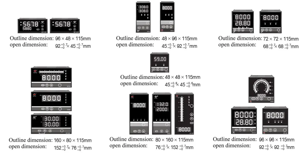
Installation and operation
This instrument adopts standard cassette-inserted type structure, please gently push it into the dial.
4.1 Outline and open dimension (unit: mm)
4.2 Wiring (Subject to enclosed wiring diagram)
4.2.1 48×48 wiring diagram
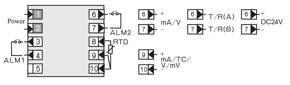
4.2.2 72×72 series wiring diagram
Note: when there is communication, transmitting output is at 6 and 7 terminals, when there is not communication, transmitting output is at 8 and 9 terminals.
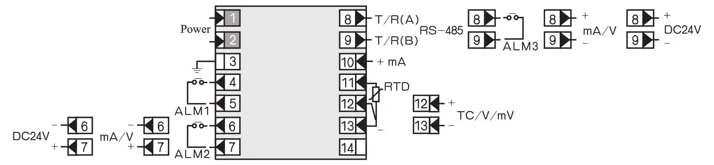
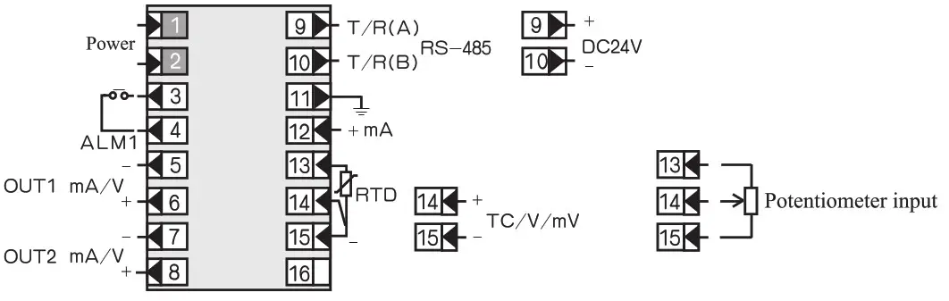
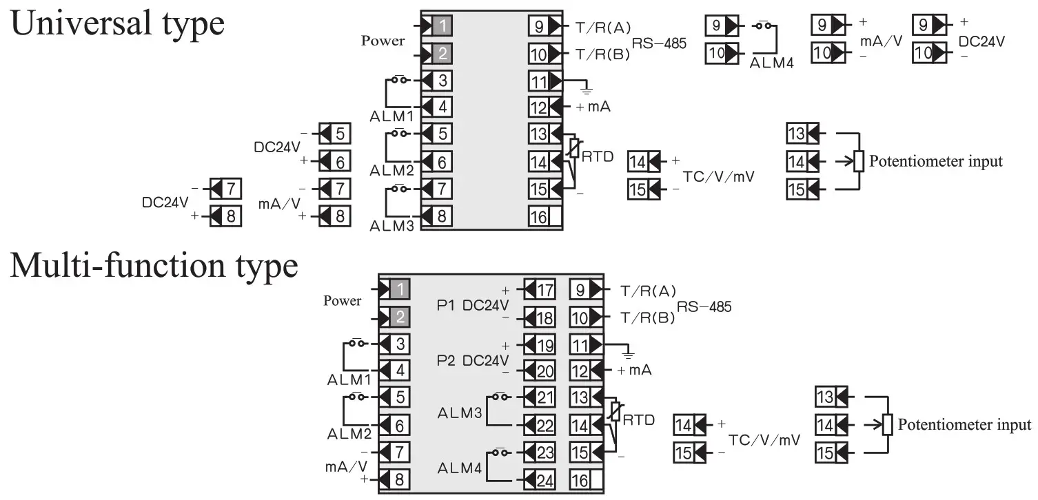
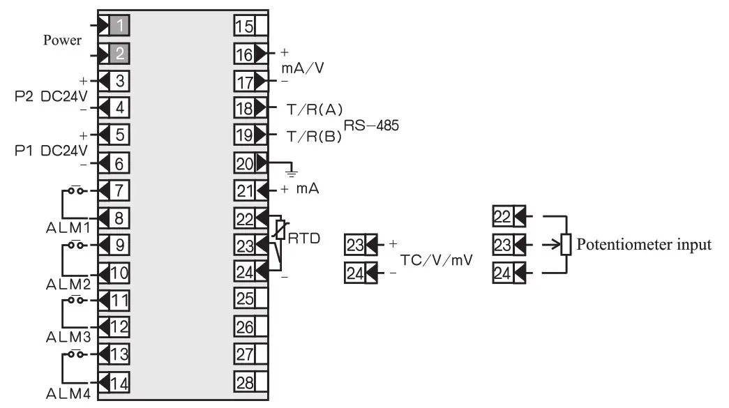
4.2.3 96×48, 48×96 wiring diagram
Universal type
Note: when there is communication, transmitting output is at 7 and 8 terminals, when there is not communication, transmitting output is at 9 and 10 terminals.
Double transmission type
4.2.4 96×96 wiring diagram
Double transmission type
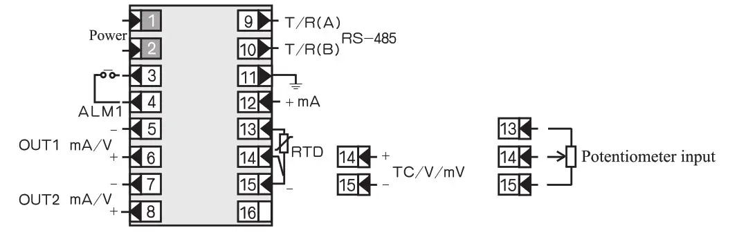
4.2.5 160×80, 80×160 wiring diagram
Universla type
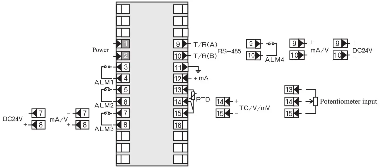
Multi-function type
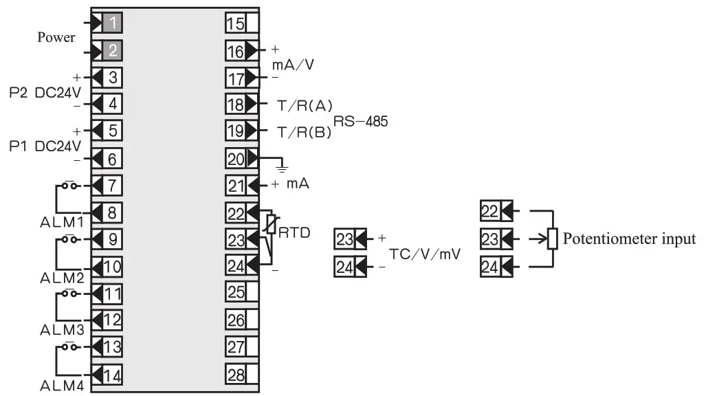
Double transmission type
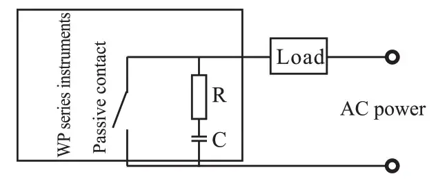
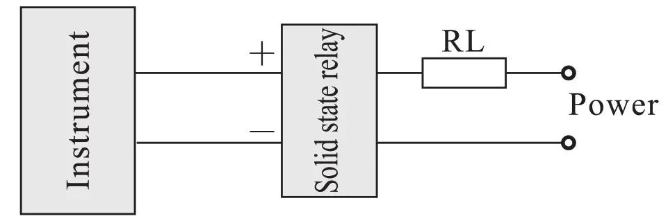
* Note: In order to absorb the peak interference of induction load, relay passive contact output of WP series instruments is connected with RC network at the two ends of contact. As the following figum, when load current is small (such as < 2OmA), if abnomal situations arising, can remove the resistance or capacitance in the RC network to eliminate abnormal situations.
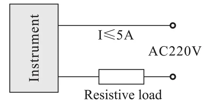
 4.2.6 Control/alarm output is wiring of SCR, SSR and SCR zero-crossing trigger pulse
a.Wiring of bidirectional controlled rectifier (BCR).
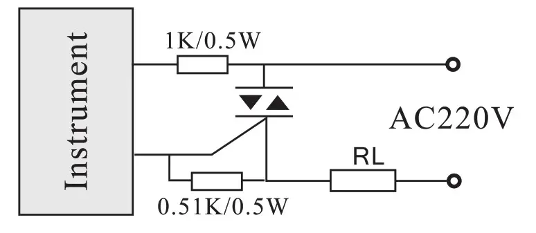 Note: SCR should be adopted protective measures
b.Wiring of two reversed parallel triggered by SCR
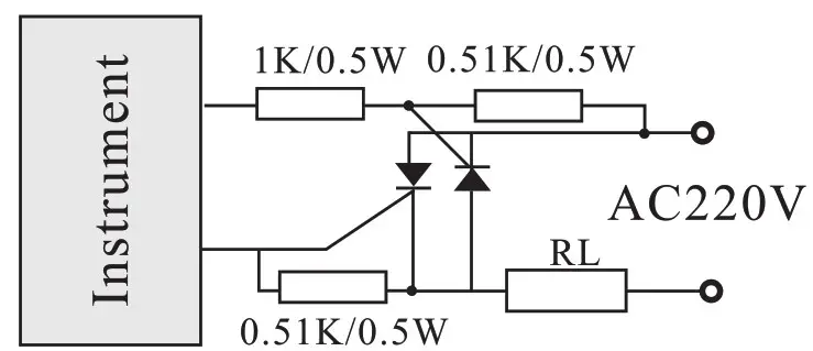 Note: SCR should be adopted protective measures.
c. Wiring of SSR control solid state relay
d.Wiring of SCR zero-crossing trigger pulse output
 Note: please refer to enclosed wiring diagram for the concrete connection terminal.
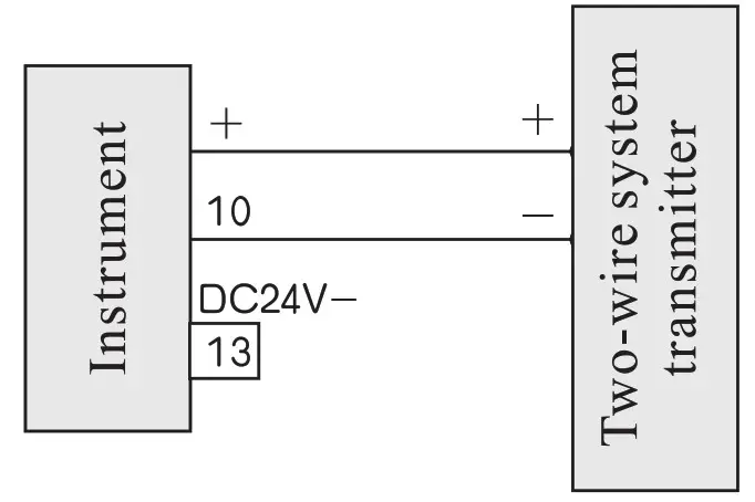
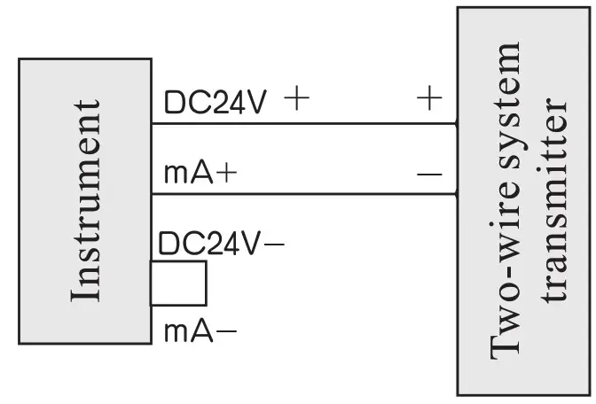
4.2.7 Wiring of feed and two-wire system transmitter
a.72 X 72 wiring diagram
b.96 X 48, 48 X 96, 96 X 96, 160 X 80, 80 X 160 wiring diagram
 Modification of transmission output signal
 Modification of transmission output signal
Short-circuit ring which is designed on the transmission output board may chang the output of current or voltage according to method of table 6. User parameters may be set by method of table 7, Pb3 and KK3 may change the upper/lower range of output signal.
| DC current output | DC voltage output | |
| Short-circuiting ring state |  |  |
| Signal output end voltage, resistance | voltage: 20—30V resistance: infinite | voltage: 0-,-.10V resistance: 250-5000 or infinite |
Signals Pb13, Pb23, Kk13, Kk23 output different ranges may be set according to the following table: Table 7
| 0 ∼ 10mA | 4∼ 20mA l -6V | 0∼ 20mA 0–#5V/0–#10V | |
| Pb13, Pb23 | 0.0 | 20.0 | 0.0 |
| KK13, KK23 | 0.500 | 1.000 | 1.000 |
Calibration of display transmit measure
6.1 Calibration of display range: When error exists between H/L limit display range and actual range, range can be adjusted by modifing Pbl and KK1, the details are as the following method:
ICIC1= scheduled range ÷ display range X initial Kk 1 (scheduled range: SLH-SLL)
Pbl= lower limit of scheduled range—lower limit of display range X KU +initial Pbl
For example: a DC current 4-20mA input instrument, measuring rang is
200-1000Kpa, while calibration, find that when input 4mA, displays
-202, when input 4mA, displays 1008. (Initial Pb171, initial KK1=1)
According to the formula:
KK1=scheduled range ÷ display range X initial KK1
= [1000- (-200)] ÷ [1008+202)] X 1
= 1200+1210 X 1 0.992
Pbl= lower limit of scheduled range-lower limit of display range X KK1+ initial Pbl= -200- (-202 X 0.992) +0=0.384≈0.4
Set: Pb17,1.4, KK1 .992
6.2 Calibration of transmission range: When error exist between H/L limit transmission output and actual range, range can be adjusted by modifying Pb3 and
KK3, the details are as the following method:
KK3= scheduled output range ÷ actual output range X initial KK3 (Scheduled output range: OUH-OUL)
Pb3 = scheduled lower limit output-actual lower limit output X Kk3 + initial Pb3
For example A DC current signal 4″-20mA input instrument, measuring range is -200-1000Kpa, transmission output is 4-20mA; While calibration, find that the instrument display is very accurate; when input 4mA and 20mA, the instrument output 3.9mA and 20.1mA respectively, set initial instrument Pb3=20.0, KK3=1.000.
According to the formula:
KK3=scheduled output range ÷ actual output range X initial Kk3
= (20-4) ÷ (20.1-3.9) X 1.000
= 164-16.2 X 14.988
Pb3= scheduled lower limit output-actual lower limit output X Kk3 + initial Pb3
= 4-3.9 X 0.988 +20.0 =20.1
Set: Pb3=20.1, Kk3=0.988
Note: Before calibrating transmission output, first ensure that the display is correct or not, Pbl, Pb3 modified value precise to one digit behind decimal point.
Maintenance and guarantee of quality
7.1 Under the normal condition, special maintenance is unnecessary for the instrument; please notice to damp-proof.
7.2 For the failures caused by the quality problem of the products, implement ” three guarantees ” within 18 months after leaving the factory.
Enclosed accessories
8.1 One operating manual
8.2 One copy of examination certificate and maintenance card
8.3 A set of fixed buckles (except 160 X 80, 80 X 160 outline instrument)
8.4 Various unit’s tags label, each one sheet.
8.5 With communication instrument and one testing floppy disk
Type spectrum table for intelligent digital/light column display controlling instrument
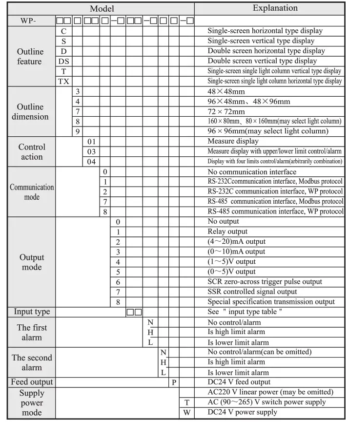
* Model for example:
WP-C801-00-08-N
WP-C403-01-12-HL
WP-T804-81-08-2H2L
* Note: Only need to set the secondary parameter if modifying input signal, see table 1, if users have no special requirement, then the instrument does not have input signal of (30–350) Q .
* Note 1: Outline dimension 48 X 48mm, may choose alarm + transmission + 485 communication + feed functions, which cannot be more than 2 functions; such as, may choose upper limit alarm + lower limit alarm or select communication + transmission, or choose alarm + transmission etc.(below the same); can not choose at the same time transmission and feed; no double screen display; no (22-26)VAC/DC power supply.
* Note 2: Outline dimension 72 X 72mm, choose alarm + transmission+485 communication +feed, which cannot be more than 3 functions; There could not choose at the same time transmission and feed;
* Note 3: two channels transmitting output, only have one alarm, no feed output; there is not (22-26)V AC/DC power supply.
Model example: Some project needs a control temperature instrument with the following functions: single-screen display, the communication mode with the upper-level machine is RS-485, convert the field temperature into standard DC (4-20)mA signal output, additionally with two relay control output, sensor is K type thermocouple, outline dimension is 96 X 96mm. Selected model is: WP-C903-82-03-HL-T
WIDE PLUS PRECISION INSTRUMENTS CO.,LTD.
Te1:2887 3802 Fax:2887 2479 L
E-mail: [email protected] http://www.wideplus.com


