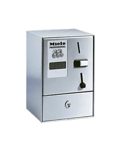
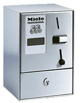
Miele C 4070 EUR WM Single Seat Payment Device
Payment device
Depending on the application, one of the following payment devices is required:
Parts required
| No. | Mat. no. | Designation |
| 05708610 | C 4060 WM 2 (single-unit payment device, mechanical coin acceptor unit for token no. 2) | |
| 10768520 | C 4060 WM 2 GL (single-unit payment device, mechanical coin acceptor unit for token no. 2, same key) | |
| 05709100 | C 4060 WM 2 SL (single-unit payment device, mechanical coin acceptor unit for token no. 2, including slot lock) | |
| 05708630 | C 4060 WM 8 (single-unit payment device, mechanical coin acceptor unit for token no. 8) | |
| 10768540 | C 4060 WM 8 GL (single-unit payment device, mechanical coin acceptor unit for token no. 8, same key) | |
| 05709110 | C 4060 WM 8 SL (single-unit payment device, mechanical coin acceptor unit for token no. 8, including slot lock) | |
| 05708640 | C 4060 WM 9 (single-unit payment device, mechanical coin acceptor unit for token no. 9) | |
| 10768560 | C 4060 WM 9 GL (single-unit payment device, mechanical coin acceptor unit for token no. 9, same key) | |
| 05709130 | C 4060 WM 9 SL (single-unit payment device, mechanical coin acceptor unit for token no. 9, including slot lock) | |
| 05708760 | C 4065 0.50 Euro (single-unit payment device, mechanical coin acceptor unit for € 50 cent coins) | |
| 05708780 | C 4065 0.50 Euro GL (single-unit payment device, mechanical coin acceptor unit for € 50 cent coins, same key) | |
| 07691030 | C 4065 1 Euro (single-unit payment device, mechanical coin acceptor unit for € 1 coins) | |
| 05708820 | C 4070 Euro WM (single-unit payment device, with electronic coin acceptor unit for € 2/1/0.50/0.20/0.10 coins and tokens no.: 2/8/9.) |
All kits include an accessory pack and M3 hex nut.
Included parts
| No | Mat. no | Designation |
| 1 | 05728441 | M3 hex nut with pressed-on washer |
C 4060, C 4065, C 4070 accessories include the following parts:
| No. | Mat. no. | Designation |
| 4 | 00104451 | Bolt M6 x 12 |
| 8 | 06531560 | Galvanised washer B6.4 |
| 4 | 06531600 | M6 hex nut |
| 1 | 02174751 | Underlay |
| 1 | 01636052 | Cable strain relie |
| 4 | 00277671 | Bolt M6 x 25 |
| 2 | 06543690 | Raised-head self-tapping screw 4.2 x 9.5 |
| 2 | 06543690 | Raised-head self-tapping screw 4.2 x 9.5 |
Depending on the version, one of the following payment devices is included:
| No. | Designation | |
| 1 | 05703410 | C 4060 RRP 220–240 V 50–60 Hz (WM 2, 2 SL, 8, 8 SL, 9, 9 SL) |
| 1 | 10768930 | C 4060 same key AC 220–240 V 50–60 Hz RRP (WM 2 GL, 8 GL, 9 GL) |
| 1 | 05703390 | C 4065 RRP 220–240 V 50–60 Hz (€ 0.50, € 1.00) |
| 05710050 | C 4065 RRP € 0.5 Same key 220–240/50–60 (€ 0.50) | |
| 1 | 05703350 | C 4070 RRP 220–240 V 50–60 Hz (€ 2/1/0.50/0.20/0.10 + WM 2/8/9) |
Depending on the version, one of the following coin acceptor units is installed:
| No. | Mat. no. | Designation |
| 1 | 05834301 | Coin acceptor unit WM 2 mat. no. 1699370 |
| 1 | 05834321 | Coin acceptor unit WM 8 mat. no. 0011729 |
| 1 | 05834331 | Coin acceptor unit WM 9 mat. no. 0011726 |
| 1 | 05686692 | Coin acceptor unit EUR 0.50 |
| 1 | 05842342 | Coin acceptor unit EUR 1.00 |
| 1 | 06109801 | Electronic module EUR 2/1/0.5/0.2/0.10 |
Depending on the version, a number of one of the following tokens are included:
| No. | Mat. no | Designation |
| 01699370 | WM 2 24 x 1.8 Miele token | |
| 00011729 | WM 8 17 x 1.8 Miele token | |
| 00011726 | WM 9 25.5 x 1.8 token |
Depending on the version, a sticker for the control field is included:
| No. | Mat. no | Designation |
| 1 | Sticker |
For safety reasons, the connection cable must not exceed 2.5 m in length.
The “Miele Service Documentation (MSD)” service application is required when carrying out maintenance work on the appliance The safety instructions and warnings in the Miele Service Documentation (MSD) for the corresponding model must be observed.
Work on the appliance must be carried out in accordance with the work instructions.
Drilling template
The underlay also serves as a drilling template for the 4 fixing holes.
NOTE
The holes for fixing are re-drilled depending on the washing machine or tumble dryer model.![]() Observe the machine-specific instructions for drilling the holes
Observe the machine-specific instructions for drilling the holes
Drilling fixing holes
This part of the instructions only applies to the following models: PW 5065, PW 6055, PW 6065, PW 6080, PT 5135 C, PT 5136, PT 7135 C, PT 7136, PT 7186![]() Place the supplied underlay on the machine lid and align it with the edges of the machine lid with W = 35 mm and Z = 80 mm, see Fig. 1.
Place the supplied underlay on the machine lid and align it with the edges of the machine lid with W = 35 mm and Z = 80 mm, see Fig. 1.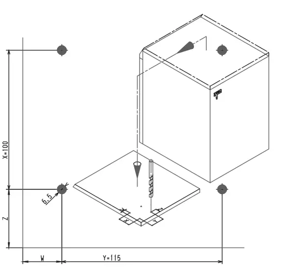
![]() Drill 4 holes with Ø 6.5 mm.
Drill 4 holes with Ø 6.5 mm.![]() Punch out the pre-punched hole for feeding through the cable on the rear panel of the machine
Punch out the pre-punched hole for feeding through the cable on the rear panel of the machine
This part of the instructions only applies to the following models: T 5200, T 5250
Additional parts required
| No. | Mat. no | Designation |
| 1 | 00090179 | Label (sticker to cover the sequential-circuit hole in the control panel) |
![]() Place the supplied underlay on the machine lid and align it with the edges of the machine lid with W = 60.5 mm and Z = 31 mm, see Fig. 2.
Place the supplied underlay on the machine lid and align it with the edges of the machine lid with W = 60.5 mm and Z = 31 mm, see Fig. 2.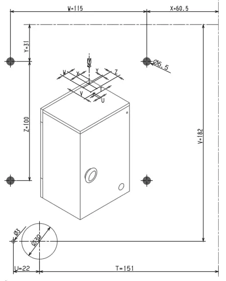
![]() Drill 4 holes with Ø 6.5 mm, see Fig. 2.
Drill 4 holes with Ø 6.5 mm, see Fig. 2.![]() Drill 1 hole with Ø 3 mm, see Fig. 2.
Drill 1 hole with Ø 3 mm, see Fig. 2.![]() Drill 1 hole with Ø 30 mm, see Fig. 2.
Drill 1 hole with Ø 30 mm, see Fig. 2.![]() Bridge sequential circuit contacts P3, P5 and P7.
Bridge sequential circuit contacts P3, P5 and P7.![]() Plug contact 9 to 13 and contact 17 to 21.
Plug contact 9 to 13 and contact 17 to 21.![]() Withdraw contacts 25 and 31 and bridge with plug connections.
Withdraw contacts 25 and 31 and bridge with plug connections.![]() Remove sequential circuit surge (9), see Fig. 4.
Remove sequential circuit surge (9), see Fig. 4.![]() Cover the drill holes in the control panel with stickers mat. no.: 00090179.
Cover the drill holes in the control panel with stickers mat. no.: 00090179.![]() Use the Ø 30 mm (10) hole for the connection cable with cable strain relief, see Fig. 4.
Use the Ø 30 mm (10) hole for the connection cable with cable strain relief, see Fig. 4.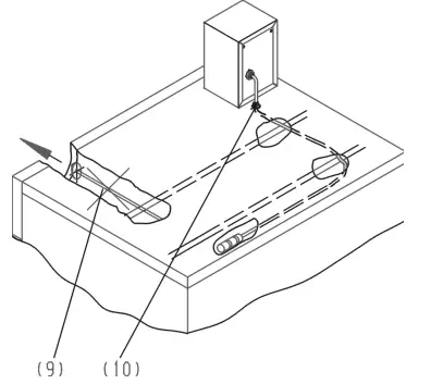
This part of the instructions only applies to the following models: T 6200, T 6250, T 6251![]() Place the supplied underlay on the machine lid and align it with the edges of the machine lid with W = 60.5 mm and Z = 31 mm, see Fig. 2.
Place the supplied underlay on the machine lid and align it with the edges of the machine lid with W = 60.5 mm and Z = 31 mm, see Fig. 2.![]() Drill holes with Ø 6.5 mm, see Fig. 2.
Drill holes with Ø 6.5 mm, see Fig. 2.![]() Drill hole with Ø 3 mm, see Fig. 2.
Drill hole with Ø 3 mm, see Fig. 2.![]() Drill hole with Ø 30 mm, see Fig. 2.
Drill hole with Ø 30 mm, see Fig. 2.![]() Use the Ø 30 mm (10) hole for the connection cable with cable strain relief, see Fig. 4.
Use the Ø 30 mm (10) hole for the connection cable with cable strain relief, see Fig. 4.
This part of the instructions only applies to the following models:
PT 7251, PT 7331, PT 8251, PT 8251 COP, PT 8253, PT 8255, PT 8331, PT 8331 COP, PT 8333, PT 8335, PT 8257, PT 8337
A Place the supplied rubber underlay on the machine lid and line it up with the edges of the machine lid with X = 60.5 mm and Y = 31 mm, see Fig. 3.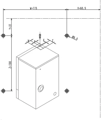
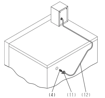
![]() Drill 4 holes with Ø 6.5 mm, see Fig. 3.
Drill 4 holes with Ø 6.5 mm, see Fig. 3.![]() Punch out the pre-punched hole for feeding through the cable on the rear panel of the machine.
Punch out the pre-punched hole for feeding through the cable on the rear panel of the machine.![]() Use the pre-punched hole for the connection cable (12) with cable strain relief (11), see 5.
Use the pre-punched hole for the connection cable (12) with cable strain relief (11), see 5.
This part of the instructions only applies to the following models: PW 6107, PW 6137, PW 6167, PW 6207![]() Place the supplied rubber underlay on the machine lid and line it up with the edges of the machine lid with X = 60.5 mm and Y = 31 mm, see 2.
Place the supplied rubber underlay on the machine lid and line it up with the edges of the machine lid with X = 60.5 mm and Y = 31 mm, see 2.![]() Drill 4 holes with Ø 6.5 mm, see Fig. 2.
Drill 4 holes with Ø 6.5 mm, see Fig. 2.![]() Punch out the pre-punched hole (1) for feeding through the cable on the top rear panel of the machine, see Fig. 6.
Punch out the pre-punched hole (1) for feeding through the cable on the top rear panel of the machine, see Fig. 6.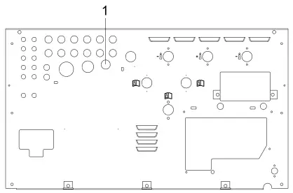
![]() Use the pre-punched hole for the connection cable with cable strain relief.
Use the pre-punched hole for the connection cable with cable strain relief.
This part of the instructions only applies to the following models: PW 413, PW 418, PW 811, PW 814, PW 818
![]() Place the supplied rubber underlay on the machine lid and align it with the edges of the machine lid with X = 60.5 mm and Y = 31 mm. This serves as the drilling template, see Fig. 2.
Place the supplied rubber underlay on the machine lid and align it with the edges of the machine lid with X = 60.5 mm and Y = 31 mm. This serves as the drilling template, see Fig. 2.![]() Drill 4 holes with Ø 6.5 mm, see Fig. 2.
Drill 4 holes with Ø 6.5 mm, see Fig. 2.![]() Punch out the pre-punched hole (1) for feeding through the cable on the top rear panel of the machine, see Fig. 7.
Punch out the pre-punched hole (1) for feeding through the cable on the top rear panel of the machine, see Fig. 7.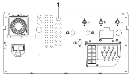
![]() Use the pre-punched hole for the connection cable with cable strain relief.
Use the pre-punched hole for the connection cable with cable strain relief.
This part of the instructions only applies to the following models: PW 413, PW 418, PW 811, PW 814, PW 8
![]() Place the supplied rubber underlay on the machine lid and align it with the edges of the machine lid with X = 60.5 mm and Y = 31 mm.
Place the supplied rubber underlay on the machine lid and align it with the edges of the machine lid with X = 60.5 mm and Y = 31 mm.
This serves as the drilling template, see Fig. 2.![]() Drill 4 holes with Ø 6.5 mm, see Fig. 2.
Drill 4 holes with Ø 6.5 mm, see Fig. 2.![]() Punch out the pre-punched hole (1) for feeding through the cable on the top rear panel of the machine, see Fig. 7.
Punch out the pre-punched hole (1) for feeding through the cable on the top rear panel of the machine, see Fig. 7.![]() Use the pre-punched hole for the connection cable with cable strain relief.
Use the pre-punched hole for the connection cable with cable strain relief.
Drilling fixing holes when replacing the payment device
This part of the instructions applies when replacing a C 5002 or C 5003 payment device with a C 4060, C 4065 or C 4070 payment device.![]() When replacing a C 5002, new fixing holes must be drilled in the machine lid, see Fig. 8.
When replacing a C 5002, new fixing holes must be drilled in the machine lid, see Fig. 8.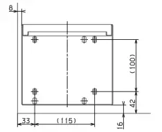
![]() When replacing a C 5003, new fixing holes must be drilled in the machine lid, see Fig. 9.
When replacing a C 5003, new fixing holes must be drilled in the machine lid, see Fig. 9.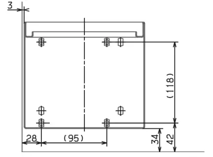
This part of the instructions only applies to the following models:
PWM, PDR generation
PWM 909, PWM 511, PDR 510, PDR 910 only
![]() Place the supplied underlay on the machine lid and align it with the edges of the machine lid with W = 35 mm and Z = 80 mm, see Fig. 1.
Place the supplied underlay on the machine lid and align it with the edges of the machine lid with W = 35 mm and Z = 80 mm, see Fig. 1.
PWM, PDR machines
![]() Place the supplied underlay on the machine lid and align it with the edges of the machine lid with W = 60.5 mm and Z = 31 mm, see 2.
Place the supplied underlay on the machine lid and align it with the edges of the machine lid with W = 60.5 mm and Z = 31 mm, see 2.![]() Drill 4 holes with Ø 6.5 mm.
Drill 4 holes with Ø 6.5 mm.
Installing the payment device
![]() Open the front panel of the payment device.
Open the front panel of the payment device.![]() Line up the underlay (1) over the pre-drilled holes, see Fig. 10.
Line up the underlay (1) over the pre-drilled holes, see Fig. 10.![]() Secure the payment device to the machine lid using the supplied fixing materials, see Fig. 10
Secure the payment device to the machine lid using the supplied fixing materials, see Fig. 10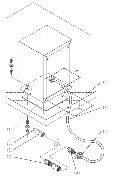
Connecting the payment device to an electrical supply
PWM, PDR generation
![]() Connect the connection cable to the Connector Box
Connect the connection cable to the Connector Box
All other machines
The hole for the cable guide is provided at different positions depending on the model.![]() Attach the cable strain relief to the cable.
Attach the cable strain relief to the cable.![]() Feed the cable into the machine through the opening provided.
Feed the cable into the machine through the opening provided.![]() Attach the cable with cable strain relief to the opening.
Attach the cable with cable strain relief to the opening.![]() Connect the connection plug (4) to the 7-pin socket in the machine (5), see Fig. 10.
Connect the connection plug (4) to the 7-pin socket in the machine (5), see Fig. 10.
An adapter may be required for payment devices C 4065 and C 4070. See the supplied information sheet “Notes for the electrical connection of payment devices” mat. no.:05688614
![]() If used, secure the adapter to the wiring harness with cable ties, see Fig. 10.
If used, secure the adapter to the wiring harness with cable ties, see Fig. 10.![]() For C 4065 and C 4070, disconnect the bridges (6) on the plug (5) in the machine in accordance with the information sheet, see Fig. 10.
For C 4065 and C 4070, disconnect the bridges (6) on the plug (5) in the machine in accordance with the information sheet, see Fig. 10.![]() For C 4060, disconnect the bridges (6) on the plug (5) in the machine in accordance with the wiring diagram, see Fig. 10.
For C 4060, disconnect the bridges (6) on the plug (5) in the machine in accordance with the wiring diagram, see Fig. 10.