
![]()
www.swisherinc.com
OWNER’S MANUAL
MODEL NO.
STARTING SERIAL #: L118-236001
RC14544BS
RC14544BS-CA
![]() IMPORTANT
IMPORTANT
Read and follow all Safety Precautions and Instructions before operating this equipment.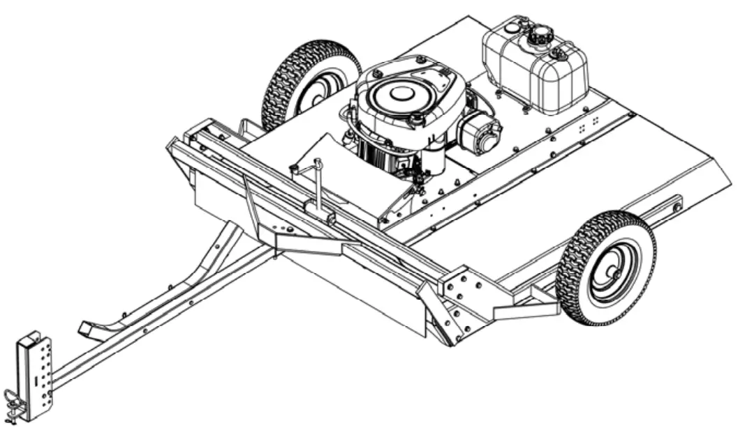 44” COUNTRY CUT TRAIL CUTTER
Assembly Operation Service and Adjustment Repair Parts
LIMITED WARRANTY
The manufacturer’s warranty to the original consumer purchaser is: This product is free from defects in materials and workmanship for a period of one (1) year from the date of purchase by the original consumer purchaser.
As required by CFR § 1060.120, the fuel system-related components, which have been certified to this equipment by SAI are to be free of defects in material and workmanship for a period of two (2) years from the date of purchase by the original consumer purchaser.
We will repair or replace, at our discretion, parts found to be defective due to materials or workmanship. This warranty is subject to the following limitations and exclusions:
| 1) Engine Warranty | All engines utilized on our products have a separate warranty extended to them by the individual engine manufacturer. Any engine service difficulty is the responsibility of the engine manufacturer and in no way is Swisher or its agents responsible for the engine warranty. The Briggs & Stratton Engine Service Hot Line is 1-800-233-3723. |
| 2) Commercial Use | This product is not intended for commercial use and carries no commercial warranty. |
| 3) Limitations | This warranty applies only to products, which have been properly assembled, adjusted, and operated in accordance with the instructions contained within this manual. This warranty does not apply to any product of Swisher that has been subject to alteration, misuse, abuse, improper assembly or installation, shipping damage, or normal wear of the product. |
| 4) Exclusions | Excluded from this warranty are normal wear, normal adjustments, and normal maintenance. |
In the event you have a claim under this warranty, you must return the product to an authorized service dealer. All transportation charges, damage, or loss incurred during
transportation of parts submitted for replacement or repair under this warranty shall be borne by the purchaser. Should you have any questions concerning this warranty, please contact us toll-free at 1-800-222-8183. The model number, serial number, date of purchase, and the name of the authorized Swisher dealer from whom you purchased the mower will be needed before any warranty claim can be processed.
THIS WARRANTY DOES NOT APPLY TO ANY INCIDENTAL OR CONSEQUENTIAL DAMAGES AND ANY IMPLIED WARRANTIES ARE LIMITED TO THE SAME TIME PERIODS STATED HEREIN FOR ALL EXPRESSED WARRANTIES. Some states do not allow the limitation of consequential damages or limitations on how long an implied warranty may last, so the above limitations or exclusions may not apply to you. This warranty gives you specific legal rights and you may have other rights, which vary from state to state. This is a limited warranty as defined by the Magnuson-Moss Act of 1975.
Thank you for choosing Swisher’s 44” Trail Cutter. Before operating your cutter, please read, understand and follow all of the safety precautions and other instructions explained in this manual. As with all power equipment, lawnmowers and cutters can be potentially dangerous if improperly used.
SAFETY PRECAUTIONS
 | This Safety Alert Symbol indicates important messages in this manual. When you see this symbol, carefully read the message that follows and be alert to the possibility of personal injury. |
Read this manual completely. This machine can amputate hands and feet, and throw objects. Failure to observe the following safety instructions could result in serious injury or death.
- Read the manual. Learn to operate this machine safely.
- Always disconnect the spark plug wire and place the wire where it cannot contact the spark plug, to prevent accidental starting of the engine when setting up, transporting,
adjusting, or making repairs. - Keep all shields and guards in place.
- Understand the speed, steering, and stability of this machine. Know the positions and operations of all controls before you operate this machine. Check all of the controls in a safe area before starting to work with this machine.
- Allow only responsible adults who are familiar with these instructions to operate this machine. Never allow children to operate this machine.
- Clear the area of objects such as rocks, toys, wire, etc. that can be picked up and thrown by the blade.
- Be sure the area is clear of other people before mowing. Be aware of the cutter’s discharge direction and do not point at anyone. Stop the machine if anyone enters the
cutting area. Children are often attracted to the machine and the mowing activity. Never assume that children will remain where you last saw them. Keep children under the watchful care of another responsible adult. - No riders!
- Do not put hands or feet near or under rotating parts.
- Do not mow in reverse. Always look down and behind before and during backing.
- Turn off the blades when not cutting. Before leaving the machine, turn off the blades and stop the engine.
- Watch for traffic when operating near or crossing roadways.
- Do not operate the cutter if it has been dropped or damaged in any manner or if the mower vibrates excessively. Excessive vibration is an indication of damage.
Repair cutter as necessary. - Dress properly. Do not operate the cutter when barefoot or wearing open sandals. Wear only solid shoes with good traction when cutting.
- Never allow operation by untrained persons.
- Do not operate the machine while under the influence of alcohol or drugs.
- Do not operate on slopes greater than 15 degrees.
- Never tamper with safety devices. Check their proper operation regularly.
- Stop and inspect the equipment if you strike an object. Repair, if necessary, before restarting. Never make adjustments or repairs with the engine running.
- Cutter blades are sharp and can cut. Wrap the blades or wear gloves, and use extra caution when servicing them. Do not operate at too fast a rate.
- Return lever to its vertical position to disengage blades.
- The braking system is applied when the blades become disengaged. It is designed to bring the blades to a quick stop (approximately 7 seconds). Each Trail Cutter brake
system has been set at the factory. For safety, the consumer should not alter the braking system.
ASSEMBLY
- Disengage the spark plug wire and place where it cannot make a connection.
- Refer to Fig 2 pg 11. Attach hitch assembly parts to the front of the mower. Insert 3/8-16 X 3 bolt through the center hole of the plate and secure with a 3/8-16 nut. Tighten the nut tight until the tube is clamped then back off ½ turn to allow the tube to pivot. Insert 3/8-16 X 3 bolt through one of the holes that form a circular pattern and secure with a 3/8-16 nut.
- The L hitch can be adjusted up or down to level the deck from front to back
- Check engine oil. All engines are filled with oil at the factory. Verify oil level and add if necessary before starting the engine. (See Engine Owner’s Manual)
- Verify fuel level and add if necessary before starting the engine. Electric Start Model (U1 battery not included):
- Check the battery. If the battery is put into service after the “month and year” of the date on the battery, it may need to be charged with a 12-volt battery charger for a minimum of 1 hour, but no more than 2 hours at a rate of 6 to 10 amps.
- Battery is located inside the battery box. Secure battery with rubber strap provided. Connect strap hooks into holes in the motor base. (See figure 14 – page 19)
- Attach battery cables to the battery, making sure to attach the red wire to the positive terminal first and the black wire to the negative terminal second.
- Reconnect spark plug wire.
- Refer to Owner’s Manual pg 5 for proper operating procedures.
OPERATING YOUR TRAIL CUTTER
| The operation of any mower can produce foreign objects to be thrown into the eyes, resulting in severe eye damage. Always wear certified safety glasses or wide-vision safety goggles over spectacles before starting any cutting machine and while operating such a machine. | |
 | The operation of any mower produces sound waves that are damaging to the human ear. Ear protection is recommended. |
| CAUTION! Tragic accidents can occur if the operator is not alert to the presence of children. Children are often attracted to the machine and the mowing activity. Never assume that children will remain where you last saw them. |
INTENDED USE
The 44” Trail Cutter is designed to clear dense areas of grass and cut saplings up to 3” thick on meadows and small estates. It is not intended to create a finish cut on lawns. our
Trail Cutter should be towed behind an ATV, golf cart, lawn tractor, or other approved vehicle. It is not recommended for speeds exceeding 5 MPH.
ATTACHING TRAIL CUTTER TO TOW VEHICLE
- Back vehicle up to the desired towing position.
- Offset the Trail Cutter to the side opposite the tow vehicle discharge (if any). This prevents the tow vehicle from throwing grass into the Trail Cutter engine.
- Using the 20268 hitch pin connect the hitch to the vehicle your machine will be towed with. Once attached adjust the level of the mower by sliding the hitch up or down within the L-hitch and inserting the pins through an alternative set of holes, securing with hairpins.
TRANSPORTING CUTTER
- Stop Trail Cutter.
- Place Trail Cutter deck in its highest position.
- When transporting without the use of a tow vehicle, remove the spark plug wire and place it where it cannot contact the spark plug.
STOPPING THE ENGINE
- Make sure the tow vehicle parking brake is set.
- Disengage cutting blades.
- Reduce engine to idle speed and allow the engine to run momentarily for cooling.
- Turn the key to the off position.
ENGAGING BLADES
Note: Do not attempt to start the unit with the T-handle console in the “ENGAGED” position.
- Engage blades by pulling down the T-handle lever into the horizontal position.
- Return lever to the vertical position to disengage blades. See Fig 8 pg 16.
- The braking system is applied when the blades become disengaged. It is designed to bring the blades to a quick stop (approximately 7 seconds). Each Trail Cutter brake system has been set at the factory the consumer should not alter any part of the brake system.
BREAKING IN YOUR CUTTER
- Set the vehicle parking brake and chock the wheels to prevent accidental rolling.
- While the engine is running, slowly engage blade control.
- In a safe environment, (i.e. no children or pets) allow blades to rotate and the engine to run at full throttle for 5 minutes, breaking in the belt for longer life.
- Disengage the blades and shut off the engine.
STARTING THE ENGINE
See engine manufacturer’s recommendations for the type and amount of oil and fuel used. Trail Cutters equipped with an electric start engine will need a battery (sold separately). Swisher recommends using a standard “U1” battery.
- Make sure the tow vehicle parking brake is set, the mower is level, and the blades are disengaged. The engine must be level to accurately check and fill oil. Do not overfill.
- Check spark plug wire, oil, and fuel.
- Check all electrical connections for the buildup of debris.
- Set engine idle to “CHOKE” position.
- Turn key to the “RUN” position.
- Pull rope with a single fluid motion.
- (12V models only) Turn key to the “RUN” position, then to the “START” position.
- Set engine idle at maximum RPM for best performance.
- Allow the engine to run a few moments before engaging blades.
![]() CAUTION: SHUT OFF THE CUTTER ENGINE AND REMOVE SPARK PLUG WIRE FROM SPARK PLUG BEFORE MAKING ANY ADJUSTMENTS TO THE CUTTER.
CAUTION: SHUT OFF THE CUTTER ENGINE AND REMOVE SPARK PLUG WIRE FROM SPARK PLUG BEFORE MAKING ANY ADJUSTMENTS TO THE CUTTER.
IMPORTANT: This engine is not equipped with a spark arrester muffler. It is a violation of California Public Resource Code Section 4442 to use or operate the engine on any forest-covered, brush-covered, or grass-covered land. Other states or federal areas may have similar laws.
FRONT TO BACK ADJUSTMENT
For best cutting results, the cutter deck should be parallel to the ground. To check the parallel adjustment, measure the distance from the bottom edge of the deck to both the front and rear of the deck. This adjustment is best done while the tow vehicle and Trail Cutter are connected.
- Remove hairpins NB127 from clevis pins 18842 so L-hitch 18829 can be repositioned.
- Raise or lower the hitch section to obtain a proper front-to-back adjustment.
- Insert clevis pins in the desired hitch position and secure with hairpins.
CUTTER HEIGHT ADJUSTMENT
- There is approximately 4” of height adjustment.
- Rotate height and adjust the crank handle in a clockwise direction to lower the mower deck. Rotate counterclockwise to lift the mower deck.
- Dense areas should be cut twice.
- Push handle down to lock height position.
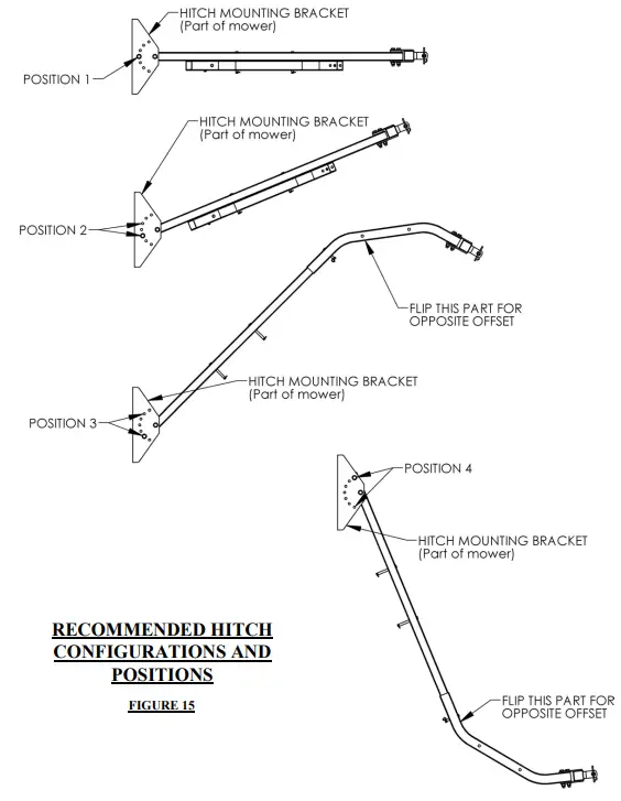
TOW HITCH OFFSET
- When offsetting the cutter do so to the side opposite the discharge of the tow vehicle if towing with a mower.
- Swisher recommends if the tow vehicle is equipped with a mid-mount mower to overlap the cut by approximately 6”. This may vary depending on mowing terrain, obstacles, and/or tow vehicle. Always keep safety the first priority.
- The mower on the tow vehicle should be set higher than the cutter.
STARTING TO CUT
- Adjust the cutting height.
- Double-check vehicle to cutter attachment.
- Start the mower engine and set the throttle to “FAST” for best cutting performance.
- Slowly engage the T-handle lever. See Fig 8 pg 16.
- Carefully mount the tow vehicle and start mowing at a slow travel speed.
STOPPING THE CUTTING SESSION
- Bring tow vehicle to a complete stop, set the parking brake, and disengage blades.
- Turn the key switch to the “OFF” position.
- Always remember to remove keys to avoid irresponsible usage.
SUGGESTED CUTTING PRACTICES
- Operate cutter engine at full throttle to assure the best cutting performance and maximum material discharge.
- Allow wet grass to dry. Wet grass will clump and collect under the mowing deck.
- Cutter should be started with a tow vehicle in low gear and increased only as safe mowing conditions permit. Cutting speed should not exceed 5 MPH.
- Cutting conditions and the types of grass will vary from place to place. You may find when cutting dense areas that the pressure of the wheel tracks may cause the grass to be pushed down and not effectively mowed. If this happens you may want to mow the area twice. Once the cutter is raised and the second cutting at the desired height. The second cutting should be at a right angle from the previous for best results.
- Reducing the travel speed will help cut dense growth. This allows the blades the time necessary to make its initial cut, and regain momentum to continue cutting. The engine may stall if you are moving too fast!
- Do not attempt to cut areas that the tow vehicle cannot maneuver through and/or slopes that you do not feel comfortable riding.
CUTTER MAINTENANCE
GENERAL RECOMMENDATIONS
The warranty on this cutter does not cover items that have been subjected to operator abuse or negligence. To receive full value from the warranty, the operator must maintain the unit as instructed in this manual. Some adjustments will need to be made periodically to maintain your unit properly.
BEFORE EACH SEASON
A new spark plug and clean air filter assure proper air-fuel mixture and help your engine run better and last longer.
• Replace the spark plug.
• Clean or replace the air filter.
• Check blades and belts for wear.
BEFORE EACH USE
• Check engine oil level. Do this twice to ensure an accurate reading.
• Check the condition of the air filter and clean or replace it if necessary.
• Check blade operation.
• Check for loose fasteners.
• Lubricate threads of adjustment rod P/N 4006. See Fig 3 pg 12.
DAILY MAINTENANCE
Make sure all nuts and bolts are tight and cotter pins and retainer springs are secure. Keep blades sharp. Observe all safety precautions.
BLADE CARE AND SERVICE
For best results cutter blades must be kept sharp. The blades can be sharpened with a few strokes of a file or grinding wheel. Do Not attempt to sharpen while on the cutter. Important: Replace blades that have been damaged or deeply nicked.
Important: Check blade and spindle hardware on a regular basis to make sure nuts are tight.
![]() CAUTION: DO NOT HANDLE CUTTER BLADES WITH BARE HANDS. CARELESS OR IMPROPER HANDLING MAY RESULT IN SERIOUS INJURY.
CAUTION: DO NOT HANDLE CUTTER BLADES WITH BARE HANDS. CARELESS OR IMPROPER HANDLING MAY RESULT IN SERIOUS INJURY.
GENERAL TROUBLESHOOTING
The unit is not cutting level.
- Level deck. Check the air pressure of all tires; make sure they are equal. See tires for maximum inflation.
- Without the engine running, make certain blades are installed identically.
The engine will not start.
- Disengage blades, turn the key switch to the “OFF” position, check the battery and all other electrical connections and inspect the spark plug and wire.
- Contact the engine manufacturer or a qualified mechanic.
Engine runs poorly.
- See engine manual.
- Check the throttle adjuster.
- Replace fuel, and check the fuel filter and fuel line.
- Check spark plug and gap.
Cutter bounces excessively while towing.
- Decrease tire pressure.
- Tow at a lower speed.
![]() IF PROBLEMS PERSIST HAVE A QUALIFIED MECHANIC SERVICE THE CUTTER. NEVER ATTEMPT TO MAKE AN ADJUSTMENT THAT YOU ARE NOT SURE IS CORRECT. DOING SO CAN CAUSE OTHER PROBLEMS.
IF PROBLEMS PERSIST HAVE A QUALIFIED MECHANIC SERVICE THE CUTTER. NEVER ATTEMPT TO MAKE AN ADJUSTMENT THAT YOU ARE NOT SURE IS CORRECT. DOING SO CAN CAUSE OTHER PROBLEMS. SAFETY AND OPERATIONAL DECALS
Replace decal immediately if damaged.

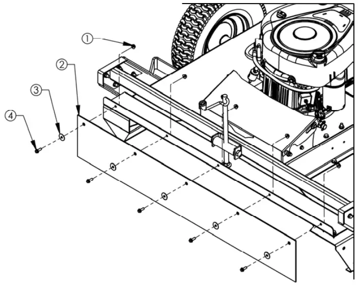
FRONT SKIRT ASSEMBLY
FIGURE 1
| Item # | Description | Part # |
| 1 | Nut – Serr Flange, 1/4-20 Grade 5 ZY | NB524 |
| 2 | Rubber Flapper | 10384 |
| 3 | Washer – Fender, 1/4X1 1/4OD Gr 2 ZY | 11520 |
| 4 | Bolt – Serr Flange, 1/4-20 X 3/4 GR5 ZY | NB690 |
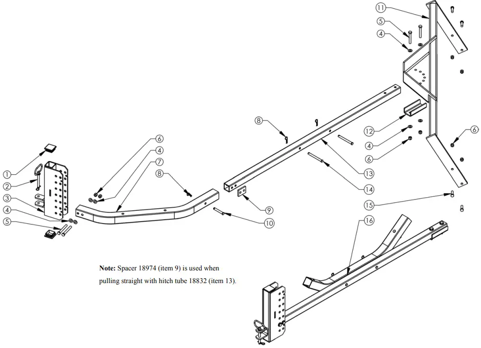
HITCH ASSEMBLY
FIGURE 2
| Item # | Description | Part # |
| 1 | Plug – 1.75 X 10⁻¹⁴GA Sq Tube | 18834 |
| 2 | Pin – Hitch, 3/8 X 3 w/ Hair Pin | 20268 |
| 3 | Weldment – L Hitch | 18829* |
| 4 | Washer – SAE Flat 3/8 | NB272 |
| 5 | Bolt – 3/8-16 X 3 | NB150 |
| 6 | Nut – Nyloc 3/8-16 | NB182 |
| 7 | Tube – Hitch Elbow | 18833* |
| 8 | Pin – Hair, #39 | NB127 |
| 9 | Spacer – Straight Hitch | 18974* |
| 10 | Pin – Clevis, 3/8 X 2.5 | 18842 |
| 11 | Arm – Hitch; Weldment | 19132* |
| 12 | Bracket – Hitch Bar Clamp | 21147* |
| 13 | Tube – Hitch | 18832* |
| 14 | Pin – Clevis, 3/8 X 3.75 | 18843 |
| 15 | Bolt – 3/8-16 X 1 1/4 | NB618 |
| 16 | Kit – Replacement, Hitch Assembly | 18887 |
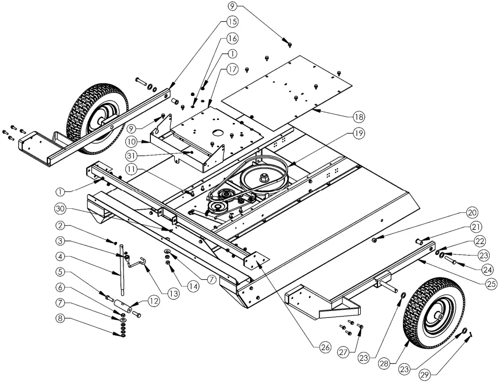
MOTOR BASE, WHEEL & HEIGHT ADJUSTMENT ASSEMBLIES
FIGURE 3
| Item # | Description | Part # |
| 1 | Nut – 5/16-18 Serrated Flange | NB170 |
| 2 | Nut, Push – 5/16 | NB117 |
| 3 | Knob Height Adjustment | H7K |
| 4 | Height Adjust Rod | 4006 |
| 5 | Bolt – 1/2-13 X 1 1/2 | 10046 |
| 6 | Nut – 1/2-13 Jam | NB118 |
| 7 | Washer – Bellville, .512×1.26x .138 | 10291 |
| 8 | 1/2 NR Mach Bushing 14 GA | NB177 |
| 9 | Screw – .312-18 x .75 | 26X249 |
| 10 | Guard – Battery Box Base | 21208* |
| 11 | Bolt – 5/16″ X 18 UNC X .75″ Flange Head | NB596 |
| 12 | Single Point Pivot Block | 4007* |
| 13 | Crank Rod | ES214 |
| 14 | Nut – 1/2-13 2-Way Jam Lock | NB121 |
| 15 | Weldment – Axle Bar, Right | 10356* |
| 16 | Washer – Nylon 1/4 | NB194 |
| Item # | Description | Part # |
| 17 | Motor Base | 10343* |
| 18 | Cover – Rear | 20941* |
| 19 | Belt – Blade, 50″ | 20655 |
| 20 | 1/2-13 Nyloc Nut | NB281 |
| 21 | Spacer | 10290 |
| 22 | Washer – 5/8 ID X 1 OD 14 GA | NB149 |
| 23 | Washer – 13/16 ID X 1 1/4 OD X 1/8 | NB195 |
| 24 | Bolt – 1/2-13 X 2 1/2 Hex Tap | NB588 |
| 25 | Weldment – Axle Bar, Left | 10355* |
| 26 | Tube – Front Weldment | 10342* |
| 27 | Bolt – 5/16-18 X 1 Serrated Flange | 10548 |
| 28 | Wheel/Tire – 4.8 X4-8 | 17383K |
| 29 | 1/8″ X 1″ Cotter Pin | NB126 |
| 30 | Bolt – Serrated Flange 1/4-20 | NB109 |
| 31 | Nut – 1/4-20 Kep | NB203 |
DECK ASSEMBLY
FIGURE 4
| Item # | Description | Part # |
| 1 | Deck – Weldment | 15727* |
| 2 | Screw – .312-18 x .75 | 26X249 |
| 3 | Side Gusset – Left | 15056* |
| 4 | Nut – 5/16-18 Serrated Flange | NB170 |
| 5 | Side Gusset – Right | 15057* |
| 6 | Z Bracket, Jack Support | 15055* |
| 7 | Front Rail/Deck Support | 15054* |
| 8 | Bracket – Remote Cable Detent | 15606* |
| 9 | Rail – RT44, Right | 17358* |
| 10 | Weldment – Blade Mount | 15005* |
| 11 | Rear Z Rail Brace – RT44 | 16371* |
| 12 | Rail – RT44, Left | 17357* |
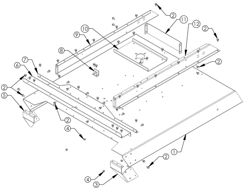
BLADE DRIVER ASSEMBLY
FIGURE 5
| Item # | Description | Part # |
| 1 | Nut – Nyloc 1″-8 | NB612 |
| 2 | Washer – 1″ X 2″ X 14GA | NB738 |
| 3 | Pulley – Blade, 10.3125″ | 4846 |
| 4 | Spacer – Pulley | 21344 |
| 5 | Bearing – Blade | 4845 |
| 6 | Shaft – Blade | 18844 |
| 7 | Nut – Nyloc 1/2″-13 | NB281 |
| 8 | Washer – USS Flat, 1/2″ | NB555 |
| 9 | Blade Driver Housing | 4858* |
| 10 | Bolt – 1/2″-13 X 2″ | NB509 |
| 11 | Cover – Dust (If Equipped) | 21372 |
| 12 | Washer – 1″ X 1 1/2″ X 10GA | NB614HT |
| 13 | Nut – Nyloc 3/4″-10 | NB609 |
| 14 | Weldment – Stump Jumper | 4859* |
| 15 | Blade | 10358 |
| 16 | Washer – 3/4″ X 1 1/4″ X 18GA | NB179 |
| 17 | Bolt – 3/4″-10 X 2″ | 11431 |
| 18 | Nut – Nyloc 1″-14 | 18850 |
| 19 | Kit – Replacement, Blade Driver | 18905 |
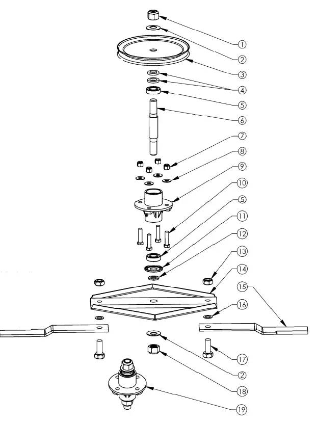
Note: The pulley, stump jumper, blades, blade hardware, and housing hardware are not included with the 18905 replacement blade driver kit.
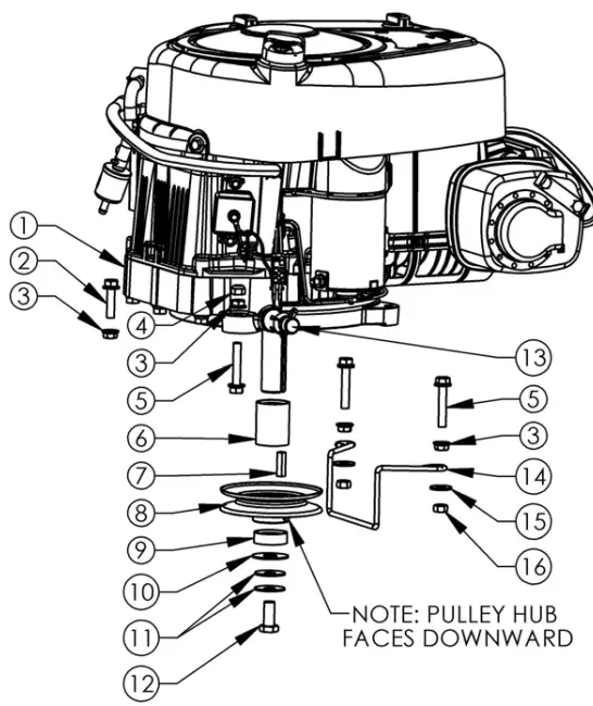
ENGINE PULLEY ASSEMBLY
FIGURE 6
| Item # | Description | Part # |
| 1 | Engine B&S | N/A |
| 2 | 5/16”-18 X 1 1/4” Serrated Flange Bolt | NB253 |
| 3 | 5/16-18 Serrated Flange Nut | NB170 |
| 4 | 5/16”-18 Nyloc Nut | NB181 |
| 5 | Bolt – Serr Flange, 5/16-18 X1 3/4 ZY Gr5 | NB515 |
| 6 | Spacer For Engine Pulley | BB105S |
| 7 | 1/4” X 1” Key Stock | 9031 |
| 8 | Engine Pulley- 4.25″OD,1 1/4” ID | BB105 |
| 9 | Spacer Lower For Engine Pulley | BB105SL |
| 10 | Washer | TR150W |
| 11 | Washer Belleville Engine Pulley | 699 |
| 12 | 7/16”-20 X 1 HCF GR5 ZP | NB452N |
| 13 | Oil Drain Valve | 16000 |
| 14 | RT44 Belt Guide | 4867 |
| 15 | 5/16” USS Flat Washer ZP | NB556 |
| 16 | Nut – Lock, 5/16-18 | NB558 |
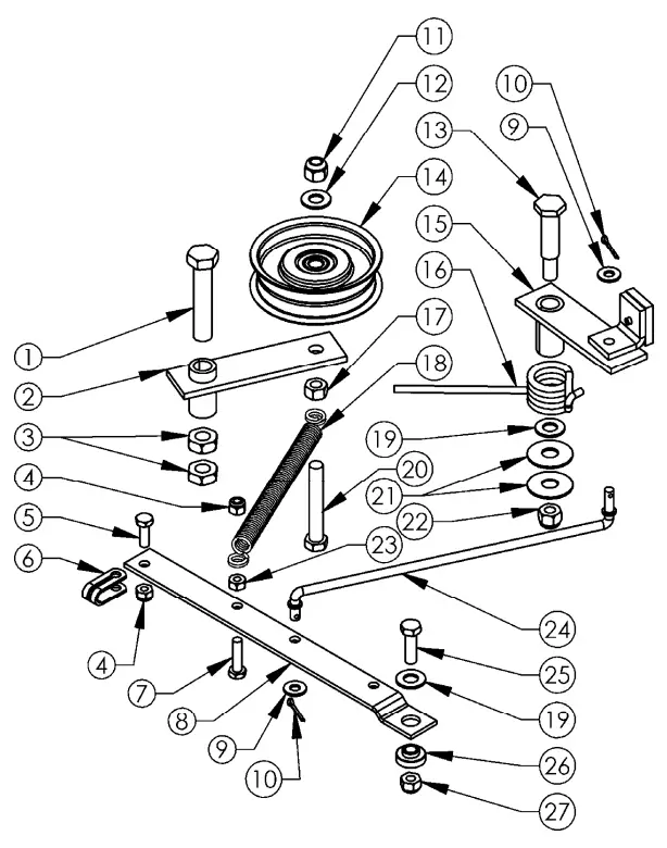
BELT ENGAGE CONFIGURATION
FIGURE 7
| Item # | Description | Part # |
| 1 | 1/2”-13 X 2 1/2” HCC GR5 ZP | NB510 |
| 2 | Idler Arm | 21285* |
| 3 | 1/2”-13 2-Way Jam Lock Nut | NB121 |
| 4 | 1/4”-20 Nylok Nut | NB180 |
| 5 | 1/4”-20 X 3/4” GR5 ZP | NB250 |
| 6 | Clutch Cable Clevis | 9023MOD |
| 7 | 1/4”-20 X 1” HCC GR5 ZP | NB102 |
| 8 | Belt Engage Arm | 4898* |
| 9 | 1/4” SAE Washer | NB274 |
| 10 | 5/64” X 3/4”Cotter Pin | NB519 |
| 11 | 3/8”-16 Nyloc Nut | NB182 |
| 12 | 3/8” SAE Washer | NB272 |
| 13 | 1/2” X 1-9/16” Shoulder Bolt | NB220 |
| 14 | Idler Pulley OD-3.25″, ID-3/8″ | B527 |
| 15 | Brake Arm Assembly | 4893 |
| 16 | Torsion Brake Spring | 9040 |
| 17 | 3/8”-16 HNC GR2 ZP | NB212 |
| 18 | Clutch Rod Spring | 682S |
| 19 | 3/8” Hardened Washer | NB196 |
| 20 | 3/8”-16 X 2 1/2” HTC GR5 ZP | NB619 |
| 21 | Washer Belleville | 699 |
| 22 | 3/8-16 Nyloc Nut | NB182 |
| 23 | 1/4”-20 HX Nut ZP | NB139 |
| 24 | Brake Rod | 4891* |
| 25 | 5/16”-18 X 1” HCC GR5 ZP | NB501 |
| 26 | Spacer | B99S |
| 27 | 5/16”-18 Nyloc Nut | NB181 |
CONSOLE ASSEMBLY
FIGURE 8
| Item # | Description | Part # |
| 1 | T Handle for Console | 4463* |
| 2 | 1/4-20 Nyloc Nut | NB180 |
| 3 | 5/16-18 Nyloc Nut | NB181 |
| 4 | 5/16-18 X 1 1/2 Bolt | NB505 |
| 5 | Console Weldment | 4575* |
| 6 | Key Switch Lock Washer | 9088 |
| 7 | Key Switch Nut | 9087 |
| 8 | Keys | KSK |
| 9 | Key Switch | 3623 |
| 10 | Console Mount Plate | 4852* |
| Item # | Description | Part # |
| 11 | 1/4 SAE Washer | NB274 |
| 12 | 1/4-20 X 2 1/2 HCC GR2 ZP | NB163 |
| 13 | 1/4-20 X 1 1/4 HCC GR5 ZP | NB560 |
| 14 | Link for Console | 4461* |
| 15 | 5/64 X 3/4 Cotter Pin | NB519 |
| 16 | Clutch Cable Clevis | 9023MOD |
| 17 | 1/4 X 1 1/2 Clevis Pin | NB518 |
| 18 | Engage Cable | 18817 |
| 19 | Wiring Harness, 12 Volt, 14.5HP Engine | 10299 |
| 20 | 1/4-20 Wing Nut ZP | NB608 |
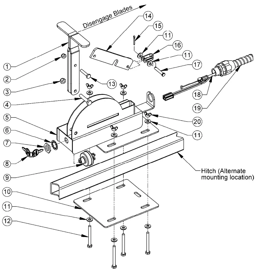
![]() When mounting the console assembly it may be necessary to mount it directly to the hitch tube depending on the vehicle you are towing it with. Some vehicle configurations will allow the console to be mounted to the vehicle (i.e. ATV rack). Place the console weldment (4575*) on top of the hitch tube and assemble the console mount plate (4852*) from underneath the hitch tube using the hardware provided. Make sure the wiring harness is secure and will not drag the ground. Periodically check to make sure all hardware is tight and the wiring harness is secure. NEVER operate this machine without the wiring harness being secure.
When mounting the console assembly it may be necessary to mount it directly to the hitch tube depending on the vehicle you are towing it with. Some vehicle configurations will allow the console to be mounted to the vehicle (i.e. ATV rack). Place the console weldment (4575*) on top of the hitch tube and assemble the console mount plate (4852*) from underneath the hitch tube using the hardware provided. Make sure the wiring harness is secure and will not drag the ground. Periodically check to make sure all hardware is tight and the wiring harness is secure. NEVER operate this machine without the wiring harness being secure.
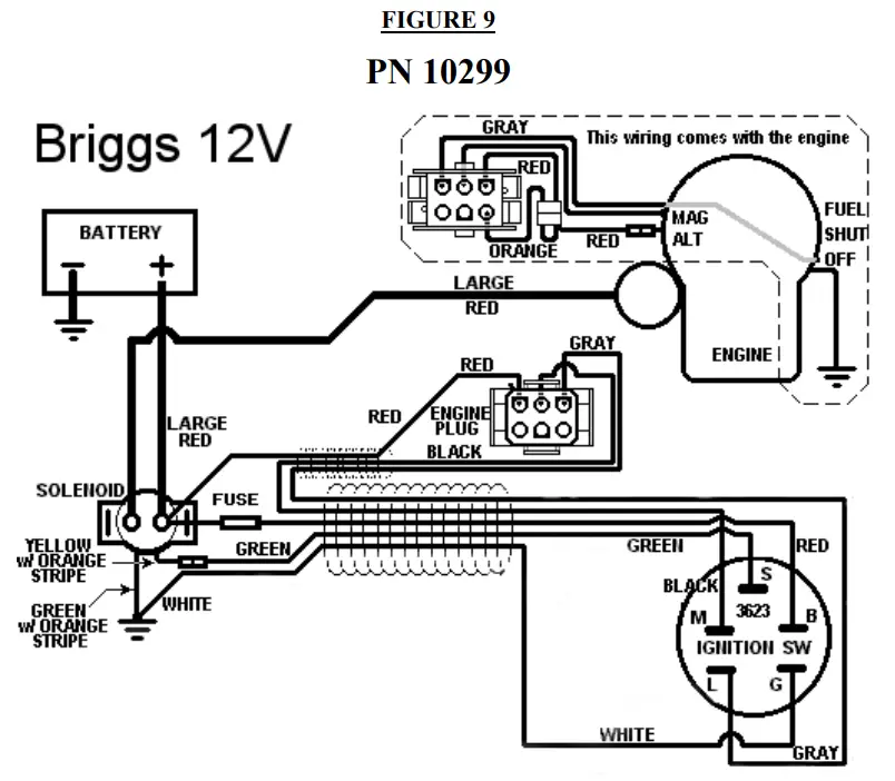
WIRING DIAGRAM, 14.5HP ENGINE
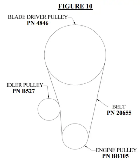
ENGINE TO BLADE PULLEY CONFIGURATION
REPAIR PARTS
Your 44’’ Trailcutter has been produced with components designed specifically for this machine. Although standard V-belts, springs, bearings, blades, pulleys, hardware, etc. look similar to parts used on other machinery, they may in some cases be made of different construction and/or materials.
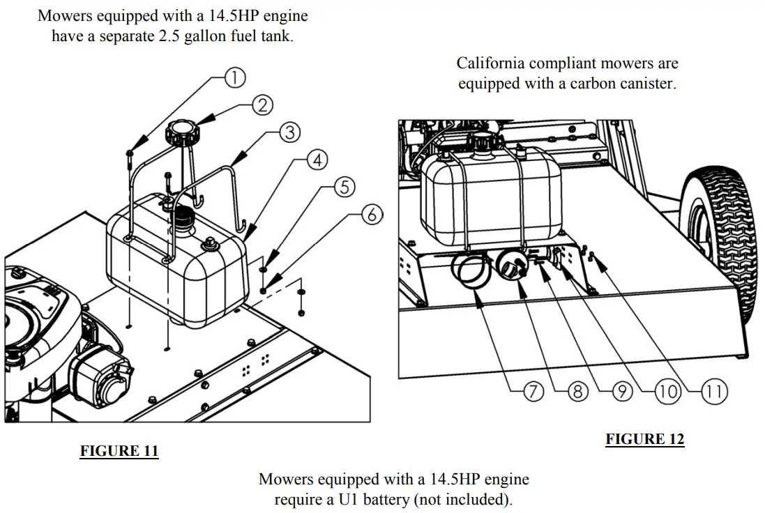
| Item # | Description | Part # |
| 1 | Bolt – Serr Flange 1/4-20 X 1 3/4 | 18236 |
| 2 | Cap – Fuel | 18221 |
| 3 | Bracket – Fuel Tank | 18225 |
| 4 | Fuel Tank – 2.5 Gallon | 18214 |
| 5 | Washer – SAE Flat 1/4 | NB274 |
| 6 | Nut – Nyloc 1/4-20 | NB180 |
| 7 | Cable Tie – Carbon Canister | 18219 |
| 8 | Carbon Canister – 2.50 Gallon | 18224 |
| 9 | Bolt – 10-24 X 3/4 | 024203 |
| 10 | Bracket – Carbon Canister | 17127 |
| 11 | Nut – 10-24 Nylon Lock | 024900 |
BATTERY HOLDER CONFIGURATION
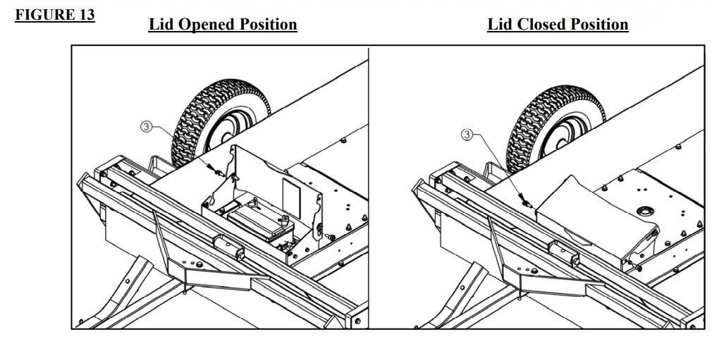
Note:
Use Thumbscrew [item #3] to hold the lid in the open position as shown in the illustration above.
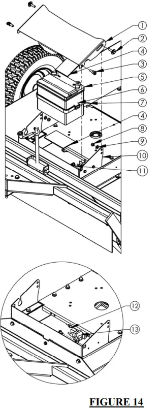
| Item # | Description | Part # |
| 1 | Guard – Battery Box Lid | 21209* |
| 2 | Bolt – Flange 5/16-18 | NB743 |
| 3 | Thumb Screw – 5/16-18 | 18802 |
| 4 | Rubber Pad | BATPAD |
| 5 | U1 Battery (not included) | N/A |
| 6 | Rubber Strap | AS013 |
| 7 | Strap Hook | AS049 |
| 8 | Nut – 5/16-18 Lock | NB181 |
| 9 | Washer – 5/16 Flat | NB275 |
| 10 | Guard – Battery Box Base | 21208* |
| 11 | Cage Nut – 5/16-18 | 21087 |
| 12 | Bolt – TCS 1/4-20 | NB114 |
| 13 | Solenoid Assembly 12 Volt | 1002004 |
| Not Shown | Battery Cable (Black 10″) | BCS |
| Not Shown | Battery Cable (10″ Red) | BCSR |
| Not Shown | Battery Cable Small Rubber Boot | BCBT |
SUGGESTED GUIDE FOR SIGHTING SLOPES FOR SAFE OPERATION

![]() WARNING: To avoid serious injury, operate your tractor up and down the face of slopes, never across the face. Do not mow slopes greater than 15 degrees. Make turns gradually to prevent tipping or loss of control. Exercise extreme caution when changing direction on slopes.
WARNING: To avoid serious injury, operate your tractor up and down the face of slopes, never across the face. Do not mow slopes greater than 15 degrees. Make turns gradually to prevent tipping or loss of control. Exercise extreme caution when changing direction on slopes.
- Fold this page along the dotted line indicated above.
- Hold the page before you so that its left edge is vertically parallel to a tree trunk or other upright structure.
- Sight across the fold in the direction of the hill slope you want to measure.
- Compare the angle of the fold with the slope of the hill.
181096 10.23.01 Printed in U.S.A.
NOTES
44” COUNTRY CUT
TRAIL CUTTER
Each mower has its own model number. Each engine has its own model number. The model number for the mower will be found on the right-hand side of the motor mount. The model number for the engine will be found on the top of the valve cover.
All mower parts listed herein may be ordered directly from Swisher or your nearest Swisher dealer. All engine parts may be ordered from the nearest dealer of the engine supplied with your mower.
WHEN ORDERING PARTS, PLEASE HAVE THE
FOLLOWING INFORMATION AVAILABLE:
* PRODUCT – RC44’’ COUNTRY CUT TRAIL CUTTER
* SERIAL NUMBER – _______________
* MODEL NUMBER – _______________
* ENGINE MODEL NUMBER – _______________
TYPE – _______________
* PART NUMBER
* PART DESCRIPTION
TELEPHONE – 1-800-222-8183
FAX – 1-660-747-8650
SWISHER ACQUISITION INC.
1602 CORPORATE DRIVE
WARRENSBURG, MO 64093
www.swisherinc.com.
![]() CHANGING YOUR LANDSCAPE SINCE 1945
CHANGING YOUR LANDSCAPE SINCE 1945
When ordering replacement parts
* = USE PAINT CODE: TK=BLACK
SWISHER ACQUISITION INC.
1602 CORPORATE DRIVE, WARRENSBURG, MISSOURI 64093
PHONE (660) 747-8183 FAX (660) 747-8650
USA
8/23/2019 of US and Global Part
17338 REV 18-236


