![]()
Quick Start Guide
UCX-2×1-HC30, UCX-2×2-H30, UCX-4×2-HC30, UCX-4×2-HC30D
Important Safety Instructions
Please read the supplied safety instruction document before using the product and keep it available for future reference.
Introduction
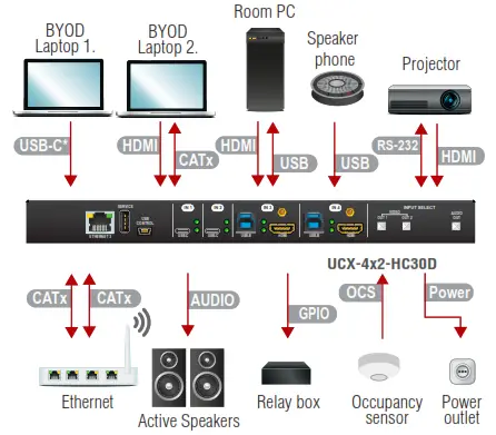
Lightware’s universal switcher enhances and extends the possibilities of a meeting room and allows meeting participants to easily use their own devices such as laptops, and preferred video conference platforms while also utilizing the available assets of the meeting space, just like the HDMI displays, room cameras, and other USB peripherals.
The device utilizes the USB-C connectivity for a simplified transmission of 4K video, audio, control signals and power, and allows data speeds of up to 5 Gbps under the USB 3.1 Gen1 and allowing video resolution capabilities up to 4K@60Hz at 4:4:4.

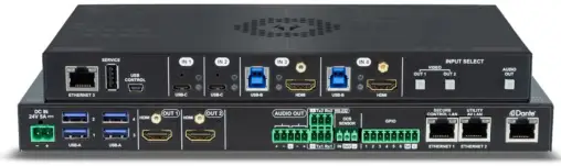
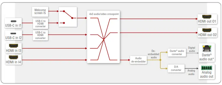
The UCX-4×2-HC30D model also thrives when it comes to audio capabilities, offering analog audio
de-embedding feature as well as support for DANTE/AES67 network connection to send DANTE/AES67 audio stream directly to a dedicated audio system.

Box Contents
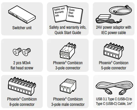
* USB Type-C cable is not supplied with the UCX-2×2-H30 model.
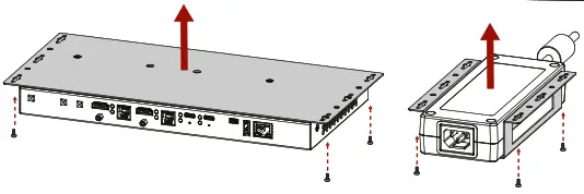
Mounting the Device (with optionally available accessories)
The examples demonstrate the applications of UD Kit accessories:
| Insert the power supply into UD Mounting PSU F100.
| Fix the UD Mounting plate F100 to the switcher by fastening the screws (these 2pcs screws are supplied with the switcher).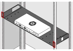 |
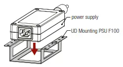
![]() UD-Mounting plate F100 and UD Mounting PSU F100 do not contain the fixing
UD-Mounting plate F100 and UD Mounting PSU F100 do not contain the fixing
AV Port Diagram (UCX-4×2-HC30D) screws, they can be purchased from the local hardware store. 2x4pcs M3-M5 metric or Audio Cable Wiring Guide wood screws needed, M3 size is recommended.![]() To ensure the correct ventilation and avoid overheating, insert the switcher face down to the UD KIT to keep the ventilation holes free.
To ensure the correct ventilation and avoid overheating, insert the switcher face down to the UD KIT to keep the ventilation holes free.
Mounting the Device with UD Kit Rack Shelf (with optionally available accessories)
The example on the right demonstrates the applications of UD Kit Rack Shelf accessories.
![]() ¢ For fixing the device to a Rack shelf, use the screw supplied with the switcher. Longer screw may touch internal parts and harm the device.
¢ For fixing the device to a Rack shelf, use the screw supplied with the switcher. Longer screw may touch internal parts and harm the device.
Factory Default Settings
To restore factory default values, do the following steps: Make sure the switcher is powered
off. Press and keep pressing the VIDEO OUT2 (VIDEO IN2 button in UCX-2×1-HC30 model)
button. Power on the switcher while the VIDEO OUT2* button is being pressed for 10 seconds.
The device restores the factory default settings and reboots.
| IP address | Dynamic (DHCP is enabled) |
| Hostname | lightware-cserialno> |
| Video Crosspoint setting | 11 on 01, 13 on 02 |
| HDCP mode (in) – UCX-4×2-HC30(D) | IL 12: HDCP 1.4;13,14: HDCP 2.2 |
| HDCP mode (in) UCX-2×1-HC30, UCX-2×2-H30 | 11,12: HDCP 2.2 |
| HDCP mode (out) | Auto |
| Signal type | Auto |
| Emulated EDID | F47- (Universal HDMI with PCM audio) |
| Audio Crosspoint setting | 11 on 03 (UCX-2×1-HC30: 11 on 02) |
| Analog audio output levels | Volume (dB): 0.00; Balance: 0 (center) |
| Video Autoselect | Follow video 01 |
| USB-C Power Limit (UCX-2×1-HC30) | 60W output power |
| USB-C Power Limit (other models) | Equal output power |
| DP Altemate Mode Policy | Auto |
| Port Power Role | Dual Role |
| USB Autoselect | Follow video 01 |
| Dl-D4 Power 5V Mode | Auto |
| RS-232 port setting | 9600 BAUD, 8, N, 1 |
| RS-232 serial over IP | Enabled |
| HTTP, HTTPS | Enabled |
| HTTP, HTTPS authentication | Disabled |
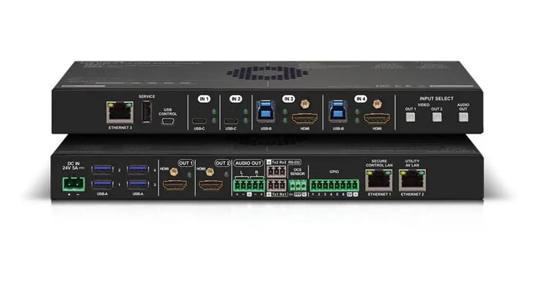
Front View (UCX-4×2-HC30D)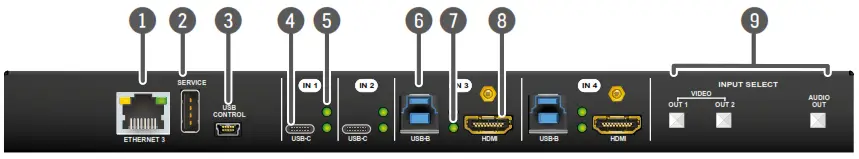
| 1 Configurable Ethernet Port | RJ45 connector for configurable 100Base-T Ethernet communication. |
| 2 USB-A Port | The service function will be added by a future firmware updates. |
| 3 USB mini-B Port | The LW3 control function will be added by the future firmware upgrade. |
| 4 USB-C Port | Displayport 1.2 and USB 3.1 Gen1 connections, AV signal can be transferred up to a resolution of 4K@60Hz 4:4:4 and data speeds up to 5 Gbps with remote charging. Use cables certified for USB 3.1 Gen1 (5Gbps) and Displayport Alternate mode HBR2 (4×5.4Gbps) applications. |
| 5 Video Input Status LEDs | See the details in the table on the right. |
| 6 USB-B Port | Upstream ports for connecting USB host devices (e.g. computer). |
| 7 USB Status LEDs | See the details in the table on the right. |
| 8 HDMI Input Ports | HDMI input ports for sources. The applied cable shall not be longer than 5m (22AWG) when signal resolution is 4K. Use cables certified for HDMI 2.0 (3x6Gbps) applications. |
| 9 Input Select Button | For more details about the button functionality, see the table on the right. When LEDs blink green three times after pressing the button, they show that the front panel lock is enabled. |
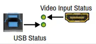
Arrangement of the Status LEDs![]()
Rear View (UCX-4×2-HC30D)
| 1 DC Input | The device can be powered by an external 120W power supply. Connect the output to the 2-pole Phoenix®connector. For more details, see powering options below. |
| 2 USB-A Port | Downstream ports for connecting USB peripherals (e.g. camera, keyboard, multitouch display) with USB 3.1Gen1 data speed. |
| 3 HDMI Output Ports | HDMI output ports for connecting to the sink devices. |
| 4 Video Output Status LED | See the details in the table on the right. |
| 5 Analog audio port | Audio output port (5-pole Phoenix) for the balanced analog audio output signal. The signal is de-embedded from the selected video signal. |
| 6 RS-232 port | 3-pole Phoenix connector for bi-directional RS-232 communication. |
| 7 OCS sensor | 3-pole Phoenix ® connector (male) for connecting an occupancy sensor. The port provides a 24V output voltage (50mA). |
| 8 GPIO | 8-pole Phoenix ® connector for configurable general purpose. Max. input/output voltage is 5V, see the details on the next page. |
| 9 Secure Control LAN | RJ45 connector for secure 100Base-T Ethernet communication. |
| q Utility AV LAN | RJ45 connector provides room utility Ethernet connection for e.g BYOD laptops. |
| w Dante ® Audio Output | In the UCX-4×2-HC30D model: the RJ45 connector for de-embedding the HDMI audio can be transmitted as a 2-channel Dante ® or AES67 source. |
UCX-2×2-H30 model has no Utility AV LAN port.
![]() Always use the supplied power supply. Warranty void if damage occurs due to use a different power source.
Always use the supplied power supply. Warranty void if damage occurs due to use a different power source.
Powering Options
UCX series switchers are designed to provide power delivery for the connected device over the USC-C connectors. The following operation modes are available:
- Charge one device on the chosen port with up to 60W. The other port can supply up to 5V/3A.
- Charge one device with 30W (in this case, the other USB-C port can supply 30W or 5V/3A)
Power profiles can be set with Lightware Device Controller Software, REST API or with LW3
protocol commands.
Software Control – Using Lightware Device Controller (LDC)
The device can be controlled from a computer using the Lightware Device Controller software. The application is available at www.lightware.com, install it on a Windows PC or a macOS and connect to the device via LAN.

Firmware Upgrade
Lightware Device Updater2 (LDU2) is an easy and comfortable way to keep your device up-to-date. Establish the connection via Ethernet. Download and install LDU2 software from the company’s website www.lightware.com where you can find the latest firmware package as well.

UCX-2×1-HC30
Use IN1 and IN2 buttons for selecting the video source. IN1 button switches the USB-C IN1 to the output, IN2 button switches the HDMI IN2 to the output.
Connecting Steps
♦Connecting USB-B and HDMI ports to the same PC or laptop is recommended in case of
I3 and I4 inputs. sensor outlet Active Speakers
AV Port Diagram (UCX-4×2-HC30D)
USB Port Diagram (UCX-4×2-HC30D)
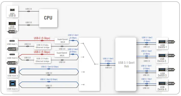
♦For more details about the power delivery of the USB-C port see Powering Options section.
Front Panel LEDs
Video-Input Status LED (the upper one) | ||
 | on | There is a valid video signal on this port. |
 | off | There is no valid video signal on this port. |
 | blink at once | The port is selected by a button press. |
USB Status LED (the below one) | ||
 | on | The USB Host is connected and selected. |
 | off | No USB Host or deselected port. |
Rear Panel LEDs
Video Output Status | ||
| on | The video signal is present. | |
| off | The signal is not present or muted. | |
When Dark Mode is enabled, no LEDs are lit, even though the device is fully functional.
Dante ® Audio Out (in UCX-4×2-HC30D model)
| LED state | Left LED | Right LED | Function |
 | Off | Off | No power |
 | green | Solid red | Dante is booting |
 | Blinking green | Solid green | Slave with sync (normal operation) |
 | Blinking green | Blinking green | Clock master (normal operation) |
 | Blinking green | Blinking red | Acquiring clock sync (normal operation) |
 | Alternating red/green | Alternating red/green | Identity (blinking for 6 seconds) |
 | Blinking red | Blinking red | Dante fail safe |
 | Blinking orange | Blinking orange | Dante is upgrading |
Setting a Dynamic IP Address (DHCP)
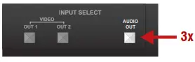
1. Keep the Audio out button pressed for 5 seconds; all front panel LEDs start to blink. 2. Release the button, then press it 3 times quickly. DHCP is now enabled.
Lock / Unlock Buttons
Press the VIDEO OUT1 (VIDEO IN1 in UCX-2×1-HC30 model) and AUDIO OUT buttons together (within 100 ms) to disable/enable front panel buttons; front panel LEDs blink 4 times when locking/ unlocking.
OCS (Occupancy) Sensor
The switcher is supplied 3-pole Phoenix ® connector (male) which is for connecting an OCS sensor.
Plug pin assignment: 1: Configurable; 2: 24V (max. 50 mA); 3: Ground

| The signal levels for the Pin 1 | Input voltage (V) | Max. current (mA) |
| Logic low level | 0 – 0.8 | 30 |
| Logic high level | 2 -5 | 18 |
![]() Occupancy sensor connector and GPIO port are not compatible with each other because of the voltage level difference, please do not connect them directly.
Occupancy sensor connector and GPIO port are not compatible with each other because of the voltage level difference, please do not connect them directly.
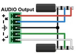
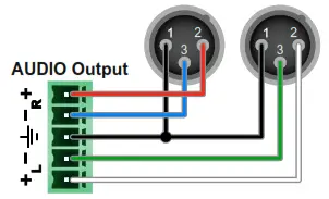
Audio Cable Wiring Guide
wood screws needed, M3 size is recommended. The Taurus UCX series is built with 5-pole Phoenix output connectors. See below a few examples of the most common assembling cases.
| Balanced output to balanced input Phoenix – 2×6.3 (1/4”) TRS | Balanced output to balanced input Phoenix cable – 2x XLR plugs |
 |  |
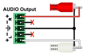
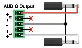
| Balanced output to an unbalanced input Phoenix – 2x RCA | Balanced output to an unbalanced input Phoenix – 2x 6.3 (1/4”) TS |
 |  |
GPIO (General Purpose Input/Output Ports)
The device has seven GPIO pins that operate at TTL digital signal levels and can be set to a high or low levels (Push-Pull). The direction of the pins can be input or output (adjustable). The signal levels are the following:
| Input voltage (V) | Output voltage (V) | Max. current (mA) | |
| Logic low level | 0 – 0.8 | 0 – 0.5 | 30 |
| Logic high level | 2 -5 | 4.5 – 5 | 18 |
Plug pin assignment 1-6: Configurable, 7: 5V (max. 500 mA); 8: Ground The recommended cable for the connectors is the AWG24 (0.2 mm 2 diameters) or the generally used ‘alarm cable’ with 4×0.22 mm 2 wires.
The maximum total current for the six GPIO pins is 180 mm, the max. supported input/ output voltage is 5V.
RS-232
The switcher provides a 3-pole Phoenix connector for bi-directional serial communication. The signal levels are the followings:
| Output voltage (V) | |
| Logic low level | 3 – 15 |
| Logic high level | -15 – 3 |
Plug pin assignment: 1: Ground, 2: TX data, 3: RX data
Further Information
The document is valid with the following firmware version: 1.2.0
The User’s manual of this appliance is available on www.lightware.com.
See the Downloads section on the dedicated product page.
Contact Us
[email protected]
+36 1 255 3800
[email protected]
+36 1 255 3810
Lightware Visual Engineering LLC.
Peterdy 15, Budapest H-1071, Hungary
Doc. ver.: 1.3
19200183


