![]()
HEAT CONVECTOR
INSTALLATION AND OPERATION INSTRUCTIONS
MODEL HC-20

IMPORTANT
READ AND UNDERSTAND INSTRUCTIONS BEFORE INSTALLING OR USING THE UNIT.
RETAIN INSTRUCTIONS FOR FUTURE REFERENCE. CHECK LOCAL CODES AND ORDINANCES FOR PERMITTED USE.
SECTION A:
SPECIFICATIONS
| Model: | HC-20 |
| Type: | Hot Water Heating, Floor Standing Type |
| Heat Rating Range: | 3,000 to 20,000 BTU/h (0.88 to 5.9 kW) *See the chart below for details. |
| Max. Allowable Pressure: | 142 PSI (0.98 MPa) |
| Heat Exchanger Capacity: | 0.16 gal. (0.6 L) |
| Flow Rate Range: | 0.5 gal./min. to 1.5 gal./min. (1.89 to 5.68 L/min.) |
| Hot Water Temperature: | 110˚F – 190˚F (43˚C – 87.8˚C) |
| Noise Level | High: 39 dBA Med: 28 dBA Low: 19 dBA NOTE: Noise levels tested at 2.5 m. |
| Air Volume | High: 226, CFM Med: 141, CFM Low: 64 CFM |
| Operation Mode: | Auto Fan Mode – 4 fan speeds (High/Med/Low/Off) Manual Fan Mode – 3 fan speeds (High/Med/Low) |
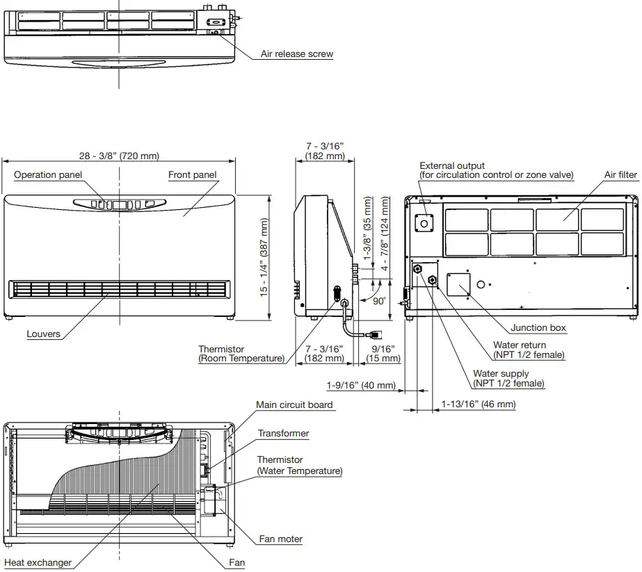
| Dimensions (W x H x D): | 28-3/8” x 15-1/4” x 7-3/16” (720 x 387 x 182 mm) |
| Weight: | 27.5 lbs. (12.5 kg) |
| Set Temperature Range: | 50˚F – 90˚F (12˚C – 30˚C) |
| Electrical Rating: | 120 Volts AC, Single phase 60 Hz High – 37W (0.4A) Med – 16W Low – 9W |
| Electrical Current Fuse: | 5A |
Heating Performance: (BTU)
Circulation Water Volume | Fan Speed | The temperature of Circulation Water | |||||||
| GPM (L/min) | 110˚F (43˚C) | 120˚F (49˚C) | 130˚F (54˚C) | 140˚F (60˚C) | 150˚F (66˚C) | 160˚F (71˚C) | 170˚F (77˚C) | 180˚F (82˚C) | |
| 0.5 GPM (1.89 L/min) | Low | 2939 BTU | 3646 BTU | 4353 BTU | 5059 BTU | 5766 BTU | 6473 BTU | 7179 BTU | 7886 BTU |
| Medium | 5081 BTU | 6099 BTU | 7116 BTU | 8133 BTU | 9151 BTU | 10168 BTU | 11185 BTU | 12203 BTU | |
| High | 6002 BTU | 7368 BTU | 8733 BTU | 10099 BTU | 11464 BTU | 12830 BTU | 14195 BTU | 15561 BTU | |
| 1 GPM (3.79 L/min) | Low | 3429 BTU | 4105 BTU | 4780 BTU | 5456 BTU | 6132 BTU | 6808 BTU | 7484 BTU | 8160 BTU |
| Medium | 5932 BTU | 7096 BTU | 8260 BTU | 9424 BTU | 10588 BTU | 11752 BTU | 12916 BTU | 14080 BTU | |
| High | 7561 BTU | 9155 BTU | 10749 BTU | 12344 BTU | 13938 BTU | 15532 BTU | 17126 BTU | 18720 BTU | |
| 1.5 GPM (5.68 L/min) | Low | 3866 BTU | 4532 BTU | 5198 BTU | 5863 BTU | 6529 BTU | 7195 BTU | 7860 BTU | 8526 BTU |
| Medium | 6485 BTU | 7956 BTU | 9427 BTU | 10899 BTU | 12370 BTU | 13841 BTU | 15313 BTU | 16784 BTU | |
| High | 8305 BTU | 9998 BTU | 11691 BTU | 13385 BTU | 15078 BTU | 16771 BTU | 18464 BTU | 20158 BTU | |
Room Temperature: 68˚F (20˚C) (kW)
| Circulation Water Volume | Fan Speed | The temperature of Circulation Water | |||||||
| GPM (L/min) | 110˚F (43˚C) | 120˚F (49˚C) | 130˚F (54˚C) | 140˚F (60˚C) | 150˚F (66˚C) | 160˚F (71˚C) | 170˚F (77˚C) | 180˚F (82˚C) | |
| 0.5 GPM (1.89 L/min) | Low | 0.87 kW | 1.08 kW | 1.28 kW | 1.49 kW | 1.70 kW | 1.91 kW | 2.11 kW | 2.32 kW |
| Medium | 1.50 kW | 1.80 kW | 2.10 kW | 2.40 kW | 2.70 kW | 2.99 kW | 3.29 kW | 3.59 kW | |
| High | 1.77 kW | 2.17 kW | 2.57 kW | 2.97 kW | 3.37 kW | 3.77 kW | 4.17 kW | 4.57 kW | |
| 1 GPM (3.79 L/min) | Low | 1.01 kW | 1.21 kW | 1.41 kW | 1.61 kW | 1.81 kW | 2.00 kW | 2.20 kW | 2.40 kW |
| Medium | 1.75 kW | 2.09 kW | 2.43 kW | 2.78 kW | 3.12 kW | 3.46 kW | 3.80 kW | 4.14 kW | |
| High | 2.23 kW | 2.70 kW | 3.16 kW | 3.63 kW | 4.10 kW | 4.57 kW | 5.03 kW | 5.50 kW | |
| 1.5 GPM (5.68 L/min) | Low | 1.14 kW | 1.34 kW | 1.53 kW | 1.73 kW | 1.92 kW | 2.12 kW | 2.31 kW | 2.51 kW |
| Medium | 1.91 kW | 2.35 kW | 2.78 kW | 3.21 kW | 3.64 kW | 4.07 kW | 4.50 kW | 4.93 kW | |
| High | 2.45 kW | 2.94 kW | 3.44 kW | 3.94 kW | 4.43 kW | 4.93 kW | 5.42 kW | 5.92 kW | |
Room Temperature: 68˚F (20˚C)
Hydraulic Resistance
| Circulation Water Volume | Resistance |
| 1.5 G (5.68 L/min) | 7.0 PSI/48 kPa |
| 1.0 G (3.79 L/min) | 3.2 PSI/22 kPa |
| 0.5 G (1.89 L/min) | 0.9 PSI/6 kPa |
SECTION B:
UNPACKING
UNPACKING
- Unpack the unit carefully.
- Check to see if there are any loose screws that may have occurred in transit.
- Take accessories and the instruction manual out of the carton.
ACCESSORY PARTS
- Installation and Operation Instructions
- Warranty Card
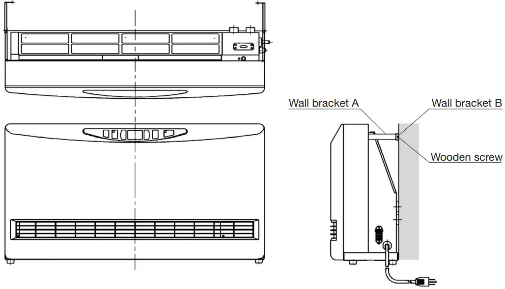
- Wall Fixing Kit (Wall bracket – 2 sets, Screw – 2 pcs., Wooden screw – 2 pcs.)
DIMENSIONAL OUTLINE
SECTION C:
SAFETY TIPS FOR INSTALLATION
The instructions which are contained in this manual are classified into the following two types, which are “WARNING” and “CAUTION”. These instructions are intended to provide important information for safe operation.
“WARNING” indicates the possibility of causing the user a fatal accident or serious injury if the unit is incorrectly operated.
“CAUTION” indicates the possibility of causing the user injuries or material damages if the unit is incorrectly operated.
![]() WARNING
WARNING
- Improper installation, adjustment, modification, or service and maintenance by an unauthorized person may cause SERIOUS UNIT DAMAGE, BODILY INJURY, HAZARD, OR PROPERTY DAMAGE. This unit should be installed by a licensed, authorized person(s) due to the necessity of making electrical and water connections. Refer to the installation and operation instructions for assistance, or consult your dealer for further information.
- HAZARD OF ELECTRICAL SHOCK! Before removing any access panels of the unit for service, make sure the electrical supply to the unit is shut off. Failure to do this may result in HAZARD, SERIOUS BODILY INJURY, OR PROPERTY DAMAGE.
- Check and comply with all state, and local codes before beginning the installation.
![]() CAUTION
CAUTION
- Keep the area around the unit clean and free of flammable materials.
- RISK OF FIRE AND ELECTRIC SHOCK. DO NOT apply any excessive force or pressure to the power supply cord. Make sure the plug is free of dust. Be sure the plug fits the receptacle securely.
SECTION D:
INSTALLATION
WARNING: This unit must be installed in accordance with these instructions, local codes, ordinances, and/or in the absence of local codes National Plumbing standards.
Check and comply with all state and local codes before beginning the installation.
This unit should be installed by a licensed, authorized person(s) due to the necessity of making electrical and water connections.
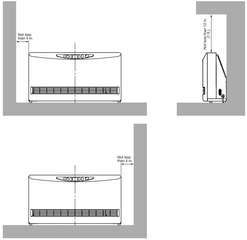
SELECTING A LOCATION
Select a place to install the unit where hot water and electric supply are easily available.
- Select a place that is free of combustible substances.
- Select a place where proper maintenance and repair can be provided for the unit after installation.
- Install the unit on the level floor.
NOTE: The unit may be installed on the wall directly.
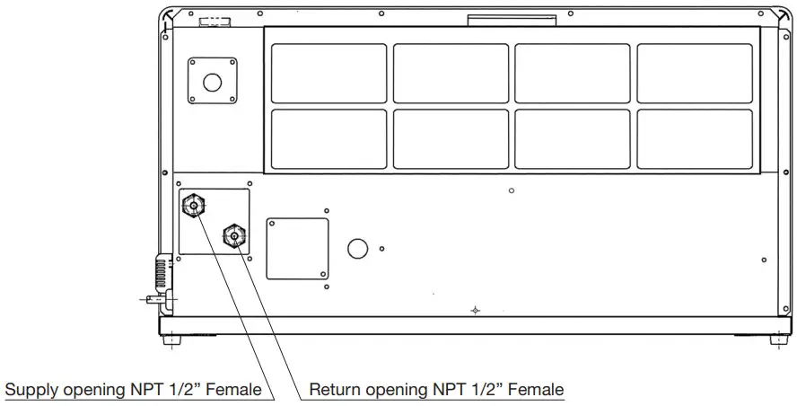
PLUMBING
NOTE: Make sure the piping for the unit is laid out properly, and also check for any water leakage.
- Install heat insulation material on the water piping to prevent heat loss.
- Copper or polyethylene pipes should be used for connecting pipes.
- It is recommended to install shut-off valves on the supply and return sides for easy removal.
- It is recommended to install a bypass loop in the water pipes with a shut-off valve.
- Be sure to use anti-freezing solution, or non-scale block, or non-slime block, or corrosion-free water for the circulation water.
The temperature of circulation water has to be less than 190˚F (87.8˚C)
Maximum allowable working pressure has to be less than 142 PSI
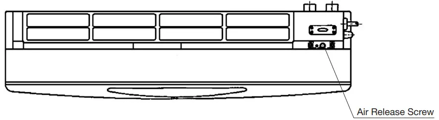
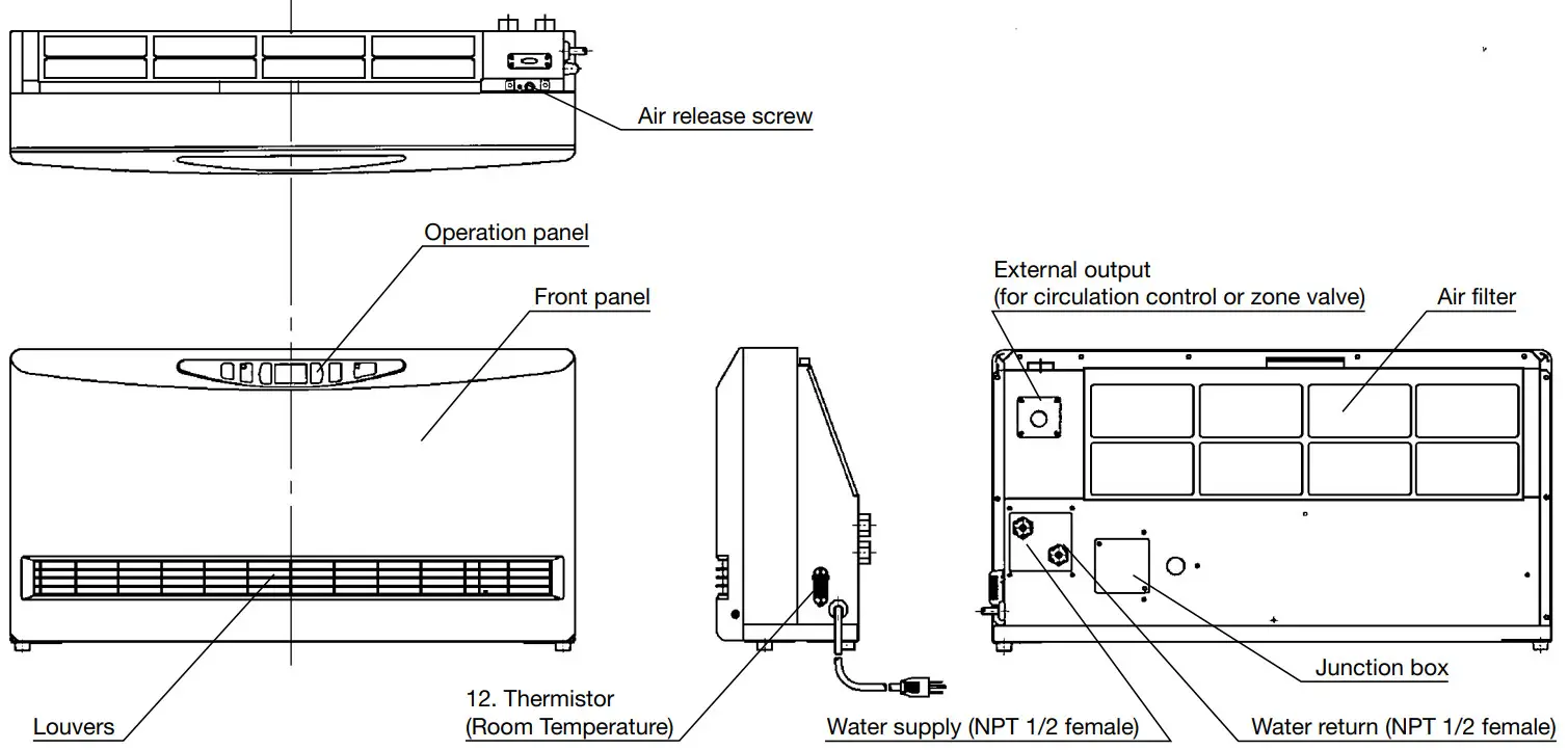
REMOVING TRAPPED AIR
When operating for the first time, air may be trapped in the system. To release the air out of the piping and the unit, follow the procedures below.
- To remove the air release cover, remove the two (2) screws.
- Loosen the Air release screw by using the flat head screwdriver. Release the air out of the piping.
- Tighten the air release screw after removing all trapped air.
- Immediately wipe off any spilled water.
- Attach the Air release cover.
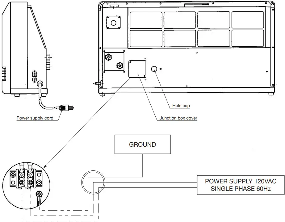
PERMANENT WIRING INSTALLATION
POWER SOURCE: 120V AC, 60Hz single phase
- Turn off the main circuit breaker. Disconnect the power supply cord from the power source.
- Remove the two (2) screws and Junction box cover on the backside of the unit.
- Disconnect the ground wire (green) from the power supply cord bracket.
- Disconnect the two power supply wires from the Junction box terminal.
- Squeeze the strain relief bushing with adjustable pliers to remove the plastic bushing from the unit (right side).
Remove the power supply cord. - Remove the Hole cap on the backside of the unit and put it in the hole on the right side where the power supply cord was installed.
- Use at least AWG 14/2 gauge copper wire to the Junction box, feed wire through the hole to the right of the Junction box Cover, and use a 1/2 inch clamp connector to secure to Heat convector cabinet.
- Affix the Junction box cover to the unit and insert screws.
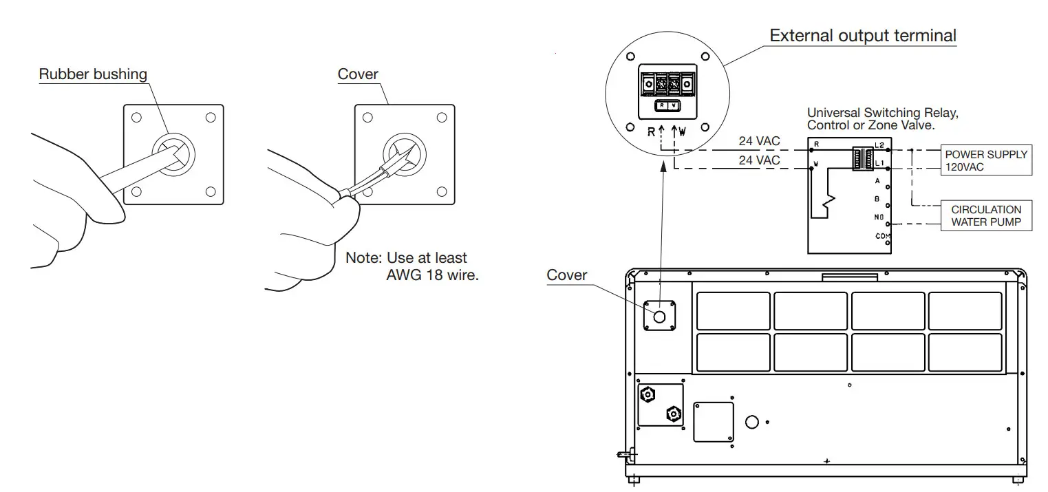
EXTERNAL OUTPUT TERMINAL WIRING
This unit has an External output terminal for low-voltage (24 volts or less) contacts to connect to a circulation pump control or zone valve. When connecting the circulation control or zone valve unit to this terminal, it is possible to stop the circulation by the output from the internal contact switch in the Heat convector. When the Power switch is
ON and there is a call for heat, the internal contact switch is closed. When the power switch is OFF or the Room temperature reaches 4 degrees above the Set temperature the internal contact switch is open.
WIRING FOR EXTERNAL OUTPUT
- Remove the four (4) screws and the cover on the backside of the unit.
- Cut the rubber bushing of the cover with a cutter and insert the wire for the circulation control or zone valve.
- Connect the wire to the terminal block in accordance with the color indication.
- Fix the cover to the unit with the four (4) screws.
[EXTERNAL OUTPUT SPECIFICATIONS]
| Contact Rating | 3A 24VAC |
| Maximum Switching Voltage | 30VDC |
| Maximum Carrying Current | 5A |
| Maximum Switching Power | 90W |
| Minimum Switching load | 10mA 5VDC |
After installation is completed, secure the unit to the wall with the wall fixing kit provided with the unit.
NOTE: Make sure the unit is parallel to the wall.
SECTION E:
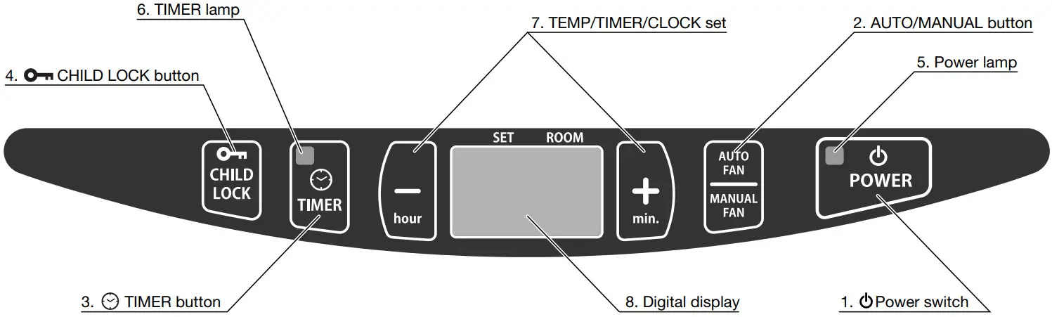
OPERATING CONTROLS AND PART NAMES
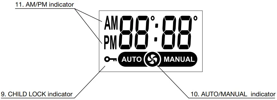
DIGITAL DISPLAY
| 1. | The main switch turns the unit on or off. |
| 2. AUTO/MANUAL button: | Button switches fan speed to either AUTO and MANUAL. |
| 3. TIMER button: | The button turns Timer operation mode on or off. |
| 4. | The button turns CHILD LOCK operation mode on or off. |
| 5. POWER lamp: | Light means the unit is in operation. |
| 6. TIMER indicator: | Light means the unit operating in Timer setting mode. |
| 7. TEMP/TIMER/CLOCK set: | TEMP/TIMER/CLOCK set modes can be set by pressing “–/hour” or “+/min.” buttons. |
| 8. Digital display: | Displays clock, set temperature, room temperature, and error code. |
| 9. CHILD LOCK indicator: | Light – The unit is in CHILD LOCK mode. |
| 10. AUTO/MANUAL indicator: | Light – Digital display shows fan speed mode. |
| 11. AM/PM indicator: | Light – Digital display shows the current time. |
| 12. Thermistor: (Room Temperature Sensor) | Constantly senses room temperature and supplies information to the unit so that desired room temperature can be maintained. |
| Power supply cord: | For use in 120V, AC electrical outlet. |
SECTION F:
SAFETY TIPS FOR OPERATION
The instructions which are contained in this manual are classified into the following two types, which are “WARNING” and “CAUTION”. These instructions are intended to provide important information for safe operation.
“WARNING” indicates the possibility of causing the user a fatal accident or serious injury if the unit is incorrectly operated.
“CAUTION” indicates the possibility of causing the user injury or material damages if the unit is incorrectly operated.
![]() WARNING
WARNING
- ALWAYS plug into 120 V, 60 Hz, single-phase electrical outlet.
- Due to high surface temperatures, keep the heater away from children, furniture, and clothing while in operation.
- DO NOT touch the Heat exchanger.
- NEVER insert objects of any kind into the air intake or air outlet.
- DO NOT unplug if your hands are wet. An electrical shock may occur.
- DO NOT run power cord under carpets, rugs, or floor mats of any kind.
- DO NOT apply any excessive force or pressure to the power supply cord.
- Make sure that the plug is free of dust or debris.
- DO NOT use an extension cord.
- RISK OF INJURY FROM MOVING PARTS AND ELECTRICAL SHOCK. Disconnect the power cord before servicing the unit.
![]() CAUTION
CAUTION
- Keep objects more than 20 in. (50 cm) away from the front of the unit.
- DO NOT place animals, plants, or combustion equipment in a place that is subjected to the direct airflow of the unit.
- DO NOT ride or place objects on the unit.
- DO NOT try to repair or alter the unit by yourself.
- DO NOT place flower vases or water containers on the top of the unit.
- DO NOT block the air inlet or outlet.
- To prevent abnormal operation and prolong heater life, be sure to perform routine maintenance.
SECTION G:
BEFORE USE
- Position of the Unit
Make sure the position of the unit is level.
- Plugin the Unit
Plug unit into a 120V AC electrical outlet. On digital display will appear two sets of
dashes. Indicating the time is not set. - Setting the Clock
Important: The clock on the unit must always be set to the current time. Press the “–/hour” and “+/min.” buttons to change to the correct time. NOTE: “–/hour” or “+/min.” button will change the time everyone (1) unit.
Holding the button continuously will cause the time to change rapidly.
NOTE: In the event of a power failure all clock and timer settings are canceled and will need to be reset.

OPERATION
NOTE: When you first use your unit, or when you plug the unit into an electrical outlet to start to use, operation mode has been set to Auto Fan mode.
NOTE: When the circulation water at the temperature of 100˚F (38˚C) or more flows into the unit, the fan will start rotating.
If the temperature of the circulation water is less than 100˚F (38˚C), the fan will not start rotating. If the temperature of the circulation water is between 100˚F (38˚C) and 110˚F (43˚C), the unit will operate at low fan speed. When the temperature of the circulation water is more than 110˚F (43˚C), the fan speed is adjusted automatically according to the set temperature and the room temperature.
- Turning Unit ON
Press Power switch. The current room temperature and the set temperature will be shown on the digital display.
POWER lamp will light and will hear a beep sound.
Adjusting Room Temperature
A. Press the “–/hour” or “+/min.” button. the “ ˚ ” marks will start to flash.
NOTE: “–/hour” or “+/min.” button will change the temperature every 2˚F (1˚C).
B. Press the “–/hour” or “+/min.” button as required. Room temperature can be set from 50˚F – 90˚F (12˚C – 30˚C). (Initial setting: 68˚F (20˚C))
NOTE: Desired temperature setting will be displayed on the digital display when you set the room temperature.
C. When room temperature exceeds the selected setting by approx. 4˚F (2˚C), the Fan will automatically stop. As room temperature drops, the Fan will automatically re-start to maintain the desired temperature.
NOTE: Initial setting of the temperature in Fahrenheit. If you like to change to Celsius, contact your dealer. - Turning Unit OFF
Press Power switch. The POWER lamp will go out and there will hear a beep sound. The current time will be shown on the digital display. If the clock is not set, two sets of dashes will be shown. NOTE: When the unit is turned off, always stop the circulation of the hot water to the Heat convector.
If a circulation pump control is connected to the external output terminal, the Circulation pump will stop automatically when the Heat convector is turned off.


 NOTE: When the unit is turned off, always stop the circulation of the hot water to the Heat convector.
AUTO FAN OPERATION
The Auto Fan mode shifts the fan speed automatically to adjust the room temperature according to the set temperature.
- Press the Power switch. The current room temperature and the set temperature will be shown on the digital display. The power lamp will light. If the unit is set to Auto Fan mode, “AUTO” is shown on the digital display. If “MANUAL” is shown on the digital display, press the AUTO FAN/MANUAL FAN button to switch the fan mode.
- Press the “-/hour” or “+/min.” button as required. Room temperature can be set from 50˚F – 90˚F (12˚C – 30˚C).
NOTE: The fan speed is shifted automatically between low, medium, and high fan speed to maintain the room temperature.
Once the room temperature exceeds the selected setting by approx. 4˚F (2˚C), the Fan will automatically stop.
MANUAL FAN OPERATION
- Press the Power switch. The power lamp will light and the current room temperature and the set temperature will be shown on the digital display. If the unit is set .. Manual Fan mode, “MANUAL” is shown on the digital display.
If “AUTO” is shown on the digital display, press the AUTO FAN/MANUAL FAN button to switch to the manual mode. - Press the “-/hour” or “+/min.” button to select the fan speed “F3” is the high fan speed, “F2” is medium, and “F1” is low.
NOTE: The room temperature is not controlled during the Manual Fan mode. The fan speed will stay in the set fan mode regardless of room temperature.
TIMER OPERATION
“TIMER” operation is programmed for a particular time and temperature, in order to save energy when the unit is used for example at night or while you are away from home.
NOTE: Meaning the timer feature allows a user to automatically change the temperature (set by user) until a certain time of day (set by user) by pressing the Timer button. This button must be pushed each time you want the temperature to go to a different temperature. It does not automatically start.
“TIMER OPERATION” is not available in Manual Fan mode
Example:
Your normal room temperature is set for 70 degrees. You work from 8 am until 5 pm. You want the room temperature to drop to 62 degrees while you are at work and you want the room to return to 70 degrees at 4 pm so it will be warm when you get home. When you leave for work you must press the timer button to activate the timer. The temperature will drop to 62 degrees and return to 70 degrees at 4 pm.
Setting Timer:
- Make sure the clock is set. If not, press the hour and minute button until the correct time is indicated.
- Press the Timer button. The Timer lamp will flash. Use the “–/hour” and “+/min.” buttons to set the time at which you want the room to return to normal temperature. This would be 4:00 PM to have the room start heating up at 4 pm. You have ten seconds from the time you push the button to start entering this setting.
- After ten seconds of not pressing the “–/hour” or “+/min” button, the display will change to temperature. The display will show 68 degrees by default. Use the “–/hour” or “+/min” button to adjust the temperature setting, in this case to the desired 62 degrees. The timer is now set and you are in the timer mode. To return to the normal operation mode, press the Timer button again to turn it off.
- If the unit has been set for a particular hour and the temperature of the timer operation while in shutdown, the time lamp will change from flashing to continuous and the timer time will be shown on the digital display after completion of setting the timer. To start the timer operation Press the Power switch to turn on and then press the Timer button. The Timer lamp will light and the timer operation will start.
NOTE: The unit operates at the same hour and at the same temperature if it has once been set for such an hour and temperature.
NOTE: If at any time a power failure occurs the time and temperature settings are canceled.
NOTE: To cancel the timer operation, press the Timer button again. The Time lamp will go out. Normal operation will then be restored.
NOTE: After the unit has been set for a particular hour and temperature it will operate at that same time and temperature when the timer button is turned on.
NOTE: To change the setting on the timer, during timer operation, press the “–/hour” or “+/min.” button to change the timer setting in the same way as 2. under “Setting Timer”.


SECTION H:
TEST RUN
PREPARATION
- Make sure there is no water leaking from the unit and piping.
- Make sure electrical connections and grounding are wired properly.
- Check for air trapped in the plumbing.
OPERATION
- Plug into the receptacle.
- Press the Power switch to the ON position. The power lamp will come on.
- When the hot water at the temperature of 100˚F (38˚C) or more flows into the unit, the Fan will start rotating.
POWER FAILURE RECOVERY SYSTEM
If at any time a power failure occurs during operation, the time, timer, and temperature settings will be erased. When the power returns, the unit will automatically restart with the following conditions.
Operation mode: The unit will restart in AUTO FAN mode.
TIMER: The timer settings will be reset. Please reset the TIMER. (See page 12 TIMER OPERATION)
Set temperature: The Set temperature will resume to the previous temperature set.
Child Lock: The Child Lock will be restored to the previous setting.
The power lamp will blink to indicate that a power failure has occurred and that the time and timer have been erased.
To stop the blinking power lamp, press any button once.
SECTION I:
ROUTINE MAINTENANCE
CAUTION: Be sure to unplug the unit before performing any checks or cleaning.
FOR OPTIMUM UNIT PERFORMANCE, THE PARTS SHOWN BELOW SHOULD BE CLEANED REGULARLY:
- Clean Louvers (ONCE A MONTH)
Dust and stains should be wiped off louvers with a damp cloth.
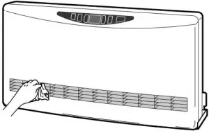
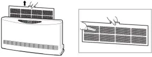
- Clean Air Filter (ONCE A MONTH)
A mesh filter is located on the cabinet’s rear side. Once a month slide the filter up to remove and vacuum it clean.
To remove the air filter, remove the two (2) screws by using a Phillips head screwdriver.
WARNING: NEVER touch the Heat exchanger. It can very hot and cause injury.
SECTION J:
TROUBLESHOOTING
PLEASE NOTE THE FOLLOWING BEFORE REQUESTING FOR HELP FOR REPAIR AND SERVICES
The following conditions can happen during the operation of the unit.
| CONDITION | REASON |
| Does not operate. | – Power outage. – Power supply cord is disconnected. – Child Lock is on. |
| Warm air does not blow. | – Room temperature is higher than the set temperature when the unit is in Auto fan mode. |
| Warm air does not blow and the displayed room temperature is much different from the actual temp. | – Unit is exposed to direct sunlight. – Room thermistor is exposed to a heat source. |
| Cold air blowing out. | – Even if the temperature of the circulation water is 110˚F (43˚C) or more, the wind blowing off may feel cold. |
| Heating performance has declined. | – Clogged or dirty Air filter. – Water pipe flow has been restricted. |
| Occasionally makes “cracking” noise when starting or after shutdown. | – Expansion and shrinkage of plastic and metal parts when they are heated or cooled. Normal |
| “Ticking” noise. | – Noise of relay, valve, and/or Fan motor. Normal. |
| Cannot be operated, beeping noise, and “OFF” are shown on the digital display. | – POWER switch has been turned off while the Child Lock is turned on. |
| Water running noise. | – Hot water is flowing into the unit. Normal |
| Airflow is poor. | – When the temperature of the circulation water is between 100˚F (38˚C) and 110˚F (43˚C), the unit will operate at the low fan speed only. – The Air filter is clogging. |
| The power lamp blinks. | – Indicating that the power failure occurred. To stop the blinking power lamp, press any button once. |
Should problems arise during operation, use this chart to determine the cause and the proper steps to take. Be sure to unplug the unit and allow to cool completely before taking corrective measures.
In the event that the unit should shut down itself, without any action on your part, you should look to the digital display for any of the following error codes.
| ERROR CODE | CAUSE | SOLUTION |
| | Short-circuit of the Water thermistor | Consult your dealer. |
| Electrical power supplied to the unit has abnormal Hz or frequency. (Less than 45 Hz or more than 65 Hz) | Check power supply. Main circuit board malfunction. | |
| The water thermistor is disconnected. | Consult your dealer. | |
| Water temperature too low | Boiler malfunction. Circulation pump malfunction. Consult your dealer. (If the boiler and the circulation pump do not malfunction) | |
| Press |
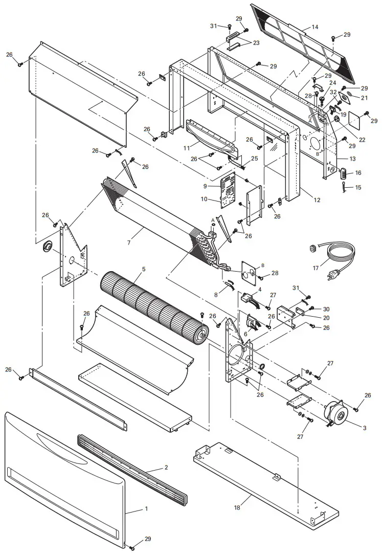
RE. # | PART # | DESCRIPTION | RE. # | PART # | DESCRIPTION | RE. # | PART # | DESCRIPTION |
| 1 | 20477046 | Front panel | 13 | 20477066 | Rear panel | 25 | 20477052 | FFC ribbon cable |
| 2 | 20477032 | Louver assembly | 14 | 20477040 | Filter | 26 | 20474050 | Screw C |
| 3 | 20477069 | Fan motor assembly/ Capacitor | 15 | 20477073 | Room temp. thermistor | 27 | 20474051 | Screw D |
| 4 | 20477003 | Fan capacitor | 16 | 20477075 | Room thermistor cover | 28 | 20476459 | Screw B7 |
| 5 | 20477004 | Fan cross assembly | 17 | 20477035 | Power supply cord | 29 | 20475862 | Screw S2 |
| 6 | 20477017 | Transformer | 18 | 20477029 | Base assembly | 30 | 20477084 | Screw F5 |
| 7 | 20477044 | Heat exchanger assembly | 19 | 20477014 | Switch terminal block | 31 | 20476454 | Screw B4 |
| 8 | 20477074 | Water temp. thermistor | 20 | 20477015 | Power terminal block | 32 | 20477086 | Screw D4 |
| 9 | 20477012 | Main circuit board | 21 | 20477039 | Rubber bushing | 33 | 20477095 | Instruction manual |
| 10 | 20478379 | Fuse 2 (5A) | 22 | 20475850 | Hole plug | 34 | 20477099 | Carton |
| 11 | 20477076 | Lamp circuit board | 23 | 20477062 | Wall bracket | |||
| 12 | 20477020 | Top / Side panel | 24 | 20477051 | Bleeder screw |
LIMITED WARRANTY
TOYOTOMI U.S.A., INC.(“TOYOTOMI”) warrants each product and any parts thereof sold by it to be free from defects in materials or workmanship under normal use and service for TWELVE (12) MONTHS* from the date of delivery to the original purchaser at retail subject to the following terms and conditions :
WHAT has COVERED: Product or any parts thereof which are defective in materials or workmanship.
WHAT IS NOT COVERED :
(1) This warranty does not extend to any defect due to the negligence of others: failure to install, operate, or maintain the unit in accordance with instructions (Installation and Operation instructions are furnished with each new unit); unreasonable use; accidents; alteration, use of unauthorized or non-standardized TOYOTOMI parts and accessories; electrical malfunction, i.e., as resulting from large power surges, short circuit, etc.; incorrect installation; or repair by anyone other than a service facility
specified by TOYOTOMI.
(2) Normal wear and tear of parts, including hoses, wires, filters, and accessories.
(3) This warranty does not cover shipping costs.
WHO has COVERED: The original purchaser at retail.
WHAT WE WILL DO: TOYOTOMI will either repair or replace, at its option, all defective parts free of charge that are covered by this limited warranty on a carry-in basis, to your nearest authorized dealer or distributor of TOYOTOMI.
WHAT YOU MUST DO FOR WARRANTY SERVICE: You must return the defective Product or part to any authorized dealer or distributor of TOYOTOMI with this LIMITED WARRANTY and a copy of your bill of sale or credit card charge receipt or other documents evidencing the date of the Product’s delivery, if service is not available locally, please contact our CUSTOMER RELATIONS DEPARTMENT at :
TOYOTOMI U.S.A., INC.
604 Federal Road, Brookfield, CT 06804
(203)775-1909
THE FOREGOING EXPRESSES ALL OF TOYOTOMI’S OBLIGATIONS AND LIABILITIES WITH RESPECT TO THE QUALITY OF PRODUCT FURNISHED BY IT. ALL OTHER WARRANTIES, EXPRESSED OR IMPLIED, INCLUDING THE WARRANTIES OF MERCHANTABILITY OR FITNESS FOR A PARTICULAR PURPOSE ARE DISCLAIMED. TOYOTOMI SHALL NOT BE LIABLE FOR THE LOSS OF USE OF THE PRODUCT, INCONVENIENCE, LOSS, OR ANY OTHER DAMAGES, DIRECT OR CONSEQUENTIAL ARISING OUT OF, THE USE OF, OR INABILITY TO USE, THE PRODUCT OR DAMAGES RESULTING FROM OR ATTRIBUTABLE TO DEFECTS IN THE PRODUCT.
No one other than TOYOTOMI has authority to extend or modify the terms of this Limited Warranty in any manner whatsoever.
Some states or provinces do not allow the exclusion or limitation of incidental or consequential damages or limitations on how long an implied warranty lasts, so these limitations or exclusions may not apply to you. This Limited Warranty gives you specific legal rights and you may also have other rights that vary from state to state, or province to province.
* In addition to the warranty period stated above, an extended two (2) year warranty (3 years from the date of purchase) is on for the following parts. :
1. Heat Exchanger
NOTE: THE EXTENDED WARRANTY POLICY IS APPLICABLE ONLY FOR THE REPLACEMENT OF THE ORIGINAL FACTORY-INSTALLED PARTS THAT HAVE FAILED WITHIN THE TIME LIMITATIONS AS INDICATED. REPLACEMENT PARTS ARE WARRANTED FOR THE REMAINDER OF THE ORIGINAL PART WARRANTY PERIOD. LABOR IS NOT COVERED BY THE EXTENDED WARRANTY.
![]()
TOYOTOMI U.S.A., INC.
604 Federal Road, Brookfield, CT 06804
www.toyotomiusa.com


