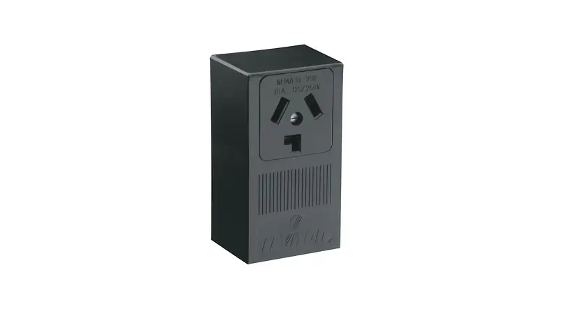
LEVITON PK-A3230-10-00-0B 30 Amp Surface Mtg Receptacle in Black Instruction Manual
SAFETY INSTRUCTIONS
READ ALL INSTRUCTIONS BEFORE USING
![]() WARNING
WARNING
- TO AVOID FIRE, SHOCK, OR DEATH, TURN OFF POWER SUPPLYING THIS EQUIPMENT AND CONFIRM POWER IS OFF, before installing, removing, or servicing this equipment.
- This equipment MUST BE installed and serviced by an electrician.
- To be installed and/or used in accordance with electrical codes and regulations.
- Use ONLY approved fittings and clamps to avoid damage to wires.
- Leviton® circuit breakers MUST BE used with a Leviton circuit breaker enclosure.
- Before providing power to the load center, check all electrical connections and confirm that the wiring is correct.
- Replace all doors and covers before connecting power to this equipment.
- SAVE THESE INSTRUCTIONS.
LIMITED PRODUCT WARRANTY
For Leviton’s limited product warranty, go to www.leviton.com. For a printed copy of the warranty you may call 1-800-323-892
Patents covering this product, if any, can be found on Leviton.com/patents.
INSTALLATION
WARNING: TO AVOID FIRE, SHOCK, OR DEATH, TURN OFF POWER SUPPLYING THIS EQUIPMENT AND CONFIRM POWER IS OFF, before installing, removing, or servicing this equipment.
Step 1: Remove Load Center Door (Optional)
NOTE: The load center door can be removed for easier installation.
a. Lift door (A) upward to remove from hinge (B) (fig. 1).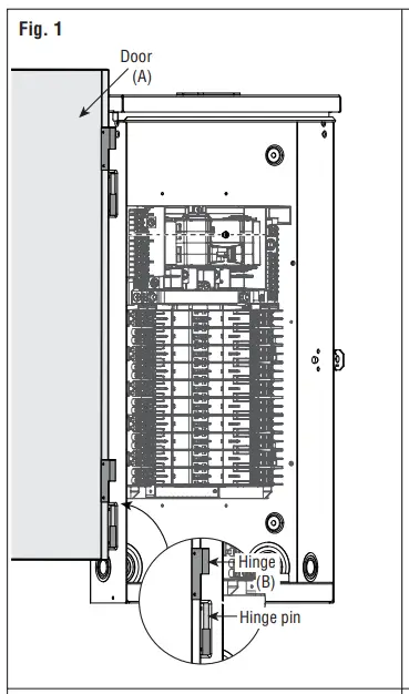
b. When installation is complete, align the door hinge with the hinge pin and insert downward until door is seated
Step 2: Bottom feed applications (Optional)
NOTE: The Leviton® Load Center interior should be inverted for bottom feed applications.
NOTE: Install the closing plate (included) to the overhead opening of the enclosure for bottom feed applications.
NOTE: Before removing any knockouts from the enclosure, consult the local electrical code to determine the knockout requirements.
Remove the mounting screws (C) and the green ground bonding screw (D).
b. Invert the interior (E) and place into slots (F).
c. Replace the mounting screws (C) and green ground bonding screw (D) to secure the interior (fig. 2). Torque all mounting screws to 20 +/- 2 in-lbs.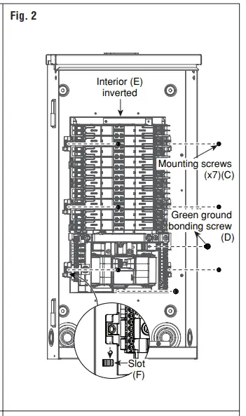
d. To remove knockouts (G), first strike the center of the knockout.
e. Pry each ring (H) up, one at a time, and grip both ends with a pair of pliers.
f. Use the pliers to bend the rings (H), until they disconnect from the enclosure (fig. 3)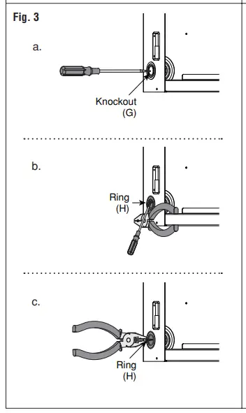
Step 3: Enclosure Mounting
Surface or Semi-Flush Mounting
a. Remove deadfront (W) by loosening the securing screw (X) and lifting the deadfront (W) off the enclsoure (fig. 12).
b. Remove mounting knockouts (I) from the back of the enclosure (fig. 4).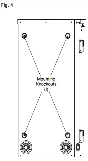
c. Use outdoor approved screws or nails (not provided) in the mounting knockouts (I) to secure the enclosure to the wall.
Step 4: Phase, Neutral, and Ground Conductors
WARNING: Use ONLY approved fittings and clamps to avoid damage to wires
a .Bring the phase (J), neutral (K), and ground (L) conductors into the enclosure through the overhead conduit opening or a bottom-feed knockout.
b. Determine whether or not the application requires the use of a main circuit breaker (M) (fig. 5), or if main lugs (N) (fig. 6) can be used, based on the local electrical codes.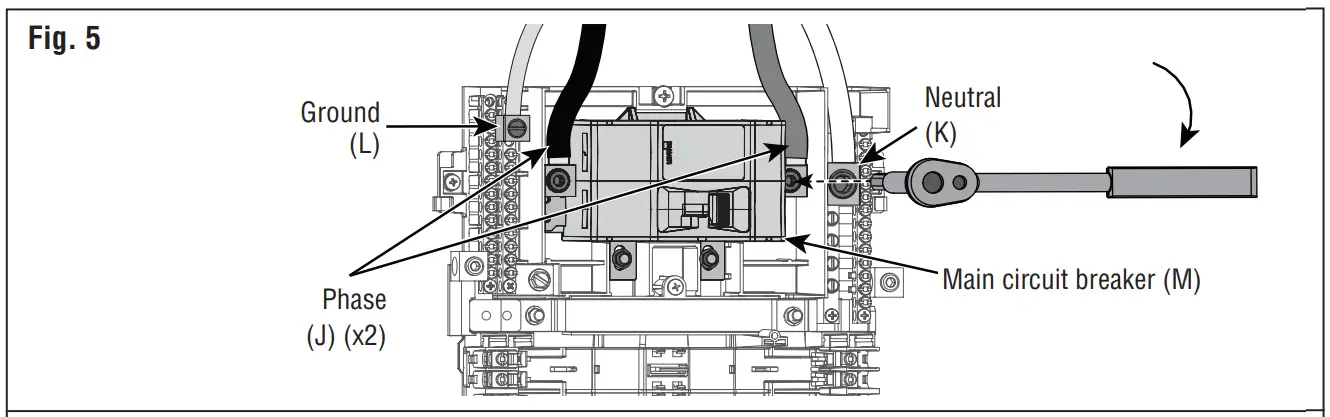
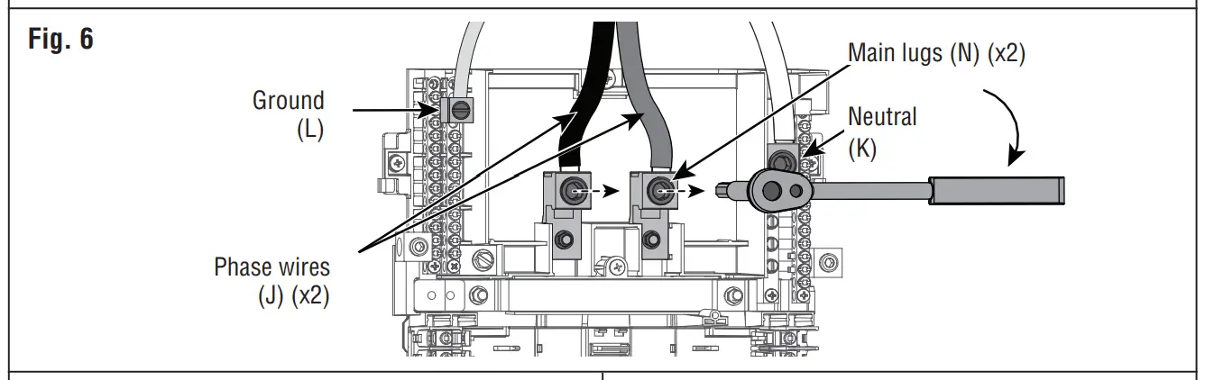
c. Connect the phase (J), neutral (K), and ground (L) conductors to appropriate terminals and torque to spec in the Terminations table (fig. 5 or 6).
d. If installing with a main circuit breaker (M), also install the two (x2) terminal covers (O) that have been provided (fig. 7).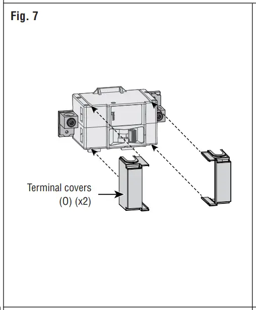
e. When installing this enclosure as the service entrance, the bonding strap (P) MUST BE installed (fig. 8). Torque to 20 in-lbs.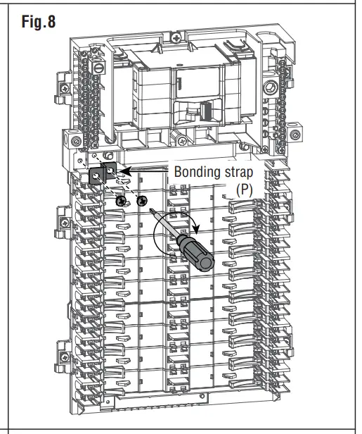
f. When installing this enclosure as a sub panel, DO NOT install the bonding strap (P).
NOTE: For Service Equipment, apply “SERVICE DISCONNECT” label (provided) to trim, near main breaker handle.
NOTE: For Branch Equipment, apply “MAIN” label (provided) to trim, near main breaker handle. Bring the phase (J), neutral (K), and ground (L) conductors into the enclosure through the overhead conduit opening or a bottom-feed knockout.
Step 5: Branch Circuit Breakers
WARNING: Leviton circuit breakers MUST BE used with a Leviton circuit breaker enclosure
a. Strip and connect the load phase (Q) and load neutral (R) wires to the load terminals (S), and ground wire to the ground bus (T) of the circuit breaker enclosure (fig. 9). Strip wires and torque load terminals to spec in the Terminations table.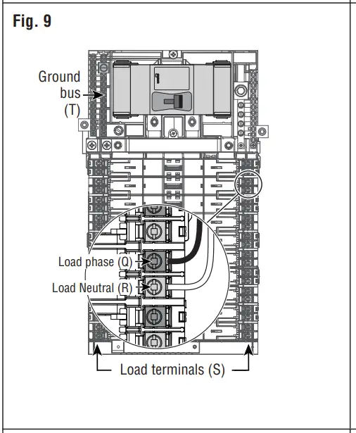
NOTE: Ensure that the main breaker is in the OFF position before installing any branch circuit breakers.
NOTE: Ensure that all branch circuit breakers are in the OFF position before installing into the panel.
b. Align the hooks and guides (U) of the branch circuit breaker with the panel and press until breaker snaps into place (fig. 10).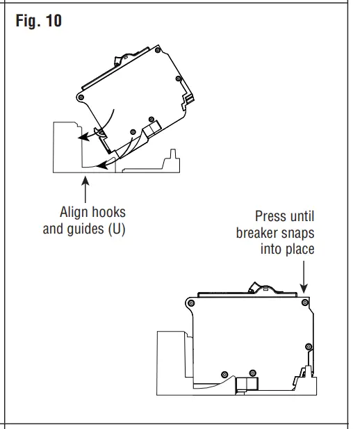
Step 6: Installing Deadfront
NOTE: Twist-outs (V) must be removed for each position that contains a branch circuit breaker. Fill any unused open spaces in cover using filler plates.
a. To remove twist-outs (V), first strike with a screwdriver, and then twist with pliers until detached (fig. 11).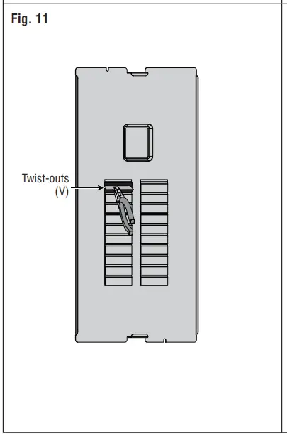
b. Install deadfront (W) by sliding it inward above the side wall protrusions on each side at a 45-degree angle, until bottom portion of the deadfront (W) is seated into enclosure (fig. 12).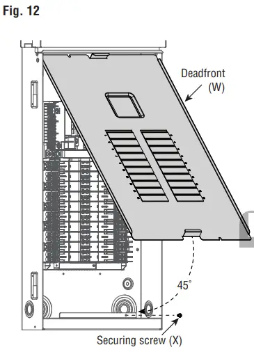
c. Secure the bottom of the deadfront (W) with the securing screw (X).
d. Apply circuit directory labels on the back of the door.
Step 7: Complete the Installation
WARNING: Before providing power to the load center, check all electrical connections and confirm that the wiring is correct.
WARNING: Replace all doors and covers before connecting power to this equipment.
Terminations
| Termination Point | Wire Material | Wire Gange | Stdp Length | Torque |
| Main Breaker | er / Copp —Aluminum | *3 AWG – 300 MCM | 1.0 in. | 250 in.-lbs. |
| Main Lug | Atc:umpllrm/ | *6 AWG – 300 MCM | 1.0 in. | 375 in.-lbs. |
| Neutral Line | Copper / Copp —Aluminum | *6 AWG – 300 MCM | 1.5 in. | 375 in.-lbs |
| Ground | Copper) Aluminum | 04 AWG – 2/0 AWG | 0.75 in. | 50 in.-lbs |
| Load Phase (brass) & Load Neutral(silver) | Copper | (1)14 AWG – *8 AWG. Stranded | 0.4 in. | 45 in.-lbs |
| (1)*10 AWG. Solid or Stranded | 35 in.-lbs | |||
| (2) 114 AWG – #10 AWG. Solid | 35 in.-lbs | |||
| (1) *12 AWG – #14 AWG. Solid or Stranded | 25 in.-lbs. | |||
| (2) 114 AWG or (2)4112 AWG. Stranded | 25 in.-lbs. | |||
| Aluminum | (1) 14 AWG – 06 AWG. Stranded | 45 in.-lbs | ||
| (1)18 AWG. Stranded | 35 in.-lbs | |||
| (2) #12 AWG – #10 AWG. Solid | 35 in.-lbs | |||
| (1)*10 AWG- 012 AWG, Solid | 25 in.-lbs. | |||
| (2) 112 AWG or (2) #10 AWG, Solid | 25 in.-lbs. | |||
| Neutral & Equipment Ground Bar | Copper/ Aluminum | (1) /6 AWG – 04 AWG. Stranded | 0.5 in | 35 in.-lbs |
| (1)18 AVVG• Stranded | 25 in.-lbs | |||
| (1) *14 AWG- t10 AWG Solid or Stranded | 20 in.-lbs | |||
| Copper | (2) *14 AWG -170 AWG. Solid or Stranded | 25 in.-lbs | ||
| (1) #14 AWG and (1) *12 AWG. Solid | 25 in.-lbs | |||
| (1) #14 AWG and (1) *10 AWG. Solid or Stranded | 25 in.-lbs | |||
| (1)6’12 AWG and (1) 110 AWG. Solid | 25 in.-lbs | |||
| Aluminum | (2) #12 AWG – #10 AWG. Solid | 20 in.-lbs | ||
| (1) i12 AWG and (1) *10 AWG. Solid | 20 in.-lbs | |||
| Neutral Bar | Copper/ Aluminum | *4 AWG – *1 AWG. Stranded | 0.5 in | 50 in.-lbs |
| *8 AWG – *6 AWG. Stranded | 30 in.-lbs | |||
| Copper | #14 AWG – #10 AWG. Solid or Stranded | 30 in.-lbs | ||
| Aluminum | *12 AWG – *10 AWG. Solid | 30 in.-lbs |
Costumer Support
For Technical Assistance,
call: 1-800-824-3005 (USA Only) or 1-800-405-5320 (Canada Only) www.leviton.com