![]() 4A6H6 Split System Heat Pumps
4A6H6 Split System Heat Pumps
Installation Guide 11-BC39D1-1E-EN
Installer’s Guide
Heat Pumps 4A6H6
4A6H6 Split System Heat Pumps
ALL phases of this installation must comply with NATIONAL, STATE AND LOCAL CODES
IMPORTANT — This Document is customer property and is to remain with this unit. Please return to service information pack upon completion of work.
These instructions do not cover all variations in systems or provide for every possible contingency to be met in connection with the installation. Should further information be desired or should particular problems arise which are not covered sufficiently for the purchaser’s purposes, the matter should be referred to your installing dealer or local distributor.
Note: The manufacturer recommends installing only approved matched indoor and outdoor systems. All of the manufacture’s split systems are A.H.R.I. rated only with TXV/EEV indoor systems. Some of the benefits of installing approved matched indoor and outdoor split systems are maximum efficiency, optimum performance and the best overall system reliability.
Safety
![]() WARNING
WARNING
This information is intended for use by individuals possessing adequate backgrounds of electrical and mechanical experience. Any attempt to repair a central air conditioning product may result in personal injury and/or property damage. The manufacture or seller cannot be responsible for the interpretation of this information, nor can it assume any liability in connection with its use.![]() WARNING
WARNING
These units use R-410A refrigerant which operates at 50 to 70% higher pressures than R-22. Use only R-410A approved service equipment. Refrigerant cylinders are painted a “Rose” color to indicate the type of refrigerant and may contain a “dip” tube to allow for charging of liquid refrigerant into the system. All R-410A systems use a POE oil that readily absorbs moisture from the atmosphere. To limit this “hygroscopic” action, the system should remain sealed whenever possible. If a system has been open to the atmosphere for more than 4 hours, the compressor oil must be replaced. Never break a vacuum with air and always change the driers when opening the system for component replacement. For specific handling concerns with R-410A and POE oil reference Retrofit Bulletins SS-APG006-EN and APP-APG012-EN.
![]() WARNING
WARNING
UNIT CONTAINS R-410A REFRIGERANT!
R-410A operating pressures exceed the limit of R-22.
Proper service equipment is required. Failure to use proper service tools may result in equipment damage or personal injury.
SERVICE
USE ONLY R-410A REFRIGERANT AND APPROVED POE COMPRESSOR OIL.
![]() WARNING
WARNING
Extreme caution should be exercised when opening the Liquid Line Service Valve. Turn counterclockwise until the valve stem just touches the rolled edge. No torque is required. Failure to follow this warning will result in abrupt release of system charge and may result in personal injury and /or property damage.
![]() WARNING
WARNING
LIVE ELECTRICAL COMPONENTS!
During installation, testing, servicing, and troubleshooting of this product, it may be necessary to work with live electrical components. Failure to follow all electrical safety precautions when exposed to live electrical components could result in death or serious injury.
![]() CAUTION
CAUTION
If using existing refrigerant lines make certain that all joints are brazed, not soldered.![]() CAUTION
CAUTION
Scroll compressor dome temperatures may be hot. Do not touch the top of compressor; it may cause minor to severe burning.
Unit Location Considerations
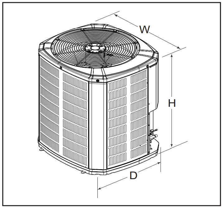
2.1 Unit Dimensions and Weight
Table 2.1
| Unit Dimensions and Weight | ||
| Models | H x D x W (in) | Weight* (lb) |
| 4A6H6024N | 41 x 34 x 37 | 236 |
| 4A6H6036N | 45 x 34 x 37 | 257 |
| 4A6H6048N | 45 x 34 x 37 | 292 |
| 4A6H6060N | 45 x 34 x 37 | 293 |
| 4A6H6018H | 40 x 30 x 33 | 174 |
| 4A6H6024H | 33 x 30 x 33 | 174 |
| 4A6H6030H | 37 x 34 x 37 | 198 |
| 4A6H6036H | 37 x 34 x 37 | 199 |
| 4A6H6042H | 45 x 34 x 37 | 227 |
| 4A6H6048H | 45 x 34 x 37 | 250 |
| 4A6H6060H | 45 x 34 x 37 | 251 |
| * Weight values are estimated. | ||
When mounting the outdoor unit on a roof, be sure the roof will support the unit’s weight.
Properly selected isolation is recommended to alleviate sound or vibration transmission to the building structure.
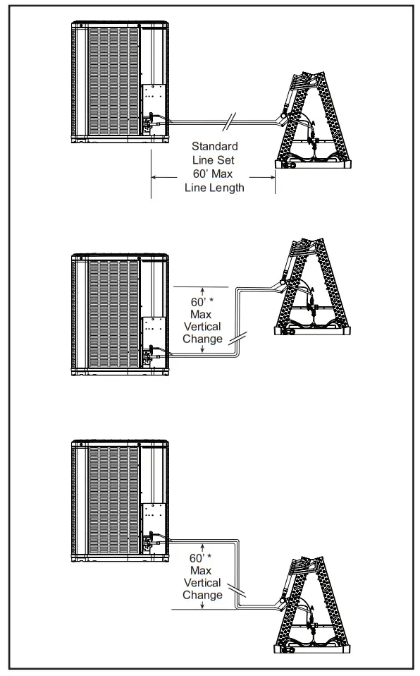
2.2 Refrigerant Piping Limits
- The maximum length of refrigerant lines from outdoor to indoor unit should NOT exceed sixty (60) feet.
- The maximum vertical change should not exceed sixty (60) feet*.
- Service valve connection diameters are shown in Table 5.1.
Note: For line lengths greater than sixty (60) feet, Refer to Refrigerant Piping Application Guide, SS-APG006-EN or Refrigerant Piping Software Program, 32-3312-03 (or latest revision).
2.3 Suggested Locations for Best Reliability
Ensure the top discharge area is unrestricted for at least five (5) feet above the unit.
Three (3) feet clearance must be provided in front of the control box (access panels) and any other side requiring service.
Do not locate close to bedrooms as operational sounds may be objectionable.
Avoid locations such as near windows where condensation and freezing defrost vapor can annoy a customer.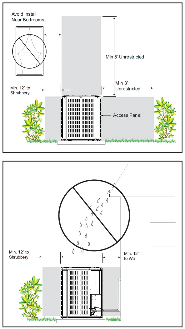
Position the outdoor unit a minimum of 12” from any wall or surrounding shrubbery to ensure adequate airflow.
Outdoor unit location must be far enough away from any structure to prevent excess roof runoff water or icicles from falling directly on the unit.
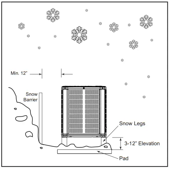
2.4 Cold Climate Considerations
NOTE: It is recommended that these precautions be taken for units being installed in areas where snow accumulation and prolonged below freezing temperatures occur.
- Units should be elevated 3-12 inches above the pad or roof top, depending on local weather. This additional height will allow drainage of snow and ice melted during defrost cycle prior to its refreezing. Ensure that drain holes in unit base pan are not obstructed preventing draining of defrost water.
- If possible, avoid locations that are likely to accumulate snow drifts. If not possible, a snow drift barrier should be installed around the unit to prevent a build-up of snow on the sides of the unit.

2.5 Coastal Considerations
If installed within one mile of salt water, including seacoasts and inland waterways, models without factory supplied Seacoast Salt Shields require the addition of BAYSEAC001 (Seacoast Kit) at installation time.
Unit Preparation
3.1 Prepare The Unit For Installation
STEP 1 – Check for damage and report promptly to the carrier any damage found to the unit.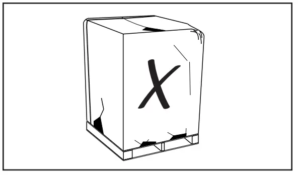
STEP 2 – To remove the unit from the pallet, remove tabs by cutting with a sharp tool.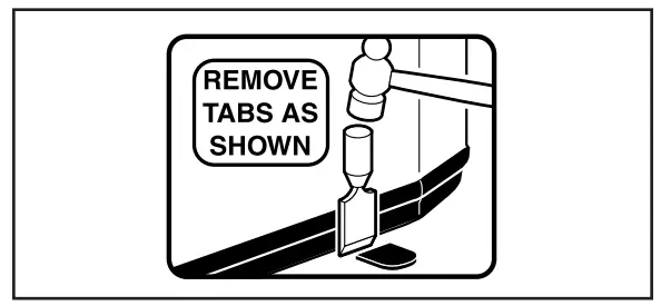
Setting the Unit
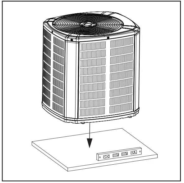
4.1 Pad Installation
When installing the unit on a support pad, such as a concrete slab, consider the following:
- The pad should be at least 1” larger than the unit on all sides.
- The pad must be separate from any structure.
- The pad must be level.
- The pad should be high enough above grade to allow for drainage.
- The pad location must comply with National, State, and Local codes.
Refrigerant Line Considerations
5.1 Refrigerant Line and Service Valve Connection Sizes
Table 5.1
| Line Sizes | Service Valve Connection Sizes | |||
| Model | Vapor Line | Liquid Line | Vapor Line Connection | Liquid Line Connection |
| 4A6H6024N | 5/8 | 3/8 | 3/4 | 3/8 |
| 4A6H6036N | 3/4 | 3/8 | 3/4 | 3/8 |
| 4A6H6048N | 7/8 | 3/8 | 7/8 | 3/8 |
| 4A6H6060N | 1-1/8 | 3/8 | 7/8 | 3/8 |
| Alternate Line Sizes | Line Sizes | Service Valve Connection Sizes | ||
| Model | Vapor Line | Liquid Line | Vapor Line Connection | Liquid Line Connection |
| 4A6H6024N | 3/4 | 3/8 | 3/4 | 3/8 |
| 4A6H6036N | 5/8 | 3/8 | 3/4 | 3/8 |
| 7/8 | 3/8 | 3/4 | 3/8 | |
| 4A6H6048N | 3/4 | 3/8 | 7/8 | 3/8 |
| 4A6H6060N | 3/4 | 3/8 | 7/8 | 3/8 |
| 7/8 | 3/8 | 7/8 | 3/8 | |
| Line Sizes | Service Valve Connection Sizes | |||
| Model | Vapor Line | Liquid Line | Vapor Line Connection | Liquid Line Connection |
| 4A6H6018H | 3/4 | 3/8 | 3/4 | 3/8 |
| 4A6H6024H | 3/4 | 3/8 | 3/4 | 3/8 |
| 4A6H6030H | 3/4 | 3/8 | 3/4 | 3/8 |
| 4A6H6036H | 7/8 | 3/8 | 3/4 | 3/8 |
| 4A6H6042H | 7/8 | 3/8 | 7/8 | 3/8 |
| 4A6H6048H | 7/8 | 3/8 | 7/8 | 3/8 |
| 4A6H6060H | 1-1/8 | 3/8 | 7/8 | 3/8 |
5.2 Factory Charge
The outdoor condensing units are factory charged with the system charge required for the outdoor condensing unit, ten (10) feet of tested connecting line, and the smallest rated indoor evaporative coil match. Always verify proper system charge via sub cooling (TXV/EEV) or superheat (fixed orifice) per the unit nameplate.
5.3 Required Refrigerant Line Length
Determine required line length and lift. You will need this later in STEP 2 of Section 14.
Total Line Length = __________ Ft.
Total Vertical Change (lift) = __________ Ft.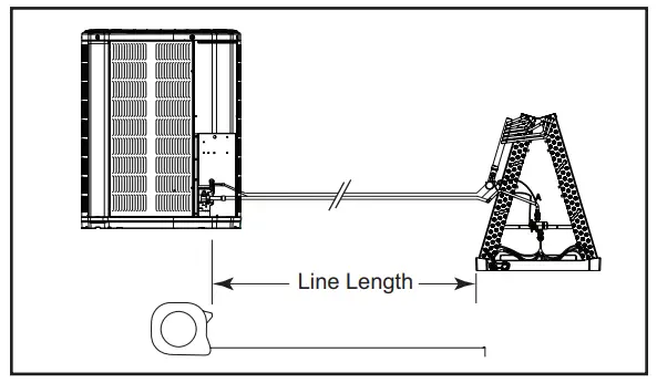
5.4 Refrigerant Line Insulation
Important: The Vapor Line must always be insulated. DO NOT allow the Liquid Line and Vapor Line to come in direct (metal to metal) contact.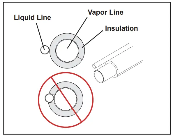
5.5 Reuse Existing Refrigerant Lines![]() CAUTION
CAUTION
If using existing refrigerant lines make certain that all joints are brazed, not soldered.
For retrofit applications, where the existing indoor evaporator coil and/or refrigerant lines will be used, the following precautions should be taken:
• Ensure that the indoor evaporator coil and refrigerant lines are the correct size.
• Ensure that the refrigerant lines are free of leaks, acid, and oil.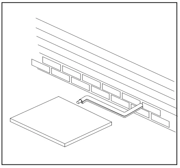
Refrigerant Line Routing
6.1 Precautions
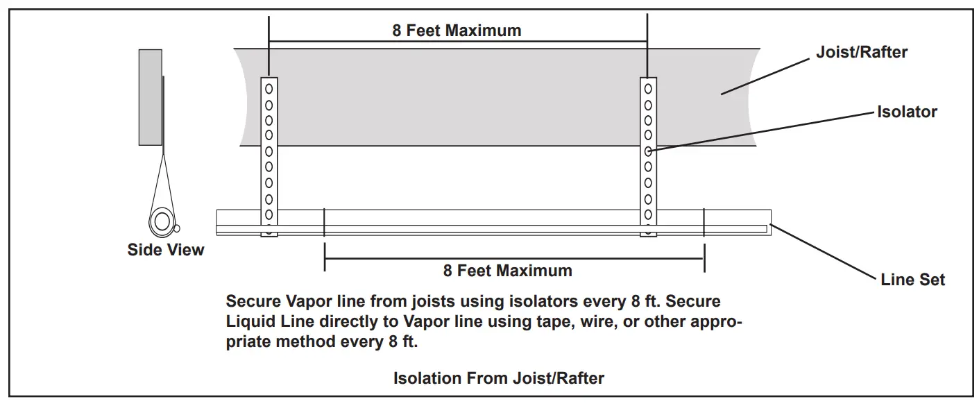
Important: Take precautions to prevent noise within the building structure due to vibration transmission from the refrigerant lines.Comply with National, State, and Local Codes when isolating line sets from joists, rafters, walls, or other structural elements.
For Example:
- When the refrigerant lines have to be fastened to floor joists or other framing in a structure, use isolation type hangers.
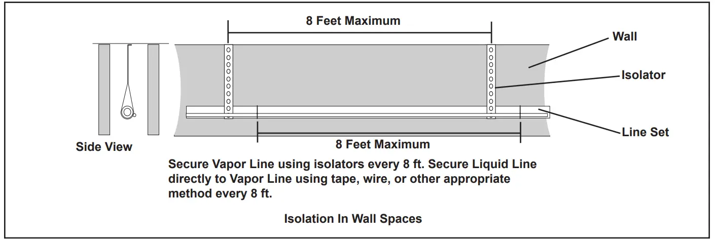
- Isolation hangers should also be used when refrigerant lines are run in stud spaces or enclosed ceilings.
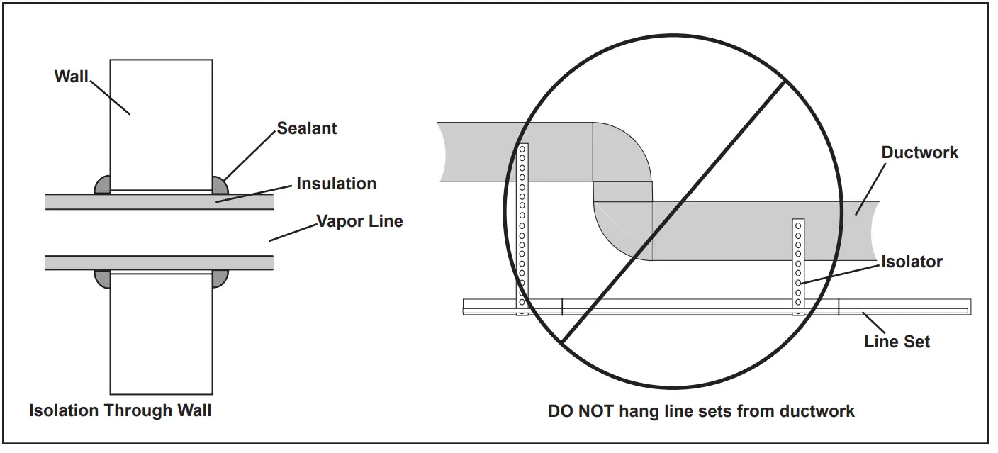
- Where the refrigerant lines run through a wall or sill, they should be insulated and isolated.
- Isolate the lines from all ductwork.
- Minimize the number of 90º turns.
Refrigerant Line Brazing
7.1 Braze The Refrigerant Lines
STEP 1 – Remove caps or plugs. Use a deburring tool to deburr the pipe ends. Clean both internal and external surfaces of the tubing using an emery cloth.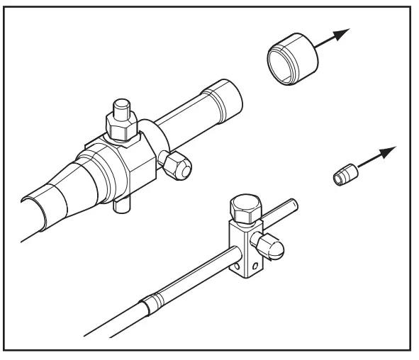 STEP 2 – Remove the pressure tap cap and valve cores from both service valves.
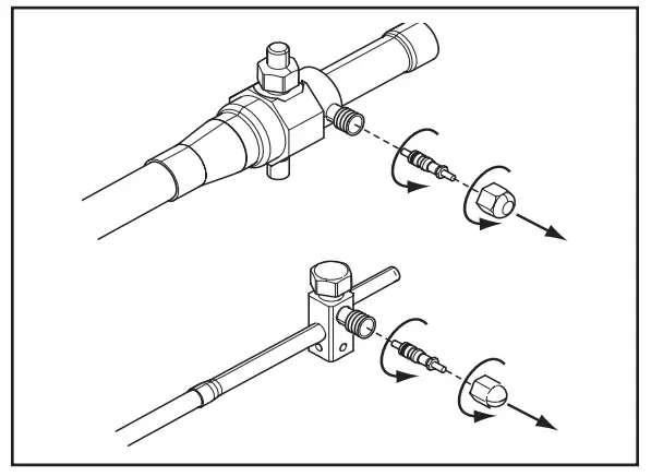 STEP 3 – Purge the refrigerant lines and indoor coil with dry nitrogen.
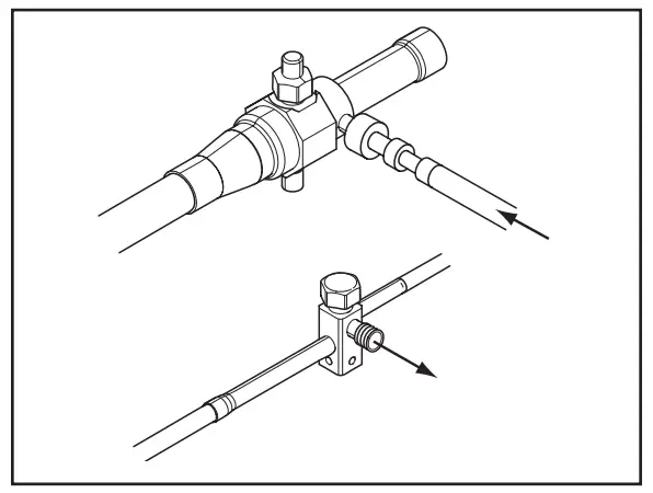
STEP 4 – Wrap a wet rag around the valve body to avoid heat damage and continue the dry nitrogen purge.
Braze the refrigerant lines to the service valves.
For units shipped with a field-installed external drier, check liquid line filter drier’s directional flow arrow to confirm correct direction of refrigeration flow (away from outdoor unit and toward evaporator coil) as illustrated. Braze the filter drier to the Liquid Line.
Continue the dry nitrogen purge. Do not remove the wet rag until all brazing is completed.
Important: Remove the wet rag before stopping the dry nitrogen purge.
Note: Install drier in Liquid Line.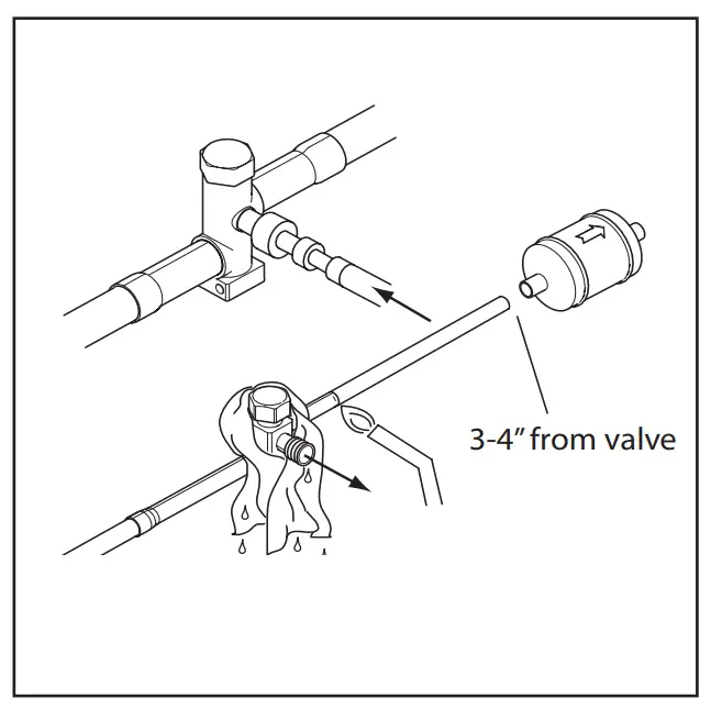 NOTE: Precautions should be taken to avoid Precautions should be taken to avoid heat damage to baseman during brazing. It is heat damage to baseman during brazing. It is recommended to keep the flame directly off the baseman.
STEP 5 – Replace the pressure tap valve cores after the service valves have cooled.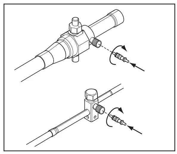
Refrigerant Line Leak Check
8.1 Check For Leaks
STEP 1 – Pressurize the refrigerant lines and evaporator coil to 150 PSIG using dry nitrogen.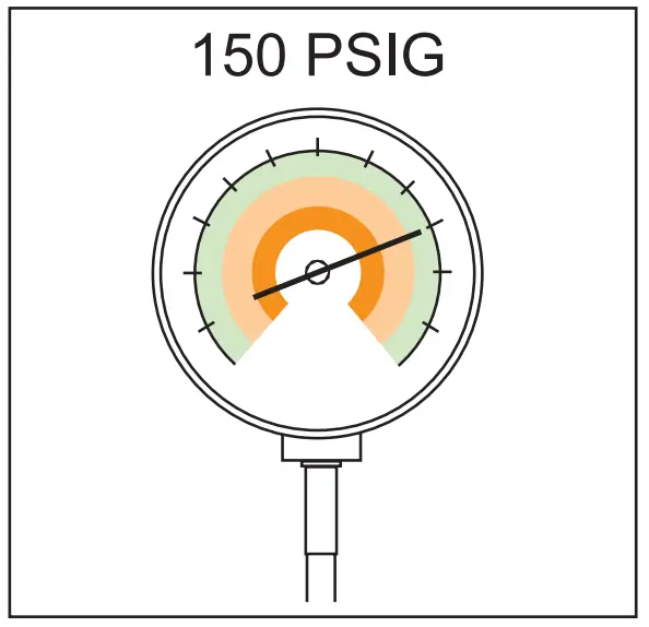
STEP 2 – Check for leaks by using a soapy solution or bubbles at each brazed location.
Remove nitrogen pressure and repair any leaks before continuing.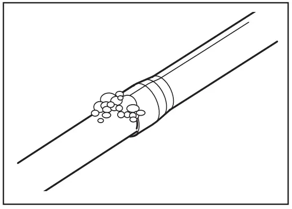
Evacuation
9.1 Evacuate the Refrigerant Lines and Indoor Coil
Important: Do not open the service valves until the refrigerant lines and indoor coil leak check and evacuation are complete.
STEP 1 – Evacuate until the micron gauge reads no higher than 350 microns, then close off the valve to the vacuum pump.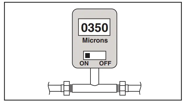
STEP 2 – Observe the micron gauge. Evacuation is complete if the micron gauge does not rise above 500 microns in one (1) minute.
Once evacuation is complete blank off the vacuum pump and micron gauge, and close the valves on the manifold gauge set.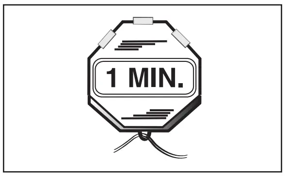
Service Valves
10.1 Open the Gas Service Valve
Important: Leak check and evacuation must be completed before opening the service valves.
NOTE: Do not vent refrigerant gases into the atmosphere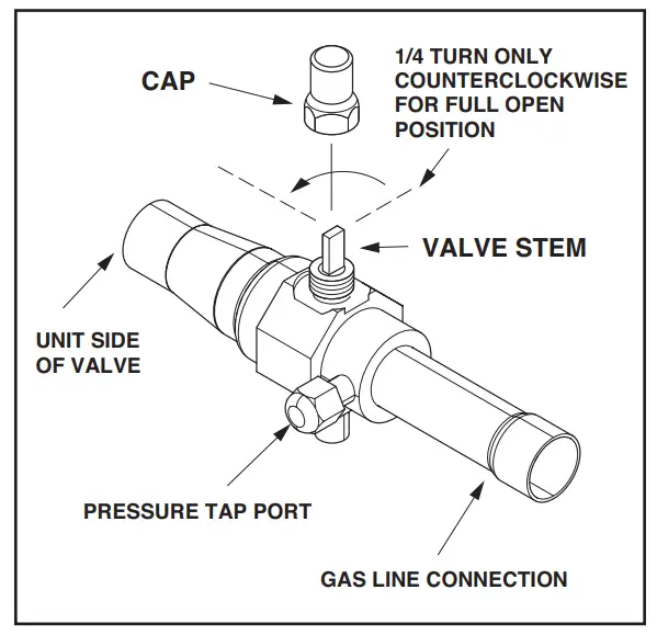 STEP 1 – Remove valve stem cap.
STEP 2 – Using an adjustable wrench, turn valve stem 1/4 turn counterclockwise to the fully open position.
STEP 3 – Replace the valve stem cap to prevent leaks. Tighten finger tight plus an additional 1/6 turn.
10.1 Open the Liquid Service Valve
WARNING
Extreme caution should be exercised when opening the Liquid Line Service Valve. Turn counterclockwise until the valve stem just touches the rolled edge. No torque is required. Failure to follow this warning will result in abrupt release of system charge and may result in personal injury and /or property damage.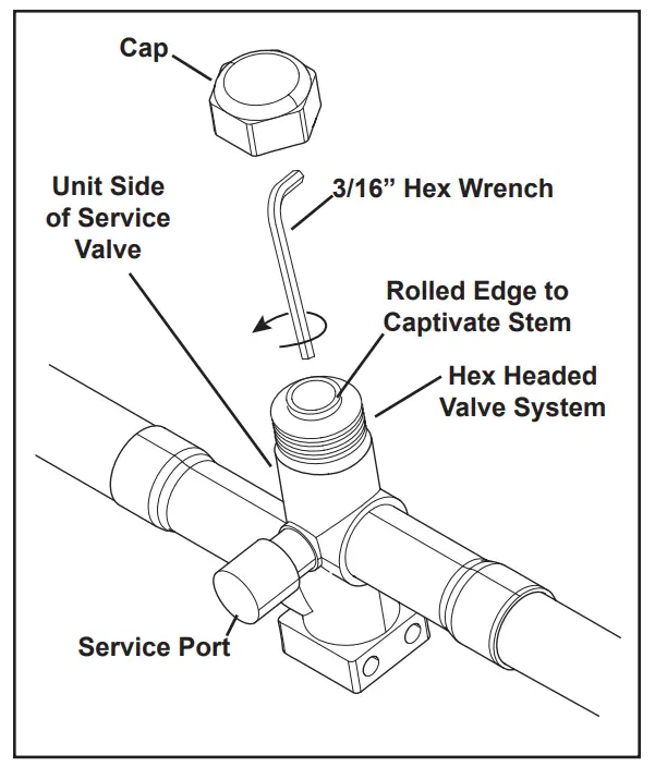
Important: Leak check and evacuation must be completed before opening the service valves.
STEP 1 – Remove service valve cap.
STEP 2 – Fully insert 3/16” hex wrench into the stem and back out counterclockwise until valve stem just touches the rolled edge (approximately five (5) turns.)
STEP 3 – Replace the valve cap to prevent leaks. Tighten finger tight plus an additional 1/6 turn.
Electrical – Low Voltage
11.1 Low Voltage Maximum Wire Length
Table 11.1 defines the maximum total length of low voltage wiring from the outdoor unit, to the indoor unit, and to the thermostat.
Table 11.1
24 VOLTS | |
| WIRE SIZE | MAX. WIRE LENGTH |
| 18 AWG | 150 Ft. |
| 16 AWG | 225 Ft. |
| 14 AWG | 300 Ft. |
11.2 Low Voltage Hook-up Diagrams
For 024N – 060N Models:
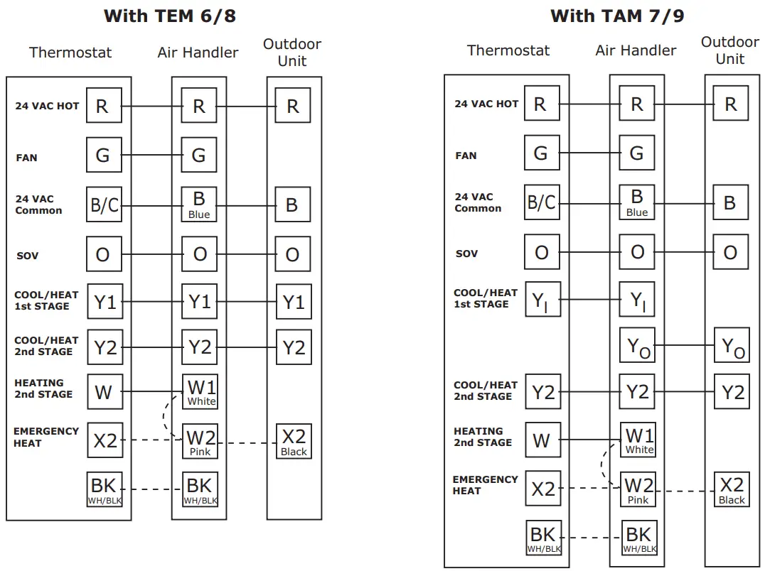
- Units with pigtails require wisents for connections.
- In systems with multiple stages of electric heat, jumper W1 and W2 together if comfort control has only one stage of heat.
** TEM6 only – When using a BK enabled comfort control, cut BK jumper and bypass Y1 and Y2 at the air handler. Connect BK from comfort control to BK of the air handler - TAM7 only – When using a BK enabled comfort control, cut BK jumper on the AFC and connect BK from comfort control to BK of the air handler. TAM7 DIP switches must be configured for “HP: 2-Stage/1 Compressor”.
For 018H – 060H Models:
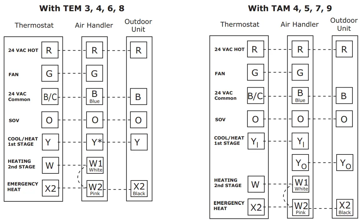
- Units with pigtails require wisents for connections.
- In AC systems for multiple stages of electric heat, jumper W1 and W2 together if comfort control has only one stage of heat.
* Y2 for TEM6
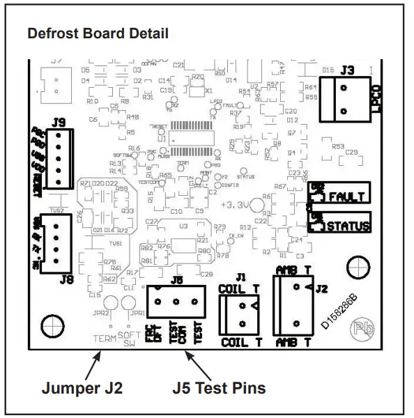
11.3 Defrost Control
Defrost controls have a selectable termination temperature. As shipped, defrost will terminate at 47°F. For a higher termination temperature, cut Jumper J2 to achieve 70°F. See Service Facts shipped in the outdoor unit for more information.
Pin Identification on J5 (See Illustration)
- TEST_COMMON (Shorting to FRC_DFT causes the control to initiate Forced Defrost. Leaving this pin open results in the normal mode of operation.)
- FRC_DFT = Forced Defrost (Short TEST_ COMMON to this pin for two (2) seconds to initiate a forced defrost. Remove the short after defrost initiates.)
Defrost Control Checkout
Normal operation requires:
- Status LED on board flashing 1 time/second in standby or 2 times/second with a call for heating or cooling.
- 24V AC between R & B
- 24V AC between Y, Y0 & B with unit operating
- Defrost initiation when FRC_DFT pin is shorted to TEST_COMMON pin.
If a defrost control problem is suspected, refer to the service information in control box.
Electrical – High Voltage
12.1 High Voltage Power Supply
![]() WARNING
WARNING
LIVE ELECTRICAL COMPONENTS!
During installation, testing, servicing, and troubleshooting of this product, it may be necessary to work with live electrical components. Failure to follow all electrical safety precautions when exposed to live electrical components could result in death or serious injury.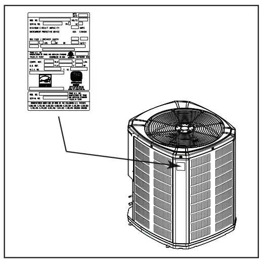
The high voltage power supply must agree with the equipment nameplate.
Power wiring must comply with national, state, and local codes.
Follow instructions on unit wiring diagram located on the inside of the control box cover and in the Service Facts document included with the unit.
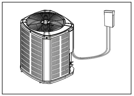
12.2 High Voltage Disconnect Switch
Install a separate disconnect switch at the outdoor unit. For high voltage connections, flexible electrical conduit is recommended whenever vibration transmission may create a noise problem within the structure.
12.3 High Voltage Ground
Ground the outdoor unit per national, state, and local code requirements.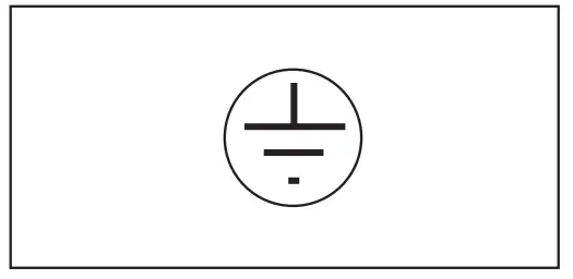
Start Up
13.1 System Start Up
STEP 1 – Ensure Sections 7 through 12 have been completed.
STEP 2 – Set System Thermostat to OFF.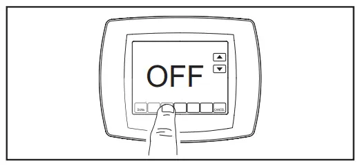
STEP 3 – Turn on disconnect(s) to apply power to the indoor and outdoor units.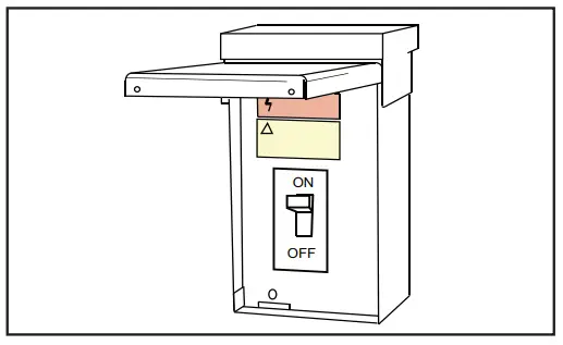
STEP 4 – Wait one (1) hour before starting the unit if compressor crankcase heater accessory is used and the Outdoor Ambient is below 70ºF.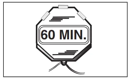
STEP 5 – Set system thermostat to ON.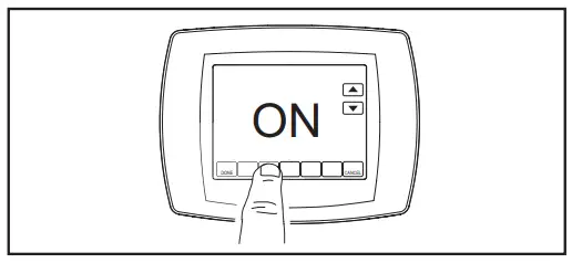
System Charge Adjustment
14.1 Temperature Measurements
STEP 1 – Check the outdoor temperatures.
Sub cooling (in cooling mode) is the only recommended method of charging above 55º F ambient outdoor temperature. See Section 14.2.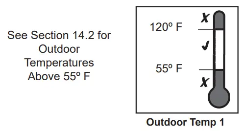
For outdoor temperatures below 55º F, see Section 14.3.
Note: It is important to return in the spring or summer to accurately charge the system in the cooling mode when outdoor ambient temperature is above 55ºF.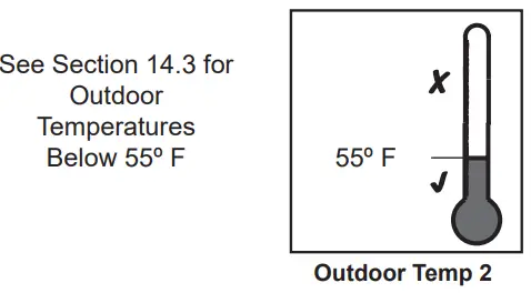 For best results the indoor temperature should be kept between 70º F to 80º F.
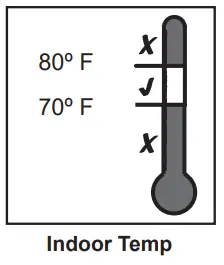
14.2 Sub cooling Charging in Cooling (Above 55º F Outdoor Temp.)
STEP 1 – Use the refrigerant line total length and lift measurements from Section 5.3.
Total Line Length = __________ Ft.
Vertical Change (Lift) = __________ Ft.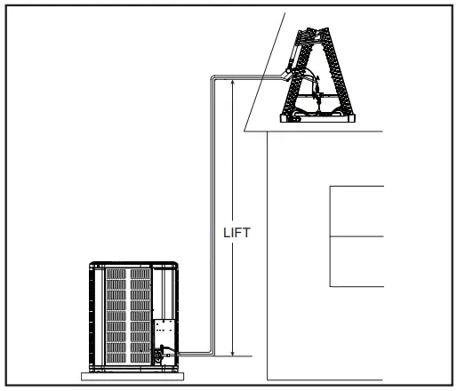
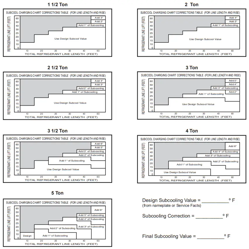
STEP 2 – Determine the final sub cooling value using total Line Length and Lift measured in STEP 1 and the charts below.
For 024N – 060N Models: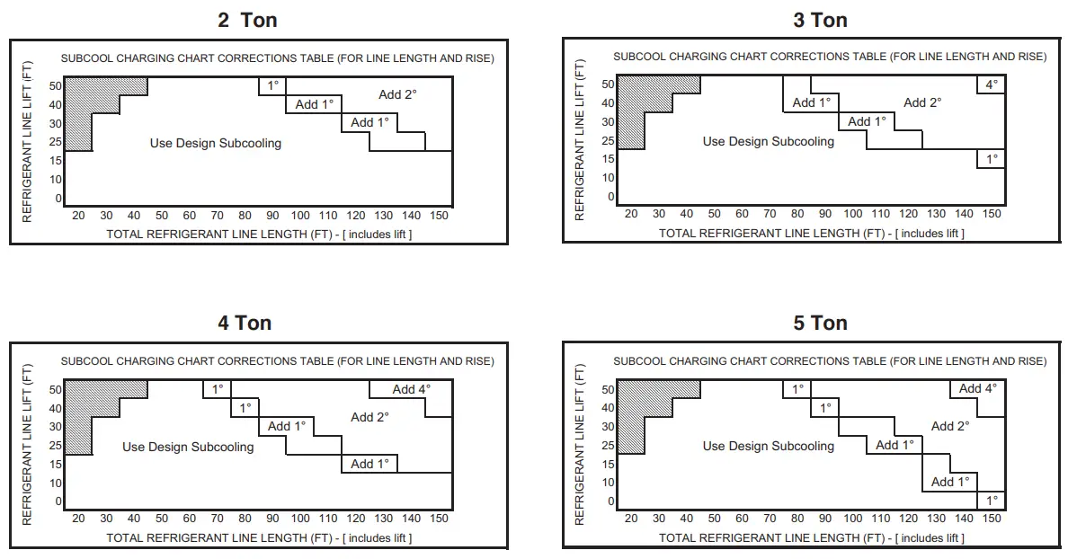
Design Sub cooling Value = __________º F (from nameplate or Service Facts)
Sub cooling Correction = __________º F
Final Sub cooling Value = __________º F
For 018H – 060H Models:
STEP 3 – Stabilize the system by operating for a minimum of 20 minutes.
At startup, or whenever charge is removed or added, the system must be operated for a mini- mum of 20 minutes to stabilize before accurate measurements can be made.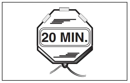
STEP 4 – Measure the liquid line temperature and pressure at the outdoor unit’s service valve.
Measured Liquid Line Temp = __________ º F
Liquid Gage Pressure = __________ PSIG
Final Sub cooling Value = __________ º F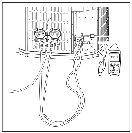
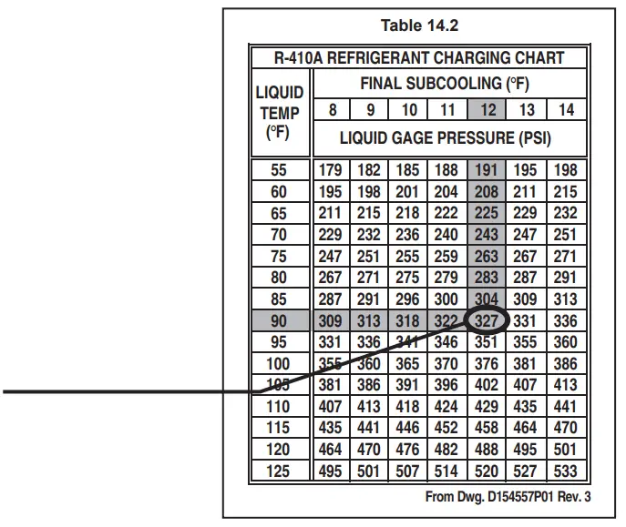
STEP 5 – Use the final sub cooling value, refrigerant temperature and pressure from STEP 4, to determine the proper liquid gage pressure using Table 14.2.
Example: Assume a 12º F Final Sub cooling value and liquid temp of 90º F.
- Locate 12º F Final Sub cooling in Table 14.2.
- Locate the Liquid Temperature (90º F) in the left column.

- The Liquid Gage Pressure should be approximately 327 PSIG. (This is the shown as the intersection of the Final Sub cooling column and the Liquid Temperature row.
Special sub cooling for application with TEM6 AH
| Outdoor Unit Model No. | Indoor Unit Model No. | Sub cooling |
| 4A6H6024H1000A | TEM6A0C36H31 | 13º |
STEP 6 – Adjust refrigerant level to attain proper gage pressure.
Add refrigerant if the Liquid Gage Pressure is lower than the chart value.
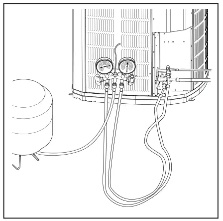
- Connect gages to refrigerant bottle and unit as illustrated.
- Purge all hoses.
- Open bottle.

- Stop adding refrigerant when liquid line temperature and Liquid Gage
Pressure matches the charging chart Final Subcoupling value.
Recover refrigerant if the Liquid Gage Pressure is higher than the chart value.
STEP 7 – Stabilize the system.
- Wait 20 minutes for the system condition to stabilize between adjustments.
Note: When the Liquid Line Temperature and Gage Pressure approximately match the chart, the system is properly charged.
- Remove gages.
- Replace service port caps to prevent leaks. Tighten finger tight plus an additional 1/6 turn.
STEP 8 – Verify typical performance.
Refer to System Pressure Curves in the Service
Facts to verify typical performance.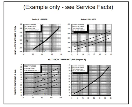
STEP 9 – Record System Information for reference.
Record system pressures and temperatures after charging is complete.
Outdoor model number = _________________
Measured Outdoor Ambient = __________ º F
Measured Indoor Ambient = __________ º F
Measured Liquid Line Temp = __________ º F
Measured Suction Line Temp = __________ º F
Liquid Gage Pressure = __________ PSIG
Suction Gage Pressure = __________ PSIG
14.3 Sub cooling Charging Below 55º F Outdoor Temp. (In Heating Only)
The Sub cooling Charging method in cooling is not recommended below 55º F outdoor temperature.
The only recommended method of charging at outdoor temperatures below 55º F is weighing in the charge in heating mode.
STEP 1 – Determine additional charge.
Note: The nameplate charge value represents the amount of refrigerant shipped in the outdoor unit and is compatible with 10 feet of AHRI rated refrigerant lines and the smallest AHRI rated coil.
Using the method below, find the charge associated with the additional length of tubing above 10 ft. and record it below.
Calculating Charge Using the Weigh-In Method
STEP 1 – Measure in feet the distance between the outdoor unit and the indoor unit. (Include the entire length of the line from the service valve to the IDU.) Subtract 10 ft from this entire length and record on line 1.
STEP 2 – Enter the charge multiplier (0.6 oz/ft).
Each linear foot of interconnecting tubing requires the addition of 0.6 oz of refrigerant.
STEP 3 – Multiply the total length of refrigerant tubing (Line 1) times the value on Step 2. Record the result on Line 3 of the Worksheet.
STEP 4 – This is the amount of refrigerant to weigh-in prior to opening the service valves.
Weigh-In Method can be used for the initial installation, or anytime a system charge is being replaced. Weigh-In Method can also be used when power is not available to the equipment site or operating conditions (indoor/outdoor temperatures) are not in range to verify with the sub cooling charging method.
- Total Line length (ft) –10 ft ______________
- Charge multiplier x ___0.6 oz _____
- Step 1 x Step 2 = _____________
- Refrigerant (oz) = _____________
STEP 2 – Stabilize the system by operating for a minimum of 20 minutes.
At startup, or whenever charge is removed or added, the system must be operated for a minimum of 20 minutes to stabilize before accurate measurements can be made.
STEP 3 – Check the liquid line temperature and liquid gage pressure to obtain a minimum of 10º sub cooling in heating mode.
Measured Liquid Line Temp = __________ º F
Liquid Gage Pressure = __________ PSIG
STEP 4 – Add charge if a minimum of 10º sub cooling is not obtained with the nameplate charge plus additional charge previously added.
STEP 5 – Return to site for adjustment.
Important: Return in the spring or summer to accurately charge the system in the cooling mode with outdoor ambient above 55º F.
Checkout Procedures and Troubleshooting
15.1 Operational And Checkout Procedures
Final phases of this installation are the unit Operational and Checkout Procedures. To obtain proper performance, all units must be operated and charge adjustments made.
Important: Perform a final unit inspection to be sure that factory tubing has not shifted during shipment. Adjust tubing if necessary so tubes do not rub against each other when the unit runs. Also be sure that wiring connections are tight and properly secured.
CHECKOUT PROCEDURE
After installation has been completed, it is recommended that the entire system be checked against the following list:
- Leak check refrigerant lines. ………………………………… [ ]
- Properly insulate suction lines and fittings. ……………… [ ]
- Properly secure and isolate all refrigerant lines. ………. [ ]
- Seal passages through masonry. If mortar is used, prevent mortar from coming into direct contact with copper tubing. …………………….. [ ]
- Verify that all electrical connections are tight. ………….. [ ]
- Observe outdoor fan during on cycle for clearance and smooth operation…………………………………………… [ ]
- Be sure that indoor coil drain line drains freely. Pour water into drain pan………………………………………………………. [ ]
- Be sure that supply registers and return grilles are open and unobstructed…………………………………………………. [ ]
- Be sure that a return air filter is installed. ………………… [ ]
- Be sure that the correct airflow setting is used. (Indoor blower motor) …………………………………………… [ ]
- Operate complete system in each mode to ensure safe operation…………………………………………… [ ]
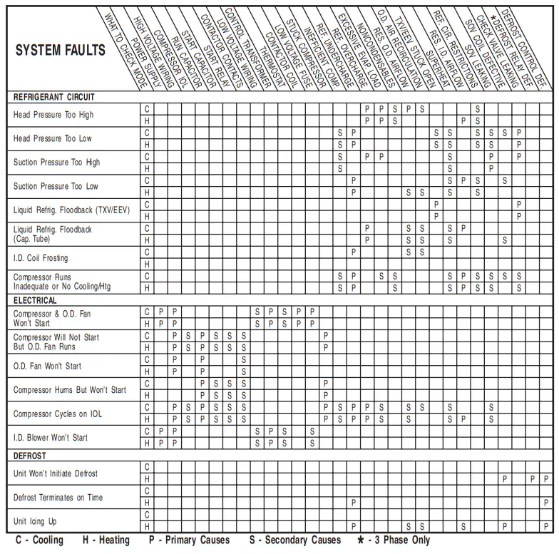
15.2 Troubleshooting
About American Standard Heating and Air Conditioning
American Standard has been creating comfortable and affordable living environments for more than a century. For more information, please visit www.americanstandardair.com.
The AHRI Certified mark indicates company participation in the AHRI Certification program. For verification of individual certified products, go to ahridirectory.org.
The manufacturer has a policy of continuous data improvement and it reserves the right to change design and specifications without notice. We are committed to using environmentally conscious print practices.
![]() © 2022 American Standard Heating and Air Conditioning
© 2022 American Standard Heating and Air Conditioning
11-BC39D1-1E-EN 13 Jun 2022
Supersedes 11-BC39D1-1D-EN (March 2020)


