SCREENLINE ECLIPSE Srl Instructions
INSTALLATION INSTRUCTION
Internal distance between brackets= viewing area + 2cm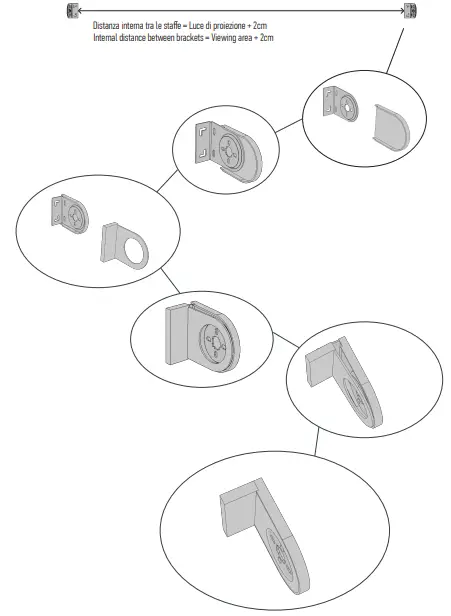
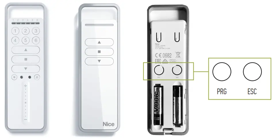
REMOTE CONTROLS SETTINGS
Primo setup
Initial setup
Perform the following operations on the shade to be configured and paired
 Unplug the power, wait 2 seconds and plug the power back in. Proceed to step 1 within 60 seconds.
In the case of a 6-channel remote control, select the desired channel using the buttons ranging from 1 to 6.
1  5 sec PRG
Press the PRG button for 5 seconds and release. The screen begins to perform up and down movements of random duration. At the beginning of the upward movement, press the upward key. The screen resumes its up and down movements of random duration. At the beginning of the downward movement, press the downward key. The movement stops and the screen performs 3 movements. Programming completed.
Push the PRG button for 5 seconds
Quick adjustment of thr limits switch (small millimetric variation
UPPER LIMIT SWITCH:
Go to the pre-set upper limit switch. Press the up or down button to obtain the desired position. Once obtained, hold down one of the keys for approximately 8 seconds. In response the shade will make 3 up and down movements Adjustment completed.
LOWER LIMIT SWITCH:
Go to the pre-set lower limit switch. Press the up or down button to obtain the desired position. Once obtained, hold down one of the keys for approximately 8 seconds. In response the shade will perform 3 up and down movements. Adjustment completed
End of stroke adjustment with remote control
LOWER LIMITS SWITCH:
![]() PRG
PRG![]() keep pressed for 5seconds
keep pressed for 5seconds with the arrows move to the desired position
![]() keep pressed for 5seconds 3 up and down movements to confirm successful adjustment
keep pressed for 5seconds 3 up and down movements to confirm successful adjustment
UPPER LIMIT SWITCH:
![]() PRG
PRG![]() keep pressed for 5secondswith the arfows moveto the desired position
keep pressed for 5secondswith the arfows moveto the desired position
keep pressed for 5seconds 3 up and down movements to successful adjustment
Thefollowing procedure is to be performed individually for each shade to be synchronised. It is used to set the stroke of the shades of 7-15-20- 30 seconds (stroke duration).
![]() PRG
PRG![]() PRG
PRG![]() keep pressed for 5seconds
keep pressed for 5seconds![]() press:
press:
1TIME =7 SECONDS
2TIMES =15 SECONDS
3TIMES =20 SECONDSA4
TIMES = 30 SECONDS![]() keep pressed for 5seconds 3 up and down movements to confirm successful adjustment
keep pressed for 5seconds 3 up and down movements to confirm successful adjustment
Connecting Instruction
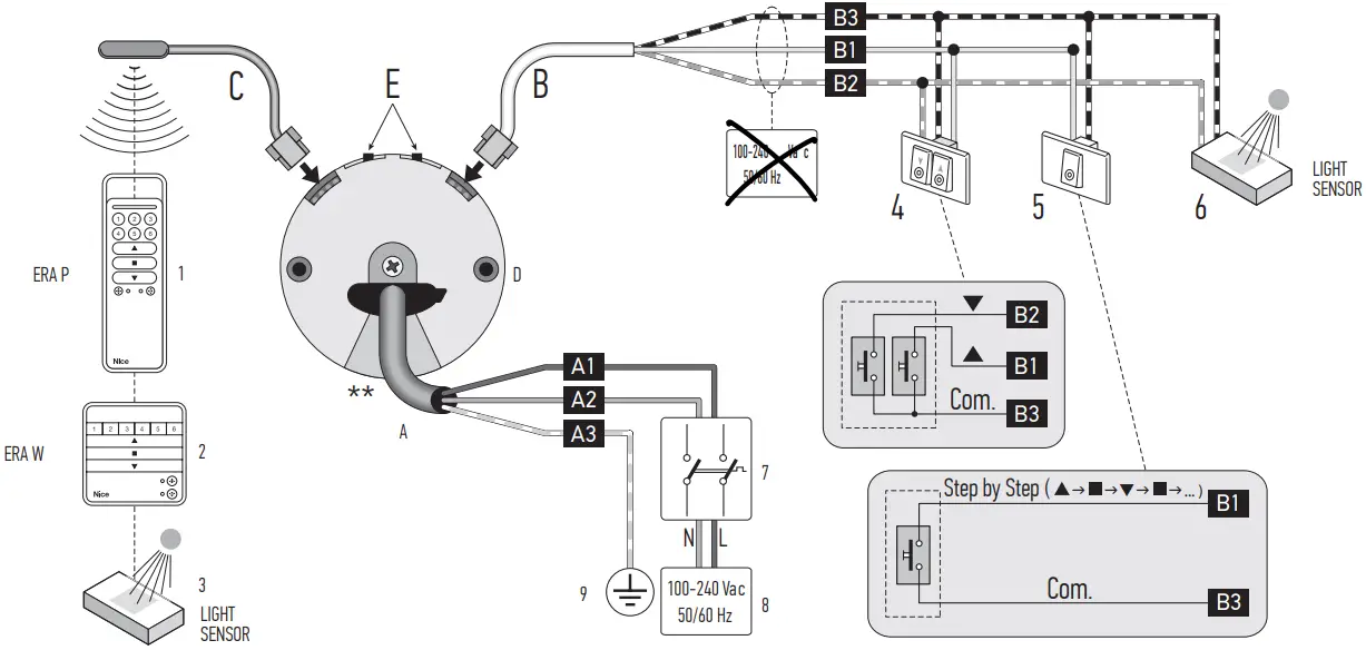
| A | EN USA (UL) | |
| A1 | White | |
| A2 | Black | |
| A3 | Green/ Yellow-green | |
DRY CONTACT
The power cable is removable
| LEGEND | |||
| A | Power cable | 1 | “ERA p. portable transmitter. |
| Al = Brown wire | 1 | ‘ERA W” portable transmitter | |
| A2 = Blue wire | 3 | Climate sensor (radio) | |
| A3 = Yellow-green wire | 4 | Double button | |
| B | Command cable | 5 | Single button (–Open’ or *Step-by-Step’ command) |
| 131 = White wire | 6 | Climate sensor (wired) | |
| B2 = White-orange wire | 7 | Motor mains power &connector | |
| B3 = White-black wire | 8 | Connection to the mains | |
| C | Aerial cable | 9 | Earth connection |
| D | Electronic motor head | ||
| E | Limit switch adjustment buttons | ||
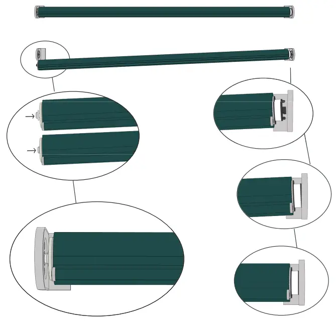
INSTALLATION OF THE MOTOR AND 2.2 – Assembling and installing the tubular motor
THE ACCESSORIES
Preliminary checks before installation and limitations on use
- Checkthe conditon oftheproduct right afer unpecking it
- Make sure that the torque,the rotaton speed and time o operaion o this motor are sitable for
automating your awning. In particular, do not install the motor i its torque is greater than that needed to move your awning. - To choose the right motor to the technical features of yaur awning refer to the the ‘Guide 2.3 – Installation of accessories 1o Selection” section, inthe “Nice Sreen” catelogue, — also avilable on wwnwiceforyoucom
- Check the dameter of the winding roller. This must be chosen according to the At installing the motor, installthe accessories, if required. I order to identify those motor torque, a follows thatare compatible and choose the models desired, see the “Nice Screen” catalogue,
- For motors fsize 5″ (035 ) theminimum nside ciamete of the winding whichis asoavalsble n wiwriceoryoucom Fig 2 shows the pe faccesories
roller must be 40 mm; thatare compatible and their connection to the motor (al of these are options - For motors ofsize M (8:= 45 mm) the minimum inide diameter of the winding and notincluded inthe package). rollr must be 52 mm;
- For motors fsize 5″ (035 ) theminimum nside ciamete of the winding whichis asoavalsble n wiwriceoryoucom Fig 2 shows the pe faccesories
- Additonal liitaions on use are lised in hapter 1 and i te technical characterstics onthe nameplate
Assembling and installing the tubular motor
Caution Read the safety Warning before proceeding incorrect installation could cause server physical injury.
To assembleandinstll the motor, efertofig. 3 he accessores shown nfig.3are notinclded i he package). To select the it switch gear wheel (i 3-), rve wheel (fg. 3-b), motor bracke (g 3- o to on use select supplementary cables (f diferent engths), efer to the “Nice Sreen” catalogue,which s lso available on wwwniceforyou.com
Installation of accessories
At installing the motor, installthe accessories, if required. I order to identify those motor torque, a follows thatare compatible and choose the models desired, see the “Nice Screen” catalogue, — For motors fsize 5″ (035 ) theminimum nside ciamete of the winding whichis asoavalsble n wiwriceoryoucom Fig 2 shows the pe faccesories roller must be 40 mm; thatare compatible and their connection to the motor (al of these are options — For motors ofsize M (8:= 45 mm) the minimum inide diameter of the winding and notincluded inthe package).
Costumer Support
38060 Besenello (TN) Via Nazionale, 1/n – 1/u |
+39 0464830003
[email protected]
screenline.it


