![]()
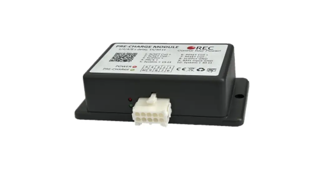
REC PRE-CHARGE UNIT V3.0
Features:
– robust and small design
– low power consumption @ 11-80 V DC
– 1/2/4/8 s DIP switch delay settings
– up to 120 V, 4.0 A pre-charge
– integrated 15 and 30 Ω power resistor + 10 Ω NTC
– 6.0 A top side coil drive with over-current protection
– single pole or bi-stable latching contactor drive
– reverse polarity protection
– over-voltage protection
– one-year warranty
General Description:
High input capacitance systems such as inverters, dc-dc converters, etc. can be exposed to large inrush currents during the initial power up procedure. If appropriate measures
are not employed, these currents can overly stress or even damage the system components. The pre-charge unit eliminates high in-rush currents by charging the input capacitor before the main contactor switches on, prolonging lifespan of the contactor and other components dramatically.
Parameters:
Table 1: Pre-charge parameter table.
| Parameter | Value | Unit |
| Supply voltage range Vcc — V55 | 10 – 80 | v |
| Supply current Ism | 1 @ VCC = 10 V | mA |
| 2 @VCC=30V | mA | |
| 3@VCC=60V | mA | |
| 4@VCC=80V | mA | |
| Battery pack voltage range VEAT – Vm | 10 – 120 V | V |
| BMS input voltage range | Vss — (Vss + 5.0) | V |
| BMS input voltage enable threshold | <=(Vss + 0.2) | Ω |
| BMS input voltage disable threshold | >(Vss + 1.7) | Ω |
| BMS input current | 0.03 | mA |
| Pre-charge resistance output pin 5 | 15 + NTC 10 | Ω |
| Pre-charge resistance output pin 10 | 30 + NTC 10 | Ω |
| Pre-charge output voltage VPRECHARGE | 30 + NTC 10 | Ω |
| Contactors + output coil voltage max | Vcc -0.7 | v |
| Contactors + output coil voltage min | Vcc -1.0 | v |
| Contactor coil fuse | 6.3 slow blow | A |
| Pre-charge fuse | 4.0 slow blow | A |
| Time delay | 1/2/4/8 | s |
| Bi-stable latching relay set/reset time | 100/150 | ms |
| Contactors — to VSS resistance | 100 | mΩ |
| Dimensions | 127x 70.6 x 35.5 | mm |
| Crimps | TE connectivity 795299-1 | n a |
| Crimping tool | 18-22 | AWG |
| Weight | 129 | g |
| IP rating | 20 | n a |
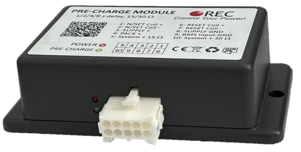
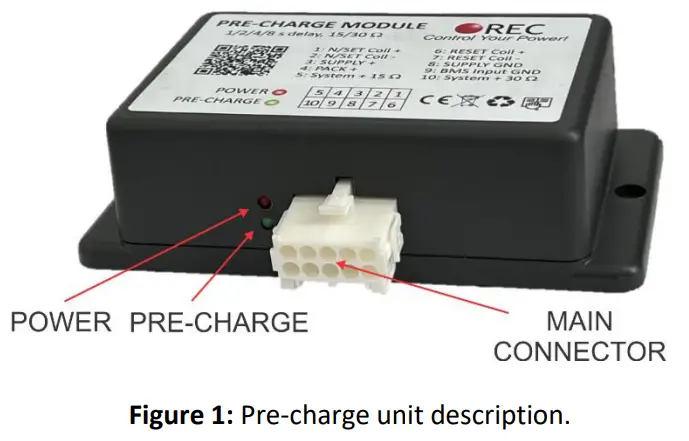
Pre-charge description:
Pre-charge connections:
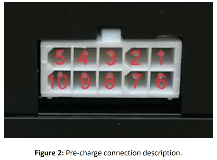
Table 2: Pre-charge pinout.
| Pin | Tab | Single pole contactor connection | 3i-stable latching contactor connection |
| 1 | N/SET COIL + | Contactor coil + | Bi-stable latching contactor SET coil + |
| 2 | N/SET COIL – | Contactor coil – | Bi-stable latching contactor SET coil – |
| 3 | SUPPLY + | Supply positive 10 — 80 V | Supply positive 10 — 80 V |
| 4 | PACK + | Battery pack + (10 — 120 V) | Battery pack + (10 — 120 V) |
| 5 | SYSTEM + 15 Ω | System side + pre-charge 15Ω | System side + pre-charge 15 Ω |
| 6 | RESET COIL + | – | Bi-stable latching contactor RESET coil + |
| 7 | RESET COIL – | – | Bi-stable latching contactor RESET coil – |
| 8 | SUPPLY GND | Supply GND | Supply GND |
| 9 | BMS Input GND | BMS input — pull down to Supply GND | BMS input — pull down to Supply GND |
| 10 | SYSTEM + 30 0 | System side + pre-charge 30 0 | System side + pre-charge 30 0 |
System Overview:
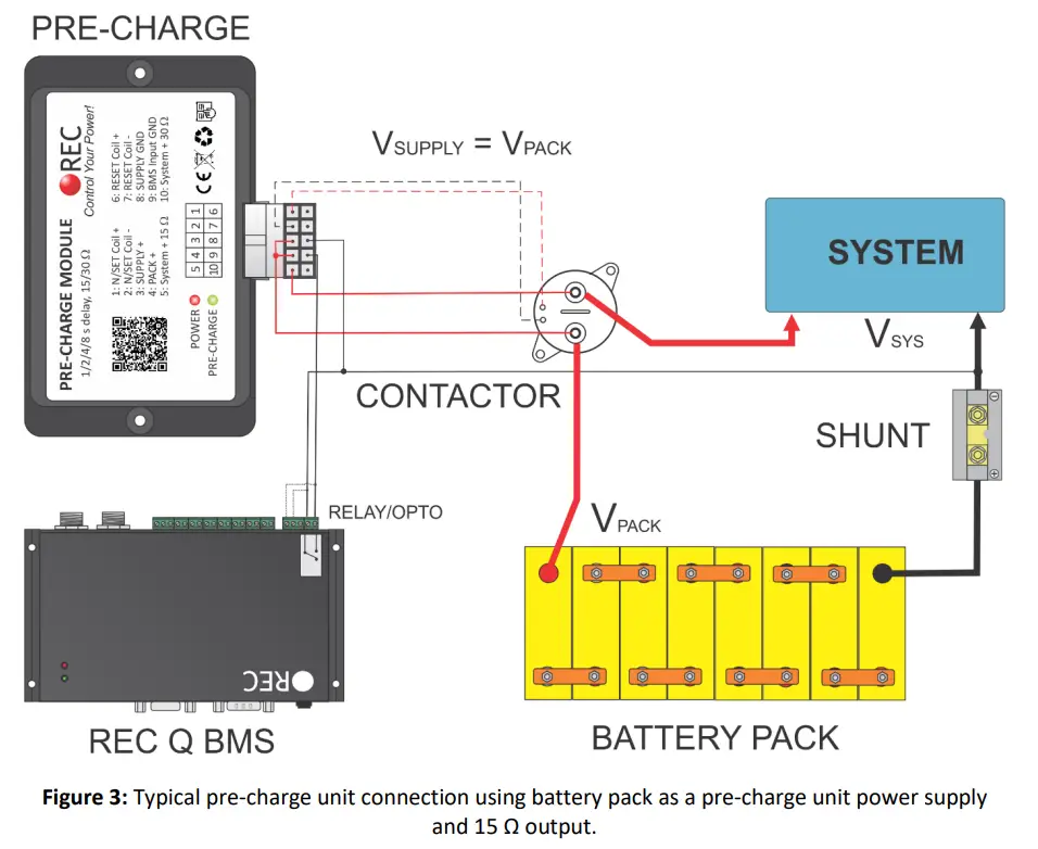
Figure 3 shows the integration of the pre-charge unit in a typical 24 V battery power system, using REC 1Q BMS with an internal relay control. Only the connections relevant to the pre-charge unit operation are shown. 15 Ω pre-charge output is used in conjunction with 24 V single coil power contactor. After the battery pack is connected to SUPPLY + and SUPPLY GND internal pre-charge slowly charges the input capacitor and powers the POWER red LED. Unit enters standby mode lowering its consumption
until the BMS input GND is pulled down to SUPPLY GND. Then the internal DIP switches are read (see Table 4 for detail settings description). When the pre-charge timeouts, SET coil is powered either constantly ON for normal single coil relay/contactor or turned ON for a period of 100 ms for engaging bi-stable latching relay. Then the pre-charge transistor inside the unit is turned OFF. When the BMS input GND is released, SET coil is either turned OFF or RESET output is powered for 150 ms to turn the bi-stable relay/contactor OFF.
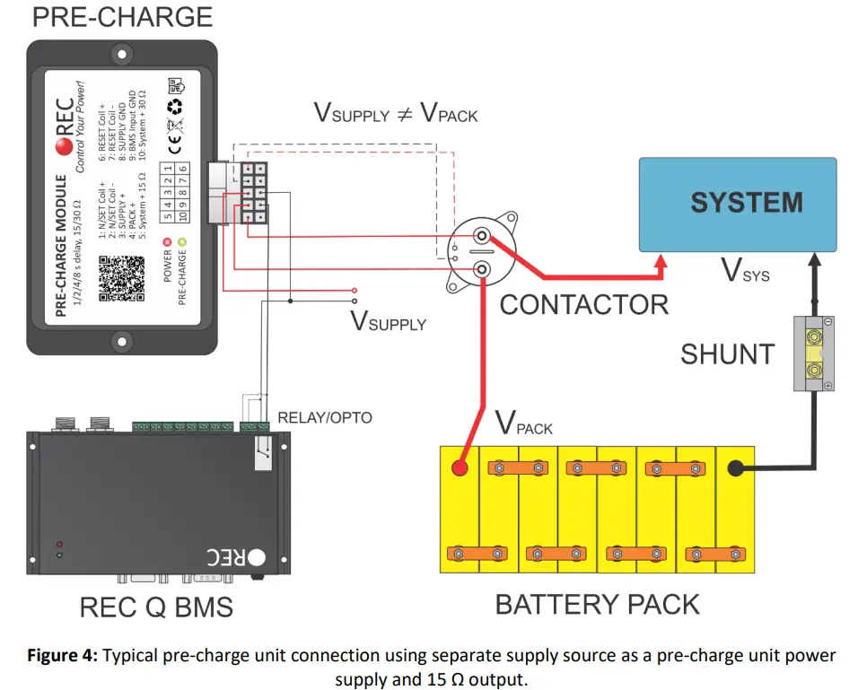
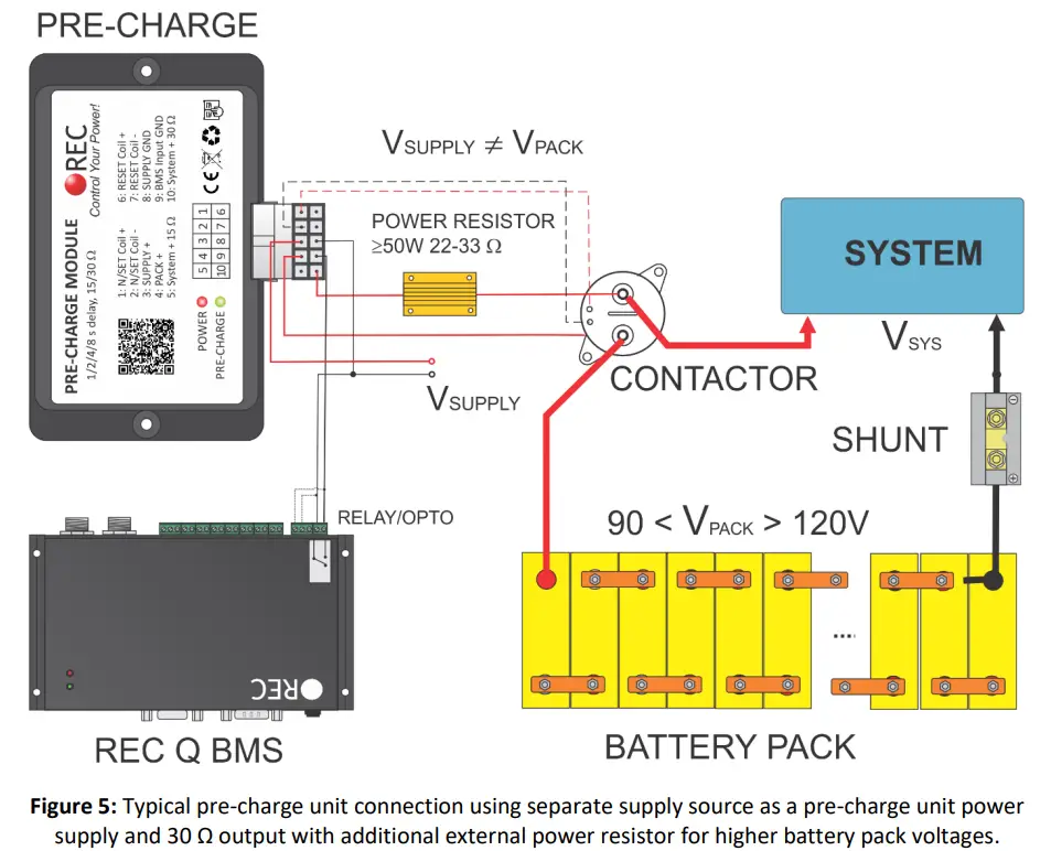
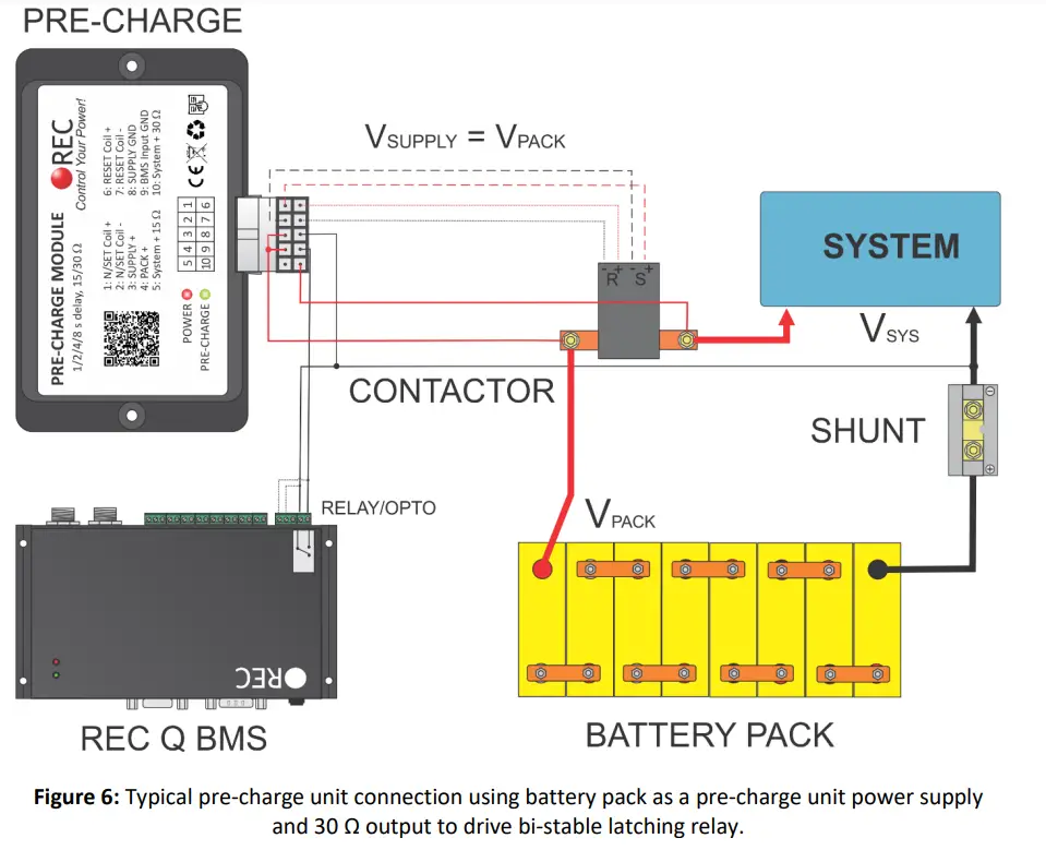
Figures 3 – 6 show typical system integrations.
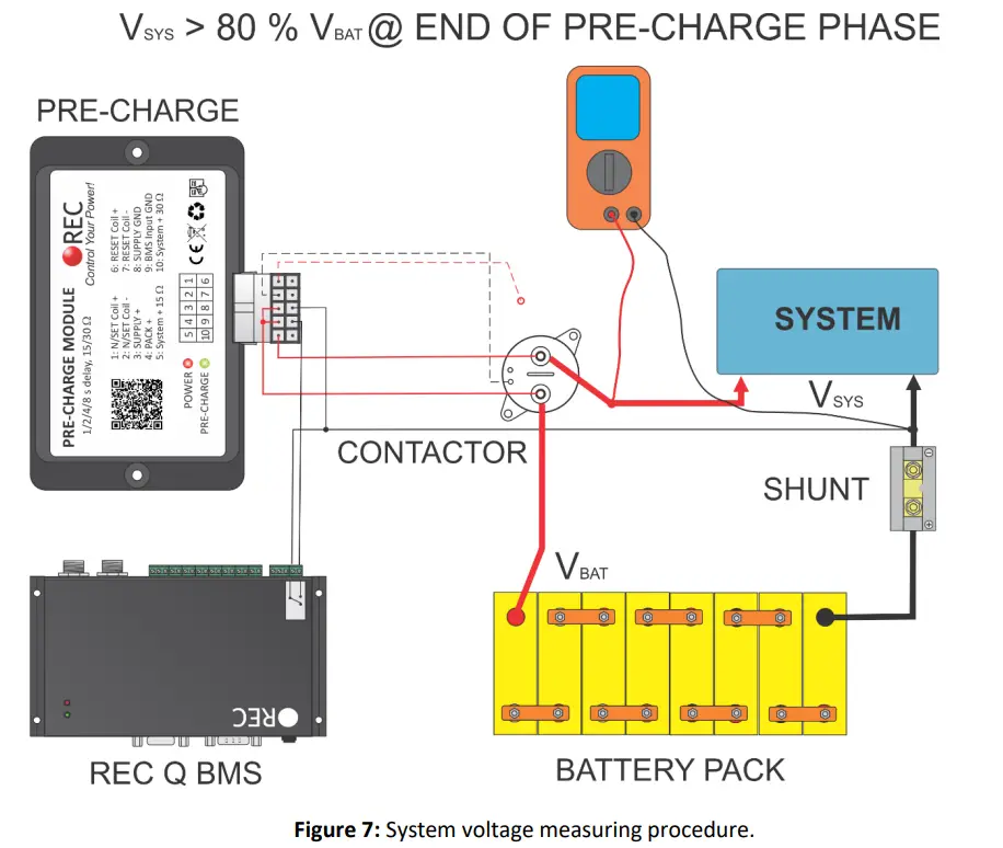
Measuring/Setting Pre-charge Delay:
To set the pre-charge delay properly, system voltage should be measured at the end of pre-charge timer phase. Connect all required connections except the N/SET COIL + connection to disable contactor engaging. Enable the pre-charge by pulling BMS Input GND to SUPPLY GND by the BMS or manually. Measure the system voltage @ the system side of the contactor. Before the pre-charge timer ends the system, voltage should rise to at least to 80 % of the battery voltage. If the voltage stays below this value increase the pre-charge delay or use the SYSTEM + 15 Ω output. Pre-charge current should be limited to a maximum value of 4 A (Max battery voltage / pre-charge resistance).
Table 3: Pre-charge resistance selection.
| Battery voltage [V] | Battery voltage range[V] | Pre-charge output |
| 12 | 10 -16 | SYSTEM + 15 Ω output |
| 24 | 21- 30 | SYSTEM + 15 Ω output |
| 48 | 43 – 67 | SYSTEM + 15Ω output |
| 80 | 64 -88 | SYSTEM + 30 Ω output |
| 80+ | 90 to 120 | SYSTEM + 30 Ω output + external 22-33 Ω 50 W |
Please note: Some of the inverters/controllers on the system side may start to work with lower voltage and their power consumption prevent system voltage to rise.
You can prolong the pre-charge time by changing DIP switches inside the Pre-charge unit without Precharge unit power disconnection. Per-charge only requires to be disabled by the BMS input GND. Bellow you can find DIP switch settings description.
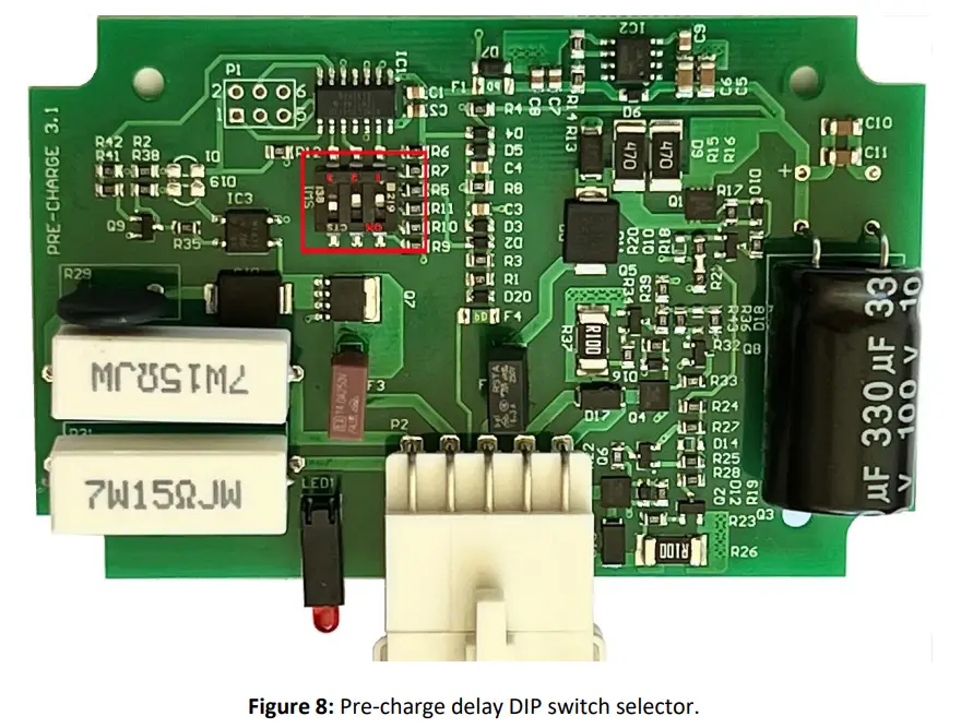
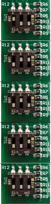
Table 3: DIP switch function description.
| Settings | DIP 3 | DIP 2 | DIP 1 | Function |
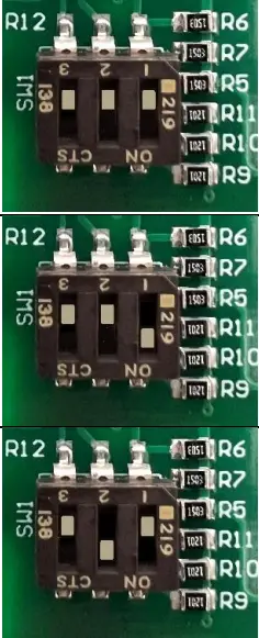 | OFF | OFF | OFF | Single pole contactor/relay 1 s pre-charge time |
| OFF | OFF | ON | Single pole contactor/relay 2 s pre-charge time | |
| OFF | ON | OFF | Single pole contactor/relay 4 s pre-charge time |
 | OFF | ON | ON | Single pole contactor/relay 8 s pre-charge time |
| ON | OFF | OFF | Bi-stable latching contactor/relay 1 s pre-charge time* | |
| ON | OFF | ON | Bi-stable latching contactor/relay 2 s pre-charge time | |
| ON | ON | OFF | Bi-stable latching contactor/relay 4 s pre-charge time | |
| ON | ON | ON | Bi-stable latching contactor/relay 8 s pre-charge time |
Dimensions:
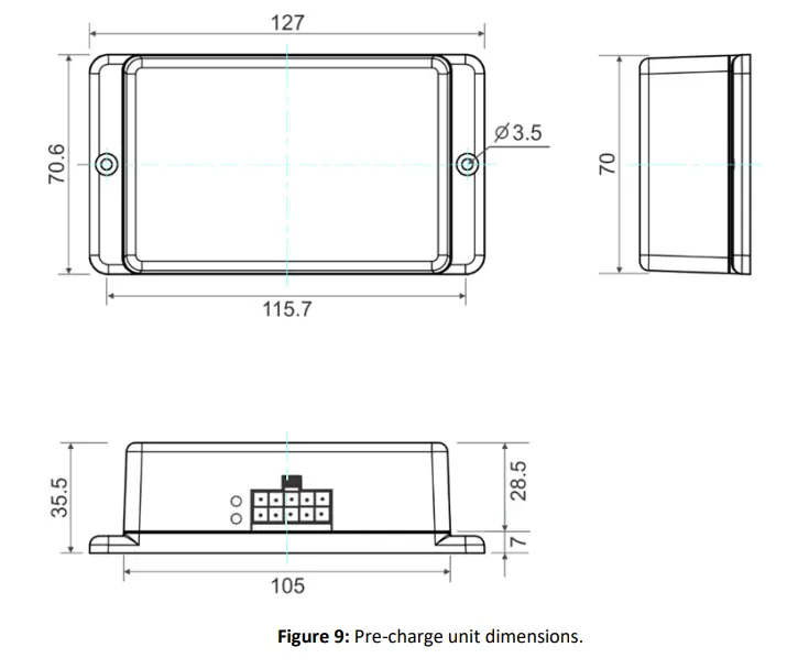
![]()
Rozna ulica 20, 6230 Postojna, Slovenia
mail: [email protected]; www.rec-bms.com


