![]()
ExTempMini Series
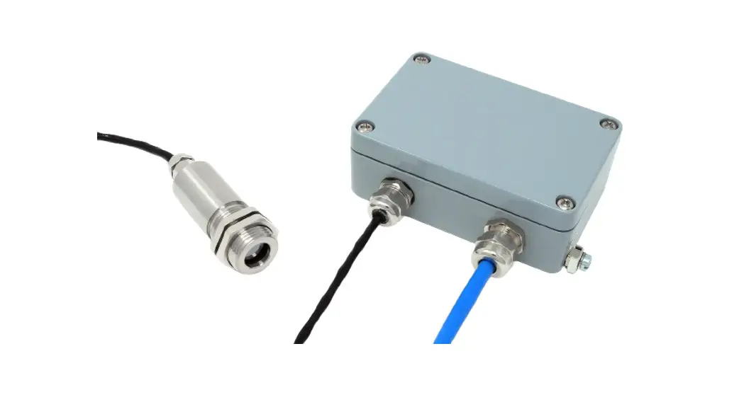
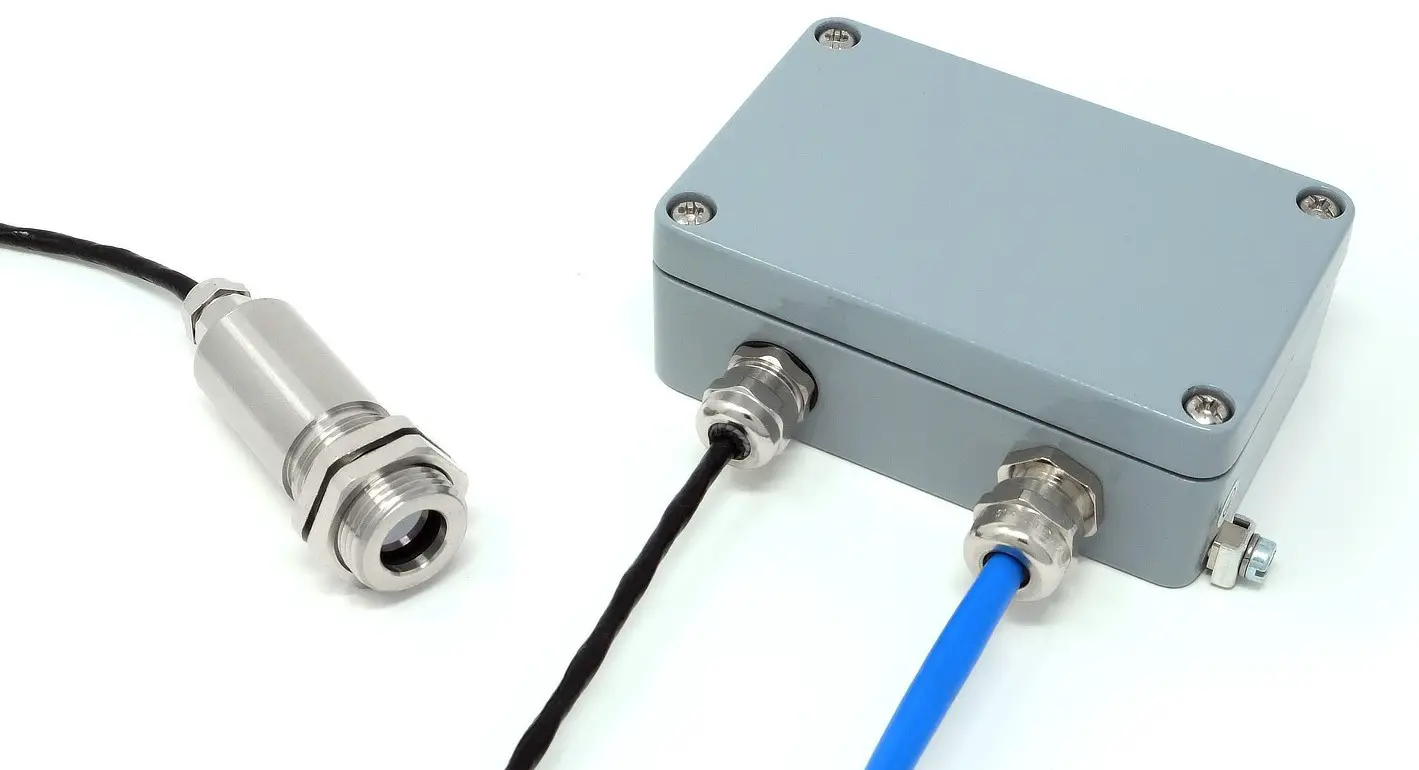
Intrinsically Safe Miniature
Infrared Temperature Sensor
with Separate Electronics Module
Operator’s Guide
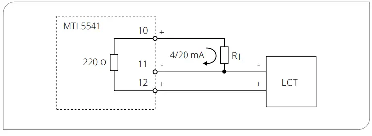
INTRODUCTION ExTempMini intrinsically safe non-contact infrared temperature sensors measure the temperature of an area of the surface of a solid or liquid, and transmit this as a linear 4-20 mA output. Voltage MUST be supplied by a suitably rated safety isolator. CONFORMANCE TO REQUIREMENTS SPECIFIC CONDITIONS OF USE CONDITIONS FOR SAFE USE (JAPAN) The device must not be used outside of the ambient temperature range (Ta), or subjected to voltages, current or power greater than those listed below, in order to ensure safe operation of the device: All models of the ExTempMini have been issued an ATEX (CML 22ATEX2007X) Certificate for use in gas explosive atmospheres in above ground installations. Table 1: Gas and Dust Zones in which the ExTempMini may or may not be used Table 2: Gas and Dust Groups in which the ExTempMini is suitable/unsuitable for use Table 3: Gas ignition temperature classifications to which the ExTempMini conforms / does not conform MODEL NUMBER Conforms to EN 61326-1, EN 61326-2-3 (Industrial). A range of accessories to suit different applications and industrial environments is available as follows. These may be ordered at any time and added on-site: The following options are available. Options are factory installed and must be ordered with the sensor. OPTICS The installation process consists of the following stages: Distance and Spot Size Ensure the sensor is positioned so that it can only detect infrared radiation from the target. Ambient Temperature Atmospheric Quality Electrical Interference Wiring Power Supply Mounting The lens must be kept clean and dry for an accurate reading. * Cable shield is terminated in main enclosure gland – see OUTPUT CABLE INSTALLATION The recommended output cable type is LAPP ÖLFLEX EB CY 2×0.75mm². An alternative cable may be used. See the ExTempMini Guide to Certification and Installation for full details. The main enclosure must be connected to earth using the provided earth terminal. The output cable shield must be terminated to the enclosure as per the above instructions, and the cable shield must not be connected to earth at the other end. A choice of two digital communication interfaces is available. All models are configurable via the optional USB adapter (Loop Configuration Tool, model LCT) and free CalexConfig configuration software. The optional LCT-485 Network Interface (not shown) allows an ExTemp sensor to be connected to an RS-485 Modbus RTU network for temperature measurement, configuration and data acquisition. The following settings can be configured via CalexConfig. Temperature Units Output Range Output Processing Emissivity and Compensation Once the sensor is in position, a suitable safety isolator is connected and configured, and the appropriate power and cable connections are secure, the system is ready for continuous operation by completing the following simple steps: Be aware of the following when using the sensor: Our customer service representatives are available for application assistance, calibration, repair, and solutions to specific problems. Contact our Service Department before returning any equipment. In many cases, problems can be solved over the telephone. If the sensor is not performing as it should, try to match the symptom below to the problem. If the table does not help, contact us for further advice. Keep the lens clean and dry at all times. Any foreign matter on the lens would affect measurement accuracy. Blow off loose particles (if not using the air purge accessory) with an air ‘puffer’. Connect the device to the 4 to 20 mA measurement loop via the hook-type connectors. For reliable communications, the total resistance RL on the 4 to 20 mA loop should be within the range specified on the connection diagrams. You may need to connect a resistor in series with the existing measurement instrumentation on the 4 to 20 mA loop to ensure this. The LCT connectors are colour coded as follows: This isolator has an internal resistance of 220Ω. Two wiring configurations are possible, depending on whether or not this internal resistance is used. Configuration B: 180 Ω ≤ RL ≤ 580 Ω (using the internal resistance) The latest version of the software is available for download from the Calex website at the following URL: www.calex.co.uk/software USING THE SOFTWARE Our technical support engineers are available for application assistance, calibration, repair, and solutions to specific problems. Contact our Service Department before returning any equipment. In many cases, problems can be solved over the telephone. Contact us for further advice. Calex guarantees each instrument it manufactures to be free from defect in material and workmanship under normal use and service for the period of two years from the date of purchase. This guarantee extends only to the original buyer according to the Calex Terms and Conditions of Sale. Calex Electronics Limited Issue C – Feb 2022
Temperature ranges from -20°C to 1000°C are available. All models have an adjustable emissivity setting, and may be used to measure a wide variety of target materials, including food, paper, textiles, plastics, leather, tobacco, pharmaceuticals, chemicals, rubber, coal, asphalt and paint.
A choice of optics is available to measure small or large targets at short or long distances.
The optional LCT Loop Configuration Tools (USB and RS-485 adapters) and free software allow the ExTempMini to be connected to a PC, PLC or SCADA system for temperature indication, sensor configuration and data acquisition.
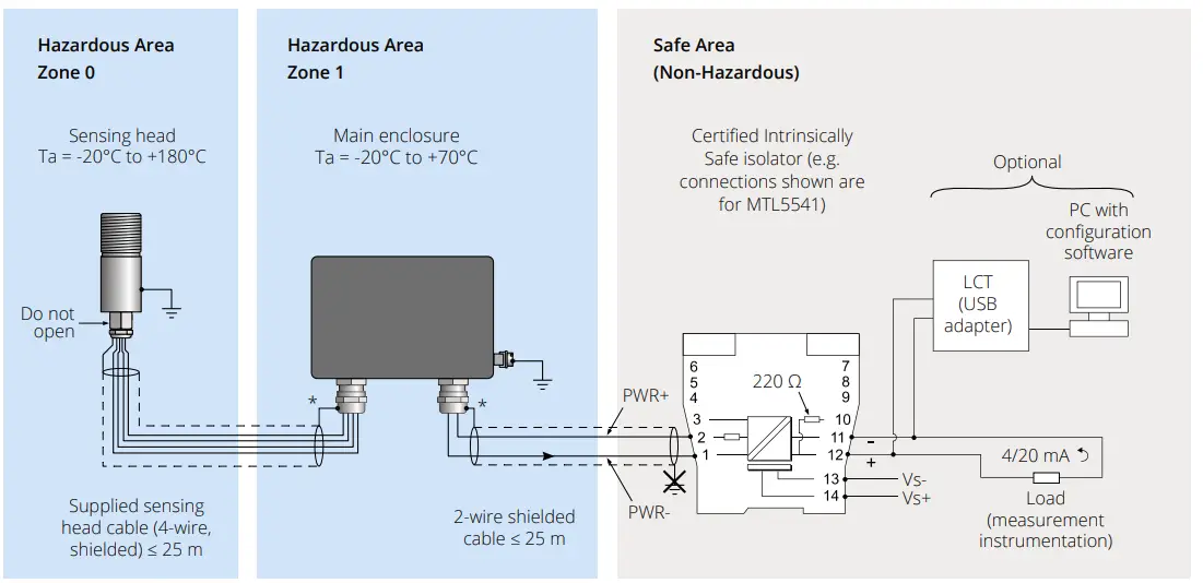
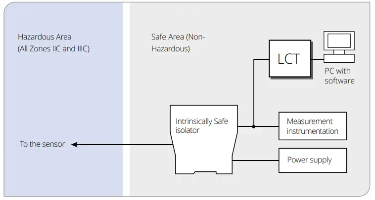
These sensors are designed primarily for use in hazardous areas in conjunction with a suitable Intrinsically Safe isolator. All models have been certified Intrinsically Safe for use in gas hazardous areas by Certification Management Ltd. They comply with the European ATEX Directive 2014/34/EU and are covered by certificates for IECEx (international) and UKCA (United Kingdom). The ExTempMini Series is also approved for use in Japan (JNIOSH-TR-46-1:2020 (General requirements); JNIOSH-TR-46-6:2015 (Intrinsic Safety “i”)).![]() IMPORTANT INFORMATION FOR USE:
IMPORTANT INFORMATION FOR USE:
For re-configuration of the sensor, the LCT MUST be connected in the safe area, behind the protection of a safety isolator.
The sensing head MUST NOT be opened. Care should be taken to avoid inadvertently loosening the cable gland when tightening locknuts.
Do not attempt to repair a faulty unit. Contact the vendor to arrange a return.
The sensing head has passed a high voltage withstand test up to 700 VDC.
The main enclosure of this equipment is not capable of withstanding the 500 VAC / 700 VDC insulation test required by IEC 60079-11:2011 Clause 6.3.13. This shall be taken into account when installing the equipment. Power to the equipment must be supplied by an intrinsically safe isolator. The equipment is not compatible with intrinsically safe Zener barriers.SAFETY PARAMETERS:
Ui = 28 V Ta = -20°C to +70°C (Main Enclosure)
-20°C to +180°C (Sensing Head) (see Hazardous Area Classification)Ii = 93 mA Ci = 5.17 nF Pi = 0.651 W Li = 1.99 µH INTRINSIC SAFETY CERTIFICATION
The sensing head can be used in all gas Zones including Zone 0. The main enclosure can be installed in Zone 1. The sensing head temperature classification is T3 for ambient temperatures above 115°C.
Tables 1-3 describe the ATEX Gas Groups, Gas Zones, and gas ignition temperature classifications in which the ExTempMini is suitable:Zone Description Supported? Gas 0 Explosive gas air mixture continuously present. ✓ 1 Explosive gas air mixture likely to occur in normal operation. ✓ 2 Explosive gas air mixture not likely to occur, and if it does it will only exist for a short time. ✓ Dust 20 Explosive atmosphere in the form of a cloud of combustible dust in air is continuously present, or for long periods or frequently. NO 21 Explosive atmosphere in the form of a cloud of combustible dust in air is likely to occur occasionally in normal operation. NO 22 Explosive atmosphere in the form of a cloud of combustible dust in air is not likely to occur in normal operation, but if it does occur, will only persist for a short period. NO Group Definition Supported? Gas IIA e.g. Propane ✓ IIB e.g. Ethylene ✓ IIC e.g. Hydrogen ✓ Dust IIIA Combustible flyings NO IIIB Non-conductive dusts NO IIIC Conductive dusts NO Gas Ignition
TemperatureClassification Supported? Main Enclosure Sensing Head
-20°C ≤ Ta ≤ 115°CSensing Head
-20°C ≤ Ta ≤ 180°C450 °C T1 ✓ ✓ ✓ 300 °C T2 ✓ ✓ ✓ 200 °C T3 ✓ ✓ ✓ 135 °C T4 ✓ ✓ NO 100 °C T5 NO NO NO 85 °C T6 NO NO NO 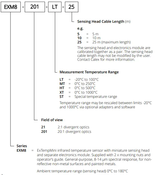
SPECIFICATIONS
General Temperature Range -20°C to 1000°C (see table of Model Numbers) Output 4 to 20 mA Minimum Temperature Span 100°C Maximum Temperature Span 1000°C Field of View See table of Model Numbers Accuracy ± 1°C or 1% of reading, whichever is greater Repeatability ± 0.5°C or 0.5%, whichever is greater Emissivity Setting Range 0.20 to 1.00 (pre-set to 0.95) Emissivity Setting Method User configurable via optional USB / RS-485 adapters Response Time, t90 240 ms (90% response) Spectral Range 8 to 14 μm Supply Voltage 12 to 24 V DC ± 5% Minimum Sensor Voltage 11.4 V DC Maximum Current Draw 25 mA Mechanical Main Enclosure Sensing Head Construction Painted aluminium Stainless Steel 316 Major Dimensions 99 x 65 x 35 mm Ø 20 x length 68.5 mm including cable gland (see Dimensions) Mounting 2 x mounting holes, use M4 socket head screws M20 x 1.5 mm thread, length 20 mm, supplied with two mounting nuts Cable Length (Sensing Head) – Choice of 5 m, 10 m or 25 m factory- fitted. Contact Calex for information about extending cable. Weight with 5 m Cable TBD TBD Cable Connections Removable screw terminal blocks (see Connections). Conductor size 22 AWG to 14 AWG (0.326 mm² to 2.08 mm²) – Output Cable Gland Suitable for cable diameters 3.5 to 7.0 mm – Environmental Main Enclosure Sensing Head Environmental Rating IP65 (NEMA 4) IP65 (NEMA 4) Ambient (Operating) Temperature Range 0°C to 70°C 0°C to 180°C Ambient Pressure Range 80 kPa (0.8 bar) to 110 kPa (1.1 bar) 80 kPa (0.8 bar) to 110 kPa (1.1 bar) Relative Humidity Max. 95% non- condensing Max. 95% non-condensing CE Marked Yes Yes RoHS Compliant Yes Yes Hazardous Area Classification Main Enclosure Sensing Head Ambient Temperature Rating -20°C ≤ Ta ≤ 70°C -20°C ≤ Ta ≤ 115°C -20°C ≤ Ta ≤ 180°C ATEX Classification Ex II 2 G Ex II 1 G Ex II 1 G IECEx Classification (Gas) Ex ia [ia Ga] IIC T4 Gb Ex ia IIC T4 Ga Ex ia IIC T3 Ga Maximum DC Input Voltage Ui = 28 V Maximum Input Current Ii = 93 mA Maximum Input Power Pi = 0.651 W Maximum Internal Capacitance Ci = 5.17 nF Maximum Internal Inductance Li = 1.99 µH ATEX Certificate Number CML 22ATEX2007X IECEx Certificate Number IECEx CML 22.0001X JapanEx Certificate Number CML 22JPN2009X UKCA Certificate Number CML 22UKEX2008X ELECTROMAGNETIC COMPATIBILITY
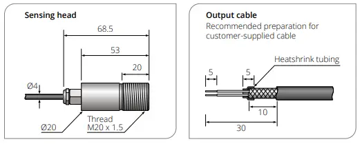
DIMENSIONS (all dimensions in mm)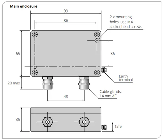
ACCESSORIES
OPTIONS
The below chart shows the measured spot diameter at the given distances from the sensing head and assumes 90% energy. The sensor may be used at longer distances than shown below, with a larger measured spot size.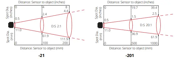
INSTALLATION AND MAINTENANCE
Please read the following sections thoroughly before proceeding with the installation.PREPARATION
The size of the area (spot size) to be measured determines the distance between the sensor and the target.
The spot size must not be larger than the target.
The sensor should be mounted so that the measured spot size is smaller than the target.
We normally recommend the target is at least twice the size of the given measured spot for maximum accuracy.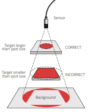
The sensing head is designed to operate in ambient temperatures from 0°C to 180°C.
The main enclosure is designed to operate in ambient temperatures from 0°C to 70°C.
Avoid thermal shock. Allow 20 minutes for the unit to adjust to large changes in ambient temperature.
Smoke, fumes or dust can contaminate the lens and cause errors in temperature measurement. In these types of environment the air purge collar should be used to help keep the lens clean.
To minimise electromagnetic interference or ‘noise’, the sensor should be mounted away from motors, generators and such like.
Check the distance between the sensor and the indicating/controlling device. If necessary, the sensor can be ordered with a longer cable attached. Contact Calex for information about extending the cable.
A suitable intrinsically safe isolator must be used. See Specifications for the supply voltage, current and safety requirements.MECHANICAL INSTALLATION
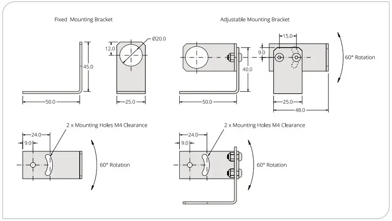
The sensing head is supplied with 2 mounting nuts. The sensor can be mounted on brackets or cut outs of your own design, or you can use the fixed and adjustable mounting bracket accessories, which are shown in the following diagram.MOUNTING BRACKETS
AIR PURGE COLLAR
The optional air purge collar is used to keep dust, fumes, moisture, and other contaminants away from the lens. It must be screwed on fully.
There are two models of air purge collar to suit the different optics (see below).
Air flows into the hose barb fitting and out of the front aperture. Air flow should be no more than 5 to 15 litres/min. Clean or ‘instrument’ air is recommended.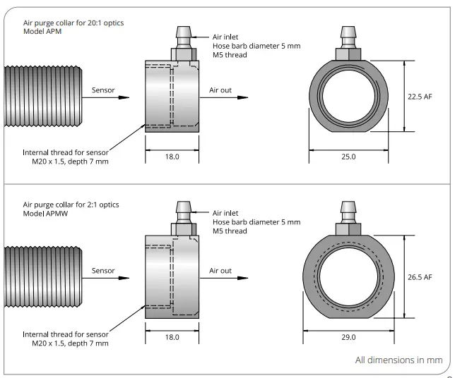
ELECTRICAL INSTALLATION
OUTPUT CABLE INSTALLATION
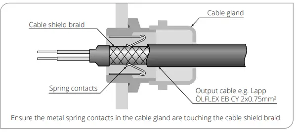
GROUNDING
DIGITAL COMMUNICATION AND CONFIGURATION
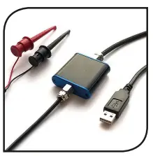
For temporary connection, configuration of the sensor, and diagnostics, we suggest the USB adapter, model LCT.
For continuous digital communications, configuration and data acquisition, we suggest the RS-485 Modbus network interface, model LCT-485.![]() The LCT and LCT-485 are not certified for use in hazardous areas. They must only be connected on the safe side of the safety isolator.
The LCT and LCT-485 are not certified for use in hazardous areas. They must only be connected on the safe side of the safety isolator.USB
The LCT has hook-type connectors and may be connected to the 4-20 mA loop as shown above.
For information about installing and using the LCT, see the Loop Configuration Tool (LCT) section of this manual.RS-485 MODBUS
Each LCT-485 unit provides connectivity for one sensor, and multiple LCT-485 units can be connected to a single Modbus network.
See the ExTemp data sheet and LCT-485 Operator’s Guide for more information.CONFIGURABLE PARAMETERS
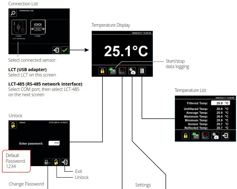
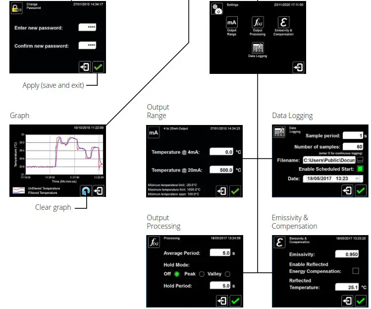
Configuration settings are password protected. To access the Settings menu, go to the Unlock screen and enter the password. The default password is 1234.
On the temperature display screen, click °C or °F to switch between temperature units.
Go to the Settings screen, then Output Range.
Set the temperature range limits for the 4 to 20 mA output, between the limits of -20°C and 1000°C.
The difference between the temperatures at 4 mA and at 20 mA must be at least 100°C. The temperature at 20 mA must be greater than the temperature at 4 mA. Default setting: Depends on model, e.g. LT = -20°C to 100°C (see Model Numbers)
Go to the Settings screen, then Output Processing.
Set the time, in seconds, over which the measured temperature is averaged.
Note: averaging prevents the sensor from following rapid temperature changes. Default setting: 0
If required, hold processing can be applied by setting Hold Mode to “Peak” or “Valley” and setting the hold period. This is useful if the temperature reading is interrupted by gaps between moving objects, or by an obstruction.
Default setting : OFF
Go to the Settings screen, then Emissivity and Compensation.
Enter the emissivity of the target. Target emissivity can be determined experimentally, or estimated using an emissivity table. For more information, contact Calex. Default setting: 0.95
If enabled, compensates for errors caused by reflected energy from hotter or colder objects. This should generally be kept OFF in most applications.Default setting: OFF
Enter the temperature of the surroundings of the target for Reflected Energy Compensation. Changing this has no effect if Reflected Energy Compensation is OFF.OPERATION
IMPORTANT
MAINTENANCE
LENS CLEANING
If dust or condensation continuously forms on the lens, consider fitting an air purge collar.TROUBLESHOOTING
Symptom Probable Cause Solution No output No power to sensor Check power supply and wiring Inaccurate measured temperature Target too small for sensor’s field of view Ensure the sensor’s view is completely filled by the target. Position the sensor closer to the target to measure a smaller area.Ensure the target is at least twice the size of the given measured spot. Target is a reflective metal surface Measure a non-reflective area, or paint or coat a measurable area of the target to make it non-reflective Field of view obstruction Remove obstruction; ensure sensor has a clear view of target Dust or condensation on lens Ensure lens is clean and dry. Clean gently with a soft lens cloth and water. If problem recurs, consider using an air purge collar. Incorrect wire connections Check wiring against markings on PCB at terminal blocks Output temperature scale mismatch Re-scale input temperature range on measurement instrument to match sensor LOOP CONFIGURATION TOOL (LCT)
![]() WARNING
WARNING
This device MUST NOT be used in hazardous areas. It is not certified for use in explosive atmospheres and may only be connected on the safe side of a suitable, certified Intrinsically Safe isolator. Do not attempt to repair a faulty unit. Contact the vendor to arrange a return.ELECTRICAL CONNECTION
WIRE IDENTIFICATION – LCT
Colour of Wire and Hook Connector Polarity Red + Black – EXAMPLE ISOLATOR: MODEL MTL5541
Configuration A: 400 Ω ≤ RL ≤ 800 Ω (not using the internal resistance)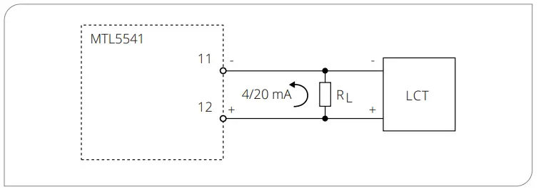
SOFTWARE
Install the software before connecting the LCT to a Windows PC. This will ensure the driver is properly installed.
See Configurable Parameters and the Configuration Software diagram opposite.
If the Settings icon is greyed out, the software is locked. Unlock the software to allow access to the Settings menu. The default password is 1234.MAINTENANCE AND TROUBLESHOOTING
GUARANTEE
CONFIGURATION SOFTWARE
PO Box 2, Leighton Buzzard, Bedfordshire, England LU7 4AZ
Tel: +44 (0)1525 373178 [email protected] www.calex.co.uk


 Thermometer User Manual")


