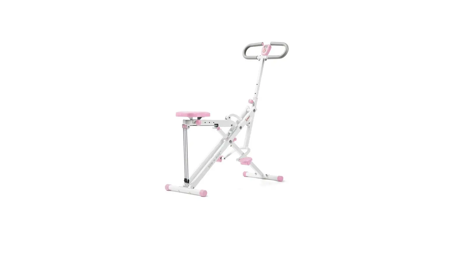
Sunny Health Fitness P2100 Upright Row-N-Ride™ Exerciser In Pink User Manual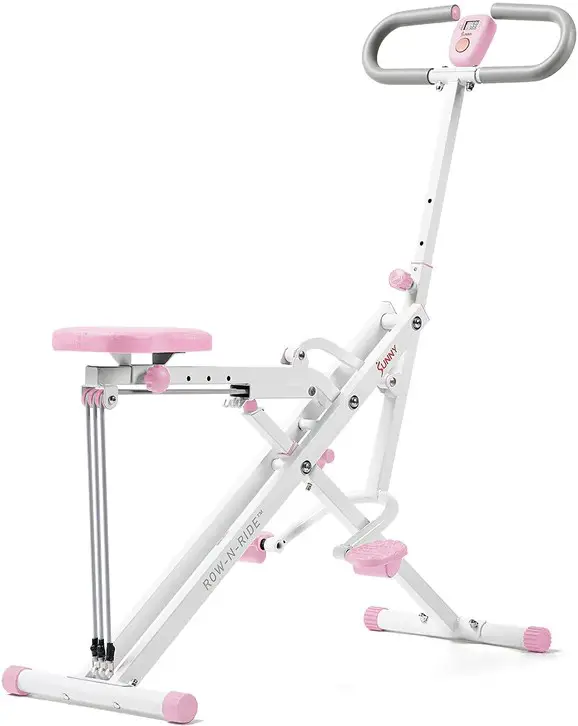
IMPORTANT! Please retain owner’s manual for maintenance and adjustment instructions. Your satisfaction is very important to us, PLEASE DO NOT RETURN UNTIL YOU HAVE CONTACTED US: [email protected] or 1-877-90SUNNY (877-907-8669).
IMPORTANT SAFETY INFORMATION
We thank you for choosing our product. To ensure your safety and health, please use this equipment correctly. It is important to read this entire manual before assembling and using the equipment. Safe and effective use can only be achieved if the equipment is assembled, maintained, and used properly. It is your responsibility to ensure that all users of the equipment are informed of all warnings and precautions.
- Before starting any exercise program, you should consult your physician to determine if you have any medical or physical conditions that could put your health and safety at risk or prevent you from using the equipment properly. Your physician’s advice is essential if you are taking medication that affects your heart rate, blood pressure, or cholesterol level.
- Be aware of your body’s signals. Incorrect or excessive exercise can damage your health. Stop exercising if you experience any of the following symptoms: pain, tightness in your chest, irregular heartbeat, shortness of breath, lightheadedness, dizziness, or feelings of nausea. If you do experience any of these conditions, you should consult your physician before continuing with your exercise program.
- Keep children and pets away from the equipment. The equipment is designed for adult use only.
- Use the equipment on a solid, flat level surface with a protective cover for your floor or carpet. To ensure safety, the equipment should have at least 2 feet (60 CM) of free space all around it.
- Ensure that all nuts and bolts are securely tightened before using the equipment. The safety of the equipment can only be maintained if it is regularly examined for damage and/or wear and tear.
- Always use the equipment as indicated. If you find any defective components while assembling or checking the equipment, or if you hear any unusual noises coming from the equipment during exercise, discontinue use of the equipment immediately and do not use until the problem has been rectified.
- Wear suitable clothing while using the equipment. Avoid wearing loose clothing that may become entangled in the equipment.
- Do not place fingers or objects into the moving parts of the equipment.
- The maximum weight capacity of this unit is 220 pounds (100KG).
- This equipment is not suitable for therapeutic use.
- To avoid bodily injury and/or damage to the product or property, proper lifting and moving are required.
- Your product is intended for use in cool and dry conditions. You should avoid storage in extreme cold, hot or damp areas as this may lead to corrosion and other related problems.
- This equipment is designed for indoor and home use only; it is not intended for commercial use.
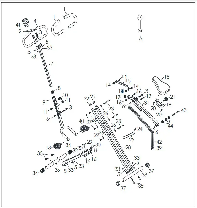
EXPLODED DIAGRAM
HARDWARE PACKAGE
PARTS LIST
| No. | Description | Spec. | Qty. |
| 1 | Sponge | 2 | |
| 2 | Plug | Ø25*1.5 | 2 |
| 3 | Bolt | M8*42 | 4 |
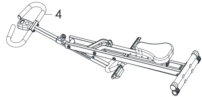
| 4 | Handlebar | 1 | |
| 5 | Washer | OD22*ID8 | 6 |
| 6 | Nut | M8*13 | 3 |
| 7 | Handlebar Tube | 1 | |
| 8 | Bushing | 2 | |
| 9 | Pedal Connecting Tube | 1 | |
| 10 | Knob | Ø38*L65*M16 | 1 |
| 11 | Bearing Sleeve | 2 | |
| 12 | Hexagon Screw | M8*50 | 1 |
| 13 | Pedal (L) | 1 | |
| 14 | Bearing Sleeve | 4 | |
| 15 | Connecting Tube | 1 | |
| 16 | Bearing Sleeve | 4 | |
| 17 | Plug | 30*30*1.5 | 1 |
| 18 | Seat | 1 | |
| 19 | Fixed Iron Sheet | 1 | |
| 20 | Screw | M6 | 2 |
| 21 | Knob | Ø47*40*M8 | 1 |
| 22 | Plug | 40*20*1.5 | 2 |
| 23 | Bolt | M10 | 3 |
| 24 | Stopper | 1 | |
| 25 | Seat Tube | 1 | |
| 26 | Washer | OD20*ID11 | 6 |
| 27 | Nut | M10 | 3 |
| 28 | Main Frame | 1 | |
| 29 | Pin | 1 | |
| 30 | Plug | Ø19*35 | 2 |
| 31 | Seat Connecting Tube | 1 | |
| 32 | Front Connecting Tube | 1 | |
| 33 | Nut | M8*12 | 6 |
| 34 | Cap | 2 | |
| 35 | Bolt | M8*48 | 4 |
| 36 | Front Stabilizer | 1 | |
| 37 | End Cap | 2 | |
| 38 | Rear Stabilizer | 1 | |
| 39 | Square Buckle | 3 | |
| 40 | Pedal (R) | 1 | |
| 41 | Meter | 1 | |
| 42 | Exercise Band | 3 | |
| 43 | Bolt | M8*65 | 1 |
| 44 | Plastic Wheel | 3 | |
| A | Spanner | 1 |
Ordering Replacement Parts (U.S. and Canadian Customers only
Please provide the following information in order for us to accurately identify the part(s) needed:
- The model number (found on cover of manual)
- The product name (found on cover of manual)
- The part number found on the “EXPLODED DIAGRAM” and “PARTS LIST” (found near the front of the manual)
Please contact us at [email protected] or 1-877-90SUNNY (877-907-8669).
ASSEMBLY INSTRUCTIONS
We value your experience using Sunny Health and Fitness products. For assistance with parts or
troubleshooting, please contact us at [email protected] or 1-877 90SUNNY (877- 907-8669)
STEP 1:
Open the Main Frame (No. 28) as shown in the picture on the left.
NOTE: The Pin (No. 29) has been inserted into Front Connecting Tube (No. 32).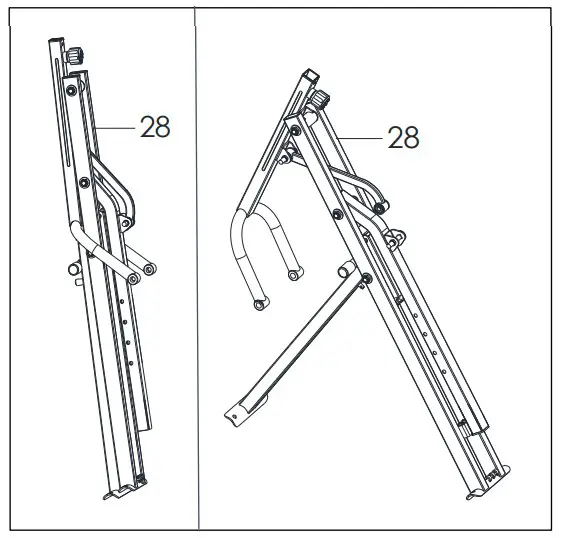
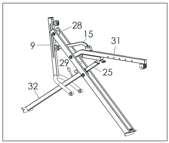
STEP 2:
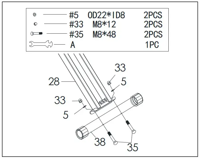
Remove 4 Bolts (No. 35), 4 Nuts (No. 33) and 4 Washers (No. 5) from the Front and Rear Stabilizers (No. 36 & No. 38) with Spanner (No. A). Attach FrontStabilizer (No. 36) to Front Connecting Tube (No. 32) using 2 Bolts (No. 35), 2 Nuts (No 33) and 2 Washers (No. 5) that were removed. Tighten and secure with Spanner (No. A).
Attach Rear Stabilizer (No. 38) to Main Frame (No. 28) using 2 Bolts (No. 35), 2 Nuts (No. 33) and 2 Washers (No. 5) that were removed. Tighten and secure with Spanner (No. A)
We value your experience using Sunny Health and Fitness products. For assistance with parts or troubleshooting, please contact us at [email protected] or 1-877 90SUNNY (877-907- 8669)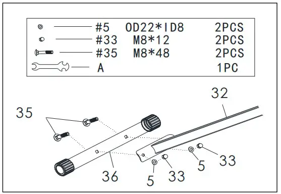
STEP 3:
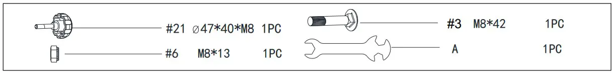
Take out the Bolt (No. 3) and Nut (No. 6) from manual bag. Insert the Connecting Tube (No. 15) into the metal bracket slot of Seat Connecting Tube (No. 31). Then insert Bolt (No. 3) into Seat Connecting Tube (No. 31) and secure Nut (No. 6) using Spanner (No. A).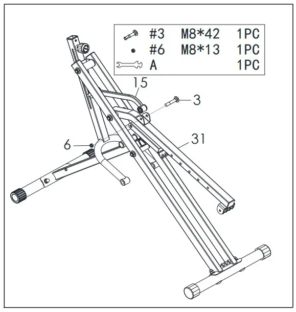
STEP 4:
Loosen and pull out the Knob (No. 10) from the Pedal Connecting Tube (No. 9), insert Handlebar Tube (No. 7) into Pedal Connecting Tube (No. 9). Then insert and secure with Knob (No. 10) after adjusting to proper height.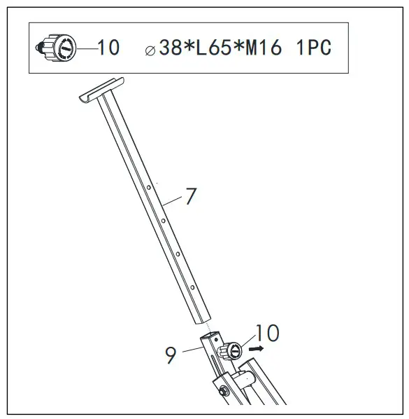
STEP 5:
Remove preassembled 2 Bolts (No. 3), 2 Washers (No.5) and 2 Nuts (No. 33) from the Handlebar (No. 4) and attach the Handlebar (No. 4) to the Handlebar Tube (No. 7) using 2 Bolts (No. 3), 2 Washers (No. 5) and 2 Nuts (No. 33) that were removed and secure with Spanner (No. A).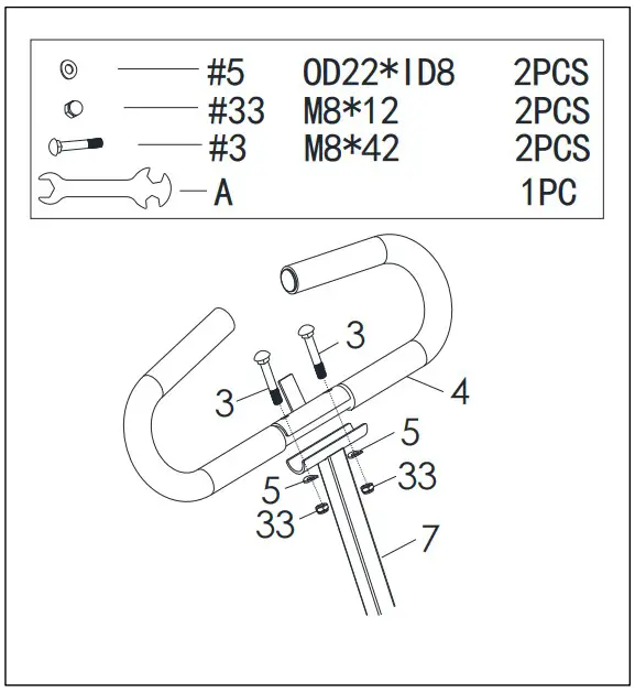
We value your experience using Sunny Health and Fitness products. For assistance with parts or troubleshooting, please contact us at [email protected] or 1-877 90SUNNY (877-907- 8669).
STEP 6:
Insert the Meter (No. 41) onto the tab on the Handlebar (No. 4).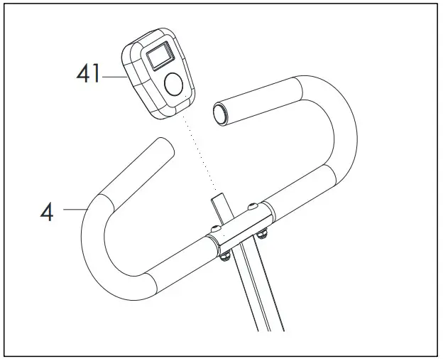
STEP 7:
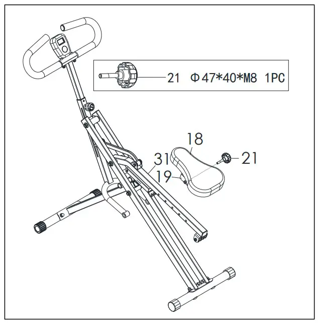
Take out the Knob (No. 21) from the manual bag.
Attach the Fixed Iron Sheet (No. 19) to the Seat Connecting Tube (No. 31), adjust the Seat (No. 18) to your desired position, then tighten and secure with the Knob (No. 21).
STEP 8:
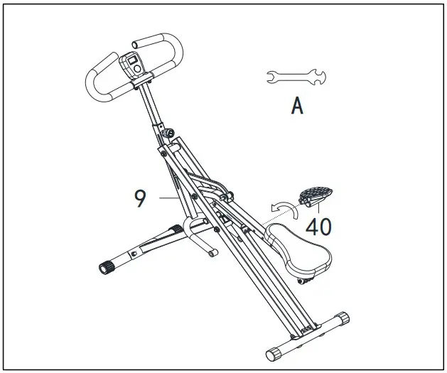
Attach the Left & Right Pedals (No. 13 & No. 40) to the Pedal Connecting Tube (No. 9) and tighten Left & Right Pedals (No. 13 & No. 40) clockwise with Spanner (No. A).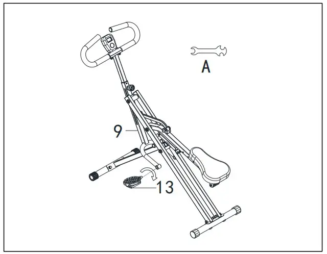
STEP 9:
Unhook Exercise Bands (No. 42) from the Seat Connecting Tube (No. 31), and connect the Exercise Bands (No. 42) to the hooks on the Main Frame (No 28).
The assembly is complete!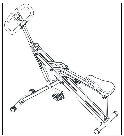
BATTERY INSTALLATION & REPLACEMENT
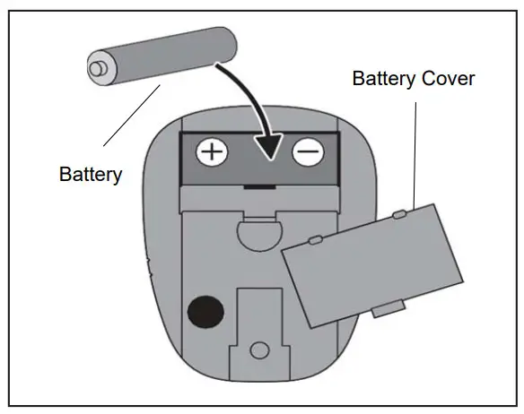
BATTERY INSTALLATION:
- Take out 1 AA battery from manual bag.
- Press the buckle of battery cover on the Meter (No. 41), then remove battery cover.
- Install 1 AA battery into the battery case on the back of the Meter (No. 41). Pay attention to the battery + and – poles before installing.
- Press the buckle of battery cover, then put the battery cover back to the back of the Meter (No. 41).
The installation is complete!
BATTERY REPLACEMENT:
- Press the buckle of battery cover on the back of the Meter (No. 41), then remove battery cover.
- Remove the 1 old AA battery in the battery case and install 1 new AA battery into the battery case on the back of the Meter (No. 41). Pay attention to the battery + and – poles before installing.
- Press the buckle of battery cover, then put the battery cover back to the back of the Meter (No. 41).
The replacement is complete!
NOTE: Dispose battery according to your state and regional guidelines
EXERCISE METER
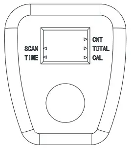
SPECIFICATIONS:
TIME: 00:00-99:59 MIN/SEC.
COUNT (CNT): 0-9999 STROKES
CALORIES (CAL): .0-9999 KCAL
TOTAL.: 0-9999 STROKES
FUNCTIONS:
TIME: Displays the workout time while exercising.
COUNT (CNT): Accumulate the strokes while exercising.
CALORIES (CAL): Displays calories amount burned while exercising.
TOTAL: Displays the total number of strokes since batteries installed.
SCAN: Automatically scan through each function between ①TIME ②CALORIES (CAL) ③TOTAL.
KEY FUNCTION:
MODE: Press to select the function you want. Hold the key for 4 seconds to reset all values.
OPERATION PROCEDURES:
AUTO ON/OFF: The meter will turn on when exercise starts or when MODE is pressed. The meter will shut off automatically after there is no activity for 4 minutes.
ADJUSTMENT INSTRUCTIONS
ADJUSTING THE HANDLEBAR
Loosen the Knob (No. 10) and pull. Raise or lower the Handlebar Tube (No. 7) to desired height. Tighten the Knob (No. 10).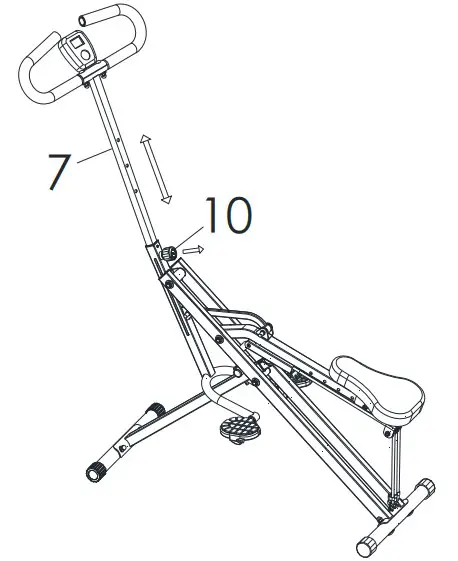
ADJUSTING THE SEAT
Loosen and remove the Knob (No. 21) located under the Seat Connecting Tube (No. 31). Move the Seat (No. 18) to desired position, then re-tighten the Knob (No. 21).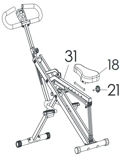
ADJUSTING THE SEAT TUBE
To adjust the Seat Tube (No. 25), lift the Seat Connecting Tube (No. 31). Remove the Pin (No. 29) from Front Connecting Tube (No. 32) and raise or lower the Seat Tube (No. 25) to desired position. Re-insert the Pin (No. 29) to secure. Then lower the Seat Connecting Tube (No. 31). Raising or lowering Seat Tube (No. 25) will change the difficulty of your exercise.
NOTE: Make sure Exercise Bands (No. 42) are not hooked to Main Frame (No. 28) when adjusting the Seat Tube (No. 25). Do not extend the Seat Tube (No. 25) to pass “MAX” line.
ADJUSTING THE EXERCISE BAND
You can adjust the difficulty of your exercise by adjusting the Exercise Bands (No. 42). To reduce difficulty, unhook Exercise Bands (No. 42) from the Main Frame (No. 28) and connect the Exercise Bands (No. 42) to the hooks on the Seat Connecting Tube (No. 31).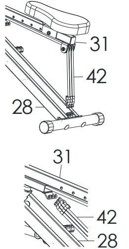
ADJUSTING THE BALANCE
In order to achieve a smooth and comfortable ride, you must ensure that the bike is stabled and secured. If you notice that the bike is unbalanced during use, you should adjust the End Caps (No. 37) located on the rear stabilizer until the bike becomes levelled with the floor surface.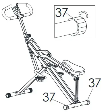
FOLDING INSTRUCTIONS
A. Adjust the Seat Tube (No. 25) to the lowest level by the Pin (No. 29).
NOTE: Make sure Exercise Bands (No. 42) are not connected to Main Frame (No. 28) when folding.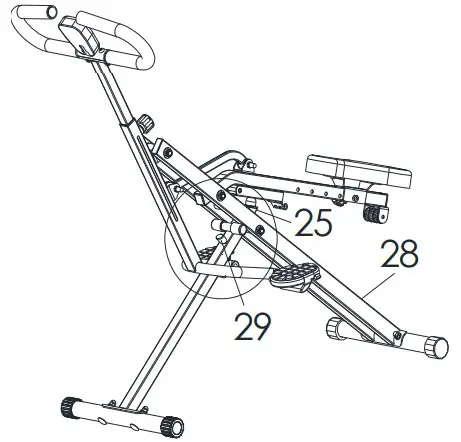
B. Adjust the Handlebar Tube (No. 7) to the lowest level by Knob (No. 10).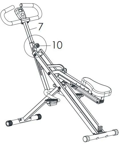
C. Hold the Handlebar (No. 4) and fold the product.